
Related Manuals for Oxford Instruments ANDOR MicroPoint 4


Summary of Contents for Oxford Instruments ANDOR MicroPoint 4
- Page 1 8.2 x 8.2 mm / 512 x 512 sensor Lowest Noise Imaging EMCCD MicroPoint 4 Version 3.1 rev 25 September 2023 User Guide For model: MP-420 © Andor Technology Ltd. 2023...
-
Page 2: Table Of Contents
SAFETY AND WARNING INFORMATION ..................6 Laser Safety Special Warnings ......................8 Section 1: Introduction ...........................13 1.1 MicroPoint 4..................................13 1.2 Help and Technical Support .............................14 1.3 Disclaimer .....................................15 1.4 Copyright and Protective Notices .........................15 1.5 Trademarks and Patent Information ........................15 1.6 Supplied Components MicroPoint 4 ........................16 1.7 Accessories .................................. - Page 3 2.3 Lasers ....................................40 2.3.1 Laser Intensity Control ................................40 2.3.2 Laser On/Off Control..................................40 Section 3: Installation..........................41 3.1 Location ....................................41 3.1.1 Ventilation ......................................41 3.2 Assembly ....................................41 3.3 PC Workstation Operating System Notes ......................41 3.4 Software ....................................41 Section 4: Operation ..........................42 4.1 Overview ....................................42 4.2 Emergency Mains Disconnection ......................... 42 4.3 Power-up Sequence ..............................
- Page 4 Section 5: Maintenance and User Service Procedures ............. 58 5.1 Cleaning and Decontamination ..........................58 5.1.1 Procedure for Cleaning Dye Cells .............................58 5.2 System Alignment ................................59 5.3 Regular Checks ................................59 On a Daily Basis: ............................59 On a Weekly Basis: ........................... 59 5.3.1 Minimum Computer Requirements ..........................59 5.3.2 Annual Electrical Safety Checks ............................59 5.4 Maintenance Packages ..............................60 5.5 Service Options .................................60...
- Page 5 Revision History Version Released Description 19/9/23 Initial release of MicroPoint 4 25/9/23 Changed cover title to MicroPoint 4 Updates to the Manual Changes are periodically made to the product, and these will be incorporated into new editions of the manual. Please check for new releases of the manual at: andor.oxinst.com/downloads. If you find an issue in this manual, please contact your customer support representative (“1.2 Help and Technical Support” on page 14) with a description of the issue. Manuals for Components There are components used in the system which have separate User Manuals. These are as follows: Nitro NL100 Laser Laser-Lock Interlock ILE Integrated Laser Engine CW laser HLE High Power Laser Engine CW laser...
-
Page 6: Safety And Warning Information
SAFETY AND WARNING INFORMATION PLEASE READ THIS INFORMATION FIRST BEFORE USING YOUR PRODUCT. CAUTION - USE OF CONTROLS OR ADJUSTMENTS OR PERFORMANCE OF PROCEDURES OTHER THAN THOSE SPECIFIED HEREIN MAY RESULT IN HAZARDOUS RADIATION EXPOSURE. If the equipment is used in a manner not specified by Andor, the protection provided by the equipment may be impaired. Do not position this product so that it is difficult to operate the mains disconnecting device. See SECTION 4.2, “Emergency Mains Disconnection”. - Page 7 Electromagnetic Compatibility: As required by IEC/EN 61326-1, we must inform you that electromagnetic emissions in excess of that required by that EMC standard for the emissions class of this product can in theory occur due to its connection to other equipment. Electromagnetic Compatibility: This product has been designed and tested to perform successfully in a normal (basic) electromagnetic environment, e.g. a typical life science test laboratory, as per the EU EMC Directive. It is not designed to operate in a harsh electromagnetic environment, e.g. close to the following equipment: EMI/RFI generators, electrostatic field generators, electromagnetic or radioactive devices, plasma sources, arc welders, x-ray instruments, intense pulsed sources, or other similar sources of high energy fields whose emissions are not within the normal range expected under the EU EMC Directive. This product is a precision scientific instrument containing fragile components. Always handle it with care. Flammable Liquids: These are used in this product, so appropriate care should be taken in its vicinity, e.g. not using any ignition sources close to the areas where these are located. Toxic substances: These are used in this product, so appropriate care should be taken as per the relevant Safety Data Sheet provided with this product. Optical Fibres: It is important that you read “Working with Optical Fibres” on page 12 Do not wet or spill liquids on the product, and do not store or place liquids on the product. If spillage occurs on the product, switch off power immediately, and wipe off with a dry, lint-free cloth. If any ingress of liquids has occurred or is suspected, unplug the mains cables and do not use. Contact customer support. See “5.1 Cleaning and Decontamination” on page 58. Do not expose the product to open flames. Do not allow objects to fall on the product. version 3.1 rev 25 SEPTEMBER 2023...
-
Page 8: Laser Safety Special Warnings
Laser Safety Special Warnings READ AND DO NOT IGNORE! CAUTION – USE OF CONTROLS OR ADJUSTMENTS OR PERFORMANCE OF PROCEDURES OTHER THAN THOSE SPECIFIED HEREIN MAY RESULT IN HAZARDOUS RADIATION EXPOSURE • This product contains lasers, so you must be aware of the hazards associated with the use of the powerful laser radiation that can be emitted by this product. • Laser radiation is emitted by this product when the Emission Indicator LEDs are illuminated on the laser source used. • It is extremely important that you read the user guides associated with each laser source used by MicroPoint, See section “Manuals for Components” on page 5. - Page 9 • The power indicated on this product would be very tame if it was a light bulb, but this should not deceive you as laser radiation is quite different. • Laser radiation differs from ordinary light primarily because its optical power can be concentrated into a narrow, low-divergence beam, whereas, for example, a standard light bulb diffuses its light in all directions and thus spreads out its power. It’s a bit like the difference between walking outside on a sunny day versus having the sun’s light concentrated on your skin using a magnifying glass. • Laser safety for this type of product is about reducing risk, rather than being able to eliminate it because access is usually required for the applications that it is typically purchased for, so it is not completely safe. • Be aware that visible laser light is dangerous as well as invisible. • Be aware that this product may emit invisible laser radiation outside the visible spectrum of 400 nm - 700 nm, which has the added danger that it cannot be seen. If you have such lasers, we advise that you purchase fluorescent cards that assist with observing the presence of the wavelength(s) of invisible laser radiation emitted by this product and that you use them safely. • In normal use, the Dye Laser converges to a focal point on the microscope stage and then diverges, but if the objective lens is not fitted, then the beam is collimated and is more hazardous. • It is important to remember to beware reflections from objects such as tools or clips placed close to the laser beam emitted from the microscope objective. • One of the primary means of protection is protective housing, which as IEC 60825-1 says, “prevents human access to [hazardous] laser radiation (including errant laser radiation)… except when human access is necessary for the performance of the function(s) of the product.”...
- Page 10 Laser Product Safety Standards • This has been designed and manufactured to comply with the international laser product safety standard IEC 60825-1 and the U.S. CDRH Regulation 21CFR § 1040.10 to reduce risk as far as is reasonably practicable. • In most instances our Customer Support Team install the system according to the same standards, but if there has been an agreement that you should install all or part of the laser product system, then you take responsibility to install this according to the same standards. Laser Safety Protection Measures The following protection measures are used in the product to reduce, but not eliminate, the risk of exposure to hazardous laser radiation in accordance with the international product laser safety standard IEC 60825-1 and U.S. CDRH Regulations 21 CFR 1040.10 and 1040.11: Emission LEDs See the relevant sections of the laser source’s user guide in “Manuals for Components” on page 5 Key Switch See the relevant sections of the laser source’s user guide in “Manuals for Components” on page 5 Protective Housing • Except at the identified laser apertures at the optical fibre output couplers, or at the ends of the attached optical fibres, or at the microscope stage, or other locations identified as a laser aperture in an attached laser product, the laser radiation within this product has been housed within an aluminium enclosure or inside an optical fibre for your safety. • Therefore, do not attempt to disassemble this product, including removing optical fibres, or try to gain access to its laser radiation, otherwise you endanger yourself and possibly others. Safety Interlocks • Safety interlocks are automatic devices, such as switches or sensors, that are used to prevent human access to laser radiation by stopping the laser product emitting (or in some instances reducing the power to a safe level, but not in this product). •...
- Page 11 Laser Safety Labelling Another important protective measure is labelling, which is described in the following sections and you must understand what these mean. Laser Aperture Locations • A laser aperture label indicates where laser radiation is emitted as a warning. • If the point where laser is emitted from your system does not have such a label then contact your occupational laser safety department and/or our Customer Support Team to arrange for a label to be affixed. • The following label is located on each of the optical fibre output couplers on the unit and on the optical fibres provided with this product by Andor. • These labels indicate that during installation laser radiation may be emitted from these locations when the optical fibres are disconnected. • In the most common uses of this product, it will be connected to a larger system that includes a microscope. In such instances, the following label will be fitted beside the microscope objective, or, in the absence of an objective, the socket where the objective is attached. Microscope Oculars Warning Although Andor fits eye-piece interlocks to ensure lasers are not emitting when light from the objective is directed away from the camera ports and towards the microscope oculars, nevertheless some microscopes can cause laser “flashes” when port switching, so we warn against viewing the oculars when this is occurring as per the label below, which is fitted on your microscope in the vicinity of your oculars: Access Panels • See the relevant sections of the laser source’s user guide. Laser Product Classification Labels with Explanatory Text • Copies of these labels can be found at the beginning of the Laser Safety Special Warnings section. • The values on these labels are intended as maximum values for classification purposes based on IEC 60825-1 Condition 3 (using a 7 mm limiting aperture to simulate the eye’s pupil at a distance of 100 mm from the laser aperture) taking into account future versions of this product and possible failure scenarios. Typical values of pulse energy are going to be less. • The values and laser class are based on the latest methodology for classifying pulse lasers in the 2014 edition of IEC 60825-1.
- Page 12 CDRH Certification Label The Controller’s rear panel label includes the words “Complies with 21 CFR 1040.10 and 1040.11 except for conformance with IEC 60825-1 Ed. 3., as described in Laser Notice No. 56, dated May 8, 2019”. This means that it complies with the U.S. Federal Regulations for laser products as overseen by the Center for Devices and Radiological Health (CDRH), which is part of the Food and Drug Administration (FDA), by means of IEC 60825-1 Edition 3 as allowed by CDRH Laser Notice No. 56, except for some additional requirements as described in that Notice. Working with Optical Fibres • This was installed by our Customer Support Team. For your safety, only they should remove or inspect optical fibres. • The laser radiation passing through fibres is potentially hazardous, so great care should be taken to avoid exposure to this radiation. • Optical fibres can be easily damaged by bending or general mishandling, and are especially prone to damage by bending close to the connector. • Ensure that the minimum bend diameter or radius is never exceeded when handled or coiled. • The bend diameter is the diameter of the circle created by coiling the fibre, and the bend radius is half of this and created by the “corners” in your fibre layout. • The FOA state that the minimum bend diameter is 40 times the outer diameter (OD) of the cable when under tension or 20 times when not under tension. • The NL100/ILE/HLE output fibres are all 3 mm OD, so the minimum bend diameter is 120 mm under tension. We recommend that you aim to have a bend diameter of 150 mm or preferably more. • The couplers are not designed to withstand pulling of the fibre. If the fibre is pulled the system performance could be compromised, the system may fail, or you may even be exposed to hazardous laser radiation. Label Symbols Laser radiation hazard. EU CE Mark by which we indicate that this product meets the requirements all the relevant EU Product Directives that require this mark, including the Low Voltage Directive for safety (as this product in manufactured in Northern Ireland, it does not require the UKCA Mark).
-
Page 13: Section 1: Introduction
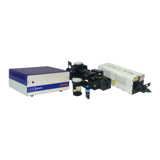
Section 1: Introduction 1.1 MicroPoint 4 Thank you for choosing the Andor MicroPoint System. This user guide contains useful information and advice to ensure optimum performance of your new system. Figure 1: MicroPoint 4 MicroPoint 4® is the 4th generation of the popular photostimulation tool from Andor. Previous generation MicroPoints have been used in hundreds of successful research studies and continue to provide a powerful and flexible tool for ablation, uncaging and, at lower powers, for bleaching and optogenetics. The new version supports a wider range of applications due to its more sophisticated control hardware, fast galvanometer drives and solid-state lasers. MicroPoint Nitro uses the classic nitrogen-pumped dye laser system, which supports up to 24 different wavelengths. Dye cells are available across the UV-Visible spectrum from 365 to 656 nm and these provide pulsed illumination up to 15 µJ with 3 - 5 ns pulse width and 20 Hz pulse rate. MicroPoint Pico introduces an ultra-compact solid-state Nd:YAG laser delivering 1ns pulses with a repetition rate of up to 5 kHz, at user selected wavelengths of 355 or 532 nm. Pulse energies up to 2 and 10 µJ respectively allow fast, progressive microsurgery, ablation, uncaging and DNA damage. When tightly integrated with fast galvos and smart control, Pico delivers leading edge performance with increased precision and productivity. Pico is available on galvanometer models only. M icroPoint 4 adds optional support for Continuous Wave (CW) lasers by means of a fibre spot adapter (FSA). CW lasers (such as those used in Andor’s ILE or HLE) are coupled to the FSA using a multimode optical fibre. CW lasers are preferred for FRAP (Fluorescence Recovery After Photobleaching), photoactivation and photoswitching. CW lasers are available for both manual and galvanometer models. MicroPoint 4 Nitro and Pico models can be combined with CW lasers. Pico and FSA are combined in a dichroic block by virtue of non-overlapping wavelengths. The laser source and wavelength can be selected through a software control protocol. While switching between Nitro and FSA requires exchange of a dye cell but takes only a few minutes to complete. MicroPoint galvanometer and manual versions have the following capabilities and user interface: •... -
Page 14: Help And Technical Support
1.2 Help and Technical Support If you have any questions regarding the use of this equipment, please contact the representative* from whom your system was purchased, or: Europe Andor Technology Ltd. Andor Technology 7 Millennium Way 300 Baker Avenue Springvale Business Park Suite # 150 Belfast Concord BT12 7AL MA 01742 Northern Ireland Tel. +44 (0) 28 9023 7126 Tel. +1 (860) 290-9211 Fax. +44 (0) 28 9031 0792 Fax. +1 (860) 290-9566 Asia-Pacific China Andor Technology (China) Andor Technology (Japan) Haitong Times Business Center, 5F IS Building Building B2 West, 3-32-42 Higashi-Shinagawa... -
Page 15: Disclaimer
1.3 Disclaimer THE INFORMATION CONTAINED HEREIN IS PROVIDED “AS IS” WITHOUT WARRANTY, CONDITION OR REPRESENTATION OF ANY KIND, EITHER EXPRESS, IMPLIED, STATUTORY OR OTHERWISE, INCLUDING BUT NOT LIMITED TO, ANY WARRANTY OF MERCHANTABILITY, NON-INFRINGEMENT OR FITNESS FOR A PARTICULAR PURPOSE. IN NO EVENT SHALL ANDOR BE LIABLE FOR ANY LOSS OR DAMAGE, WHETHER DIRECT, INDIRECT, SPECIAL, INCIDENTAL, CONSEQUENTIAL OR OTHERWISE HOWSOEVER CAUSED WHETHER ARISING IN CONTRACT, TORT OR OTHERWISE, ARISING OUT OF OR IN CONNECTION WITH THE USE OF THE INFORMATION PROVIDED HEREIN. 1.4 Copyright and Protective Notices The copyright in this document and the associated drawings are the property of Andor Technology Ltd. and all rights are reserved. This document and the associated drawings are issued on condition that they are not copied, reprinted or reproduced, nor their contents disclosed. The publication of information in this documentation does not imply freedom from any patent or proprietary right of Andor Technology Ltd. or any third party. 1.5 Trademarks and Patent Information Andor, the Andor logo, MicroPoint 4 and Fusion are trademarks of Andor Technology Ltd. Andor Technology Ltd is an Oxford Instruments company. All other marks are property of their owners. -
Page 16: Supplied Components Micropoint 4
1.6 Supplied Components MicroPoint 4 Some of the components of the MicroPoint 4 are covered in other manuals. These are the ILE and HLE laser engines (optional), and the Laser-Lock (interlock box). Please refer to these manuals online for operation and safety information. The standard components supplied with MicroPoint 4 are shown in Table 1. Table 1: Standard components supplied with MicroPoint 4. Quantity Quantity Optical Head (Nitro galvo model Fibre Optic for NL100 shown with FSA) (option) Optical Head Fibre Optic for ILE/HLE (Pico galvo model (option) with FSA) - option NL100 Trigger Cable (BNC) NL100 Laser (option) ILE or HLE Laser (option) HLE Trigger Cable (BNC) Micropoint 4 Controller NL100 Interlock Cable. LCD Touchscreen Remote Controller Interlock Cable Kit (dye cell, (manual version) mirror block etc) -
Page 17: Accessories
1.7 Accessories A range of optional accessories are available to order, please contact your local sales representative for further information. 1.7.1 Core Unit, Laser Sources and Adapters This table shows order codes for the core units - galvo and manual options. For full table see the Specification Sheet. Table 2: Core Units Part Numbers MicroPoint 4 Galvo Select Core System based on your Microscope Zeiss Axio, Leica DM, Leica DMI8, Zeiss Axiovert 200 Evident/Olympus: All Nikon models Evident/Olympus IX/BX BX51/WI model MicroPoint 4 Galvo with... -
Page 18: Laser Dyes
1.7.2 Laser Dyes This table shows part numbers and key specifications for the different laser dyes available. Table 3: Laser Dye Part Numbers MicroPoint Laser Dyes Dye Part Number Centre (±1) Wavelength/nm Efficiency (Relative to 435nm)/% MP-27-365-DYE MP-27-388-DYE MP-27-390-DYE MP-27-404-DYE MP-27-419-DYE MP-27-422-DYE MP-27-435-DYE MP-27-471-DYE MP-27-481-DYE MP-27-514-DYE MP-27-521-DYE MP-27-539-DYE MP-27-543-DYE MP-27-551-DYE MP-27-576-DYE MP-27-582-DYE MP-27-590-DYE MP-27-593-DYE MP-27-613-DYE MP-27-622-DYE... -
Page 19: Micropoint Laser And Microscope Interlock Components
1.7.3 MicroPoint Laser and Microscope Interlock Components MicroPoint lasers are all supplied with interlock systems to ensure safety of the user and to meet standards such as CDRH and IEC-60825. We list the parts and assemblies currently supported to ensure installation is compliant across the many microscope models and configurations. If you have an instrument that is not listed here, we will be required to create a new configuration. It is essential that you do not disable or otherwise interfere with the proper operation of the interlock system. The resulting hazards can be severe and lead to serious damage to eyes and body parts that come into contact with the intense laser beams used in these products. The Food and Drug Administration’s (FDA) Center for Devices and Radiological Health (CDRH) regulate the manufacture of radiation emitting electronic products. Andor products, including all MicroPoint 4 models comply with FDA regulations contained in Title 21 Code of Federal Regulations Parts 1000-1299 (21 CFR 1000- 1299). According to section 531 of the FD&C Act. The requirements specific to laser products are referred to as the Federal Laser Product Performance Standard or “FLPPS”. The International Electrotechnical Commission (IEC) Standards headquartered in Geneva, Switzerland, is the organization that prepares and publishes international Standards for all electrical, electronic and related technologies including laser products. Andor MicroPoint products are complaint with IEC 60825-1:2014 regulations. The following table describes the part codes, microscopes and primary function of the interlock components. Note: when more than one laser source is used in an instrument, an interlock combiner is required. Table 4: Interlock Components. - Page 20 IL-MEBS Mosaic Epi-port Beam Splitter Interlock IL-MIDU Mosaic Infinity Dual-Laser Interlock Ext IL-MINF Mosaic Infinity Interlock Cable IL-MMAR Mosaic Argon Laser Interlock Replacement IL-MMBD Mosaic Body Interlock Replacement Kit Mosaic Duet Body Interlock Replacement IL-MMDU IL-MMLD Mosaic Laser Diode Interlock Replacement IL-MOS-DUET-UPG Historic Mosaic 3 Interlock Upgrade Kit IL-MOS-UPG Historic Mosaic 3 Interlock Upgrade Kit IL-MPNC MicroPoint Non-CE Interlock MODULAR MicroPoint NL-100 Interlock Replacement IL-MPNL IL-NC2+ Nikon C2+ Interlock Adaptor IL-NCA1 Nikon A1* Confocal Interlock Adapt (Part O) IL-NFN1 Nikon FN1 LV-TI3 Interlock Kit...
-
Page 21: Cw Laser Sources For Micropoint 4 Fibre Spot Adapter
1.7.4 CW Laser Sources for MicroPoint 4 Fibre Spot Adapter The fibre spot adapter provides an optical fibre input for continuous wave (CW) lasers, delivering a focused spot to the specimen plane. In combination with the new smart controller, the FSA extends MicroPoint 4 capabilities for scanned multi-region FRAP, photoconversion and photoactivation. When your specimen requires sustained absorption or more gentle treatment than the energetic pulsed lasers, CW lasers can provide the right tool for the job. You can use Andor’s integrated laser engines, ILE and HLE (Figure 2), or supply your own laser source: subject to optical compatibility and safety requirements. The FSA is supplied with a multi-mode optical fibre for ILE and µ HLE. For other lasers, a 25 or 50 m multimode fibre is available. For more information see the MicroPoint 4 or ILE/HLE specification sheets or ask your local Andor representative. Figure 2: Andor's Integrated Laser Engine (ILE) (Left) and High-Power Laser Engine (HLE) (Right) with optional millisecond switching to multi-port outputs. -
Page 22: Epifluorescence And Optogenetic Light Sources For Micropoint
1.7.5 Epifluorescence and Optogenetic Light Sources for MicroPoint When required, Andor supplies LED epi-fluorescence light sources as part of the sub-system. Andor works with CoolLED to qualify and supply suitable LED models. pE-300 and pE-800 (Figure 3) are the primary sources. These devices are controlled via USB serial communications and TTL for triggered operation. LEDs are efficient and long lasting (20,000 hr) and are excellent low noise optical sources for fluorescence imaging and optogenetic stimulation, where required power densities for stimulation are low. We recommend liquid light guide (LLG) coupling to minimise any vibration-coupling, or they can be directly coupled to microscope flanges. The table shows the key characteristics of the two models. For more information refer to the CoolLED user manuals or contact your Andor representative. Figure 3: CoolLED LED sources for fluorescence microscopy supplied by Andor. a) pE300 3-line LED with LLG coupling. b) pE800 8-line LED source with LLG coupling. Table 6: Key features of pE300 and pE800 LED light sources for epi-fluorescence and optogenetics applications. -
Page 23: Beam Splitter Cubes For Combining Photostimulation And Epifluorescence Light Sources
1.7.6 Beam Splitter Cubes for Combining Photostimulation and Epifluorescence Light Sources In most microscope systems using MicroPoint there will be multiple illumination sources which allow the user to observe the specimen as well as apply targeted photostimulation from MicroPoint. The epifluorescence light source will be coupled to the MicroPoint with a flange and sometimes via a liquid light guide (LLG). To combine the illumination beams in the MicroPoint we use custom beam splitter plugs (BSP). A beam splitter plug (BSP) splits or combines the incident beam(s) into 2 components – the transmitted beam (T) and the reflected beam (R) at 90 degrees. Different beam splitter plugs are available with different percentages of T and R, and with different wavelengths for the transmitted and reflected light. See Table 7. A block diagram highlighting the beam splitter plug (BSP) is shown in Figure 4. The BSPs are large, easy to handle and exchange if needed, with an integrated laser safety interlock which stops the MicroPoint laser from firing when no BSP is in the BS block to prevent unnecessary access to hazardous laser radiation as required by IEC 60825-1. Figure 4: a) Block diagram of the MicroPoint showing Beam Splitter Plug (BSP) which allow beam combination for Epi and Photostimulation sources. - Page 24 Figure 5: MicroPoint coupled to Mosaic AND Epi fluorescence sources. Mosaic is a patented DMD based device for patterned illumination, supporting lasers and LEDs for FRAP, photo-conversion, activation and optogenetics applications. Highlighted in orange are the BSPs and where they provide beam-combining duties to deliver extremely flexible solutions for complex experimentation. Table 7: Beam Splitter options available for MicroPoint and Mosaic.
-
Page 25: Microscope And Micropoint Flanges
1.7.7 Microscope and MicroPoint Flanges Figure 4 and Figure 5 show MicroPoint coupled to the microscope via a flange. When using the original microscope Epi port, the flanges must match the original manufacturer and model. But if using Andor FFEP (flat field epi port - Section 1.9), the Andor internal standard specifies Zeiss 38 mm flanges. The table defines the flanges available for coupling to Leica, Nikon, Evident Olympus and Zeiss microscope epi ports. Note that if the user wishes to re-use the epifluorescence light source, which also has a flange, then a female flange must be provided on the MicroPoint lamphouse block to allow connection. Be sure to match male and female flanges when ordering. Figure 6: a) Zeiss and b) Nikon Microscope Flanges Table 8: Flanges to support MicroPoint coupling to microscope epi ports and lamp houses. MicroPoint uses Zeiss 38 mm flanges as its internal coupling standard. Part Number Description Part Number... -
Page 26: Microscope Optical Coupling With Andor Flat Field Epi Ports (Ffep)
1.7.8 Microscope Optical Coupling with Andor Flat Field Epi Ports (FFEP) We use the Andor FFEPs when building around new microscopes to ensure best compatibility. When retrofitting to existing systems we review instrument configuration and re-use the microscopes existing equipment. However when MicroPoint is supplied with Mosaic 3, we must use Andor FFEP to optimise performance. FFEPs are designed for individual microscopes as shown in the table. Note that FFEP models are used with Mosaic 3 small format models, while FFEP-I models are used with Mosaic large format. MicroPoint can be adapted to either FFEP or FFEP-I. Figure 7 shows examples of FFEP-I (with iris) for Zeiss and Olympus microscopes, the table shows the adapters available for many microscope models. Figure 7: Examples of flat field epi ports (FFEP) and FFEP-I for Zeiss and Olympus inverted microscopes. Products are available for all the scopes listed in the table below. Of special note: Leica DM6B and DM6-FS microscopes use diffusers in the epi-fluorescence axis to improve uniformity. These are not compatible with MicroPoint 4. The diffuser must therefore be removed from the axis by a service engineer. In some more recent developments, both Leica and Nikon has changed their epi-fluorescence axis couplings and we prefer to replace the manufacturer model with our own FFEPs... -
Page 27: Filter Cubes Combining Photostimulation With Microscope Systems
MM-7310-TE2K-FFEP FFEP TE2000 Flat Field Epi Port TE2000 MM-7310-TE2K-FFEP-I FFEP TE2000 Flat Field Epi Port TE2000 MM-7310-TI-FFEP FFEP Nikon Ti Flat Field Epi Port Nikon Ti/Ti2 MM-7310-TI-FFEP-I FFEP Nikon Ti Flat Field Epi Port Nikon Ti with Iris MM-7310-ZSAV-LENS FFEP Axiovert200 Flat Field Epi Port Axiovert 200 MM-7310-ZSAX-FFEP Mosaic EPI Axioskop Mosaic Epi Port for Zeiss Axioskop 1.7.9 Filter Cubes Combining Photostimulation with Microscope Systems The filter cubes are presented in the table overleaf. They are used to combine the Epi and Photostimulation... - Page 28 Filter Cubes Generic Part Number Notes (nm) Code Description TR-FC-XX-YY-375DC 375 LP XX-YY Substitute with Scope Specific TR-FC-XX-YY-400-532R R 400-450, R 532 LC-24 Leica DM/DMI Laser TIRF/PS Cube TR-FC-XX-YY-408DC R 350-408 LC-51 Leica DMi8 Laser TIRF/PS Cube TR-FC-XX-YY-460DC R 400-450 NK-32 Nikon Ti/Ti2 Laser TIRF/PS TR-FC-XX-YY-488DC 480 LP OL-41...
-
Page 29: Section 2: Product Overview
Section 2: Product Overview 2.1 Hardware Description This section provides an overview of the general principles of operation and a description of the hardware of MicroPoint 4. Figure 9: a) MicroPoint 4 Galvo Nitro components and b) MicroPoint 4 Manual Nitro components MicroPoint 4 Nitro uses a pulsed UV nitrogen laser to pump fluorescent laser dyes loaded into a small optical resonator cell of size 5 mm x 5 mm x 5 mm to produce pulsed beams at different wavelengths. The laser dye sets the wavelength and the resonator produces energetic laser pulses with an average power of 0.3 mW in intensity and peak of around 7 kW with a duration of 3 - 5 ns. MicroPoint 4 Pico exploits an Nd:YAG laser with 2X and 3X frequency multiplication to deliver pulses at either 355 or 532 nm (user selectable). Average power is 4 and 20 mW respectively with a peak power of 2 and 10 kW, pulse duration of ~1 ns, and repetition rate of up to 5 kHz. There is also the facility to use the Andor ILE Class 3B laser with a power range 50 - 150 mW, or the new higher-powered HLE Class 4 laser, power range 400 - 2500 mW. These are CW lasers and connect through an optional fibre spot adaptor (FSA) instead of the dye cell. The FSA can be attached to both manual and galvo models in MicroPoint 4. The laser spot can be steered or scanned using optional X-Y galvo beam optics. Power is controlled using a motorised attenuator in the MicroPoint optical head. MicroPoint 4 Galvo models are pc-controlled while the MicroPoint 4 Manual models are operated via an LCD touch screen. -
Page 30: Intended Use
2.1.1 Intended Use The MicroPoint 4 can be used in life sciences for ablation, uncaging, DNA damage and fluorophore photobleaching, photoactivation and Fluorescence Recovery After Photobleaching (FRAP). MicroPoint 4 can also be used for materials processing, for example, marking semiconductor wafers. Using the HLE or ILE, the laser source can be shared for fluorescence imaging applications and photostimulation by providing a second fibre output from the laser engine. In these cases continuous wave illumination is delivered via the FSA, which may be preferred for bleaching and optogenetics, where lower peak power is preferred. When coupled to the new fast galvos of MicroPoint 4, Pico provides a high speed tool for ablation, microsurgery, uncaging and DNA damage applications. 2.1.2 NL100 Laser Rear Panel First if we look at the back of the Nitro NL100 laser, the key goes into the slot in the bottom left hand corner. The pulse rate can be set by turning the RATE knob at the top left. Three electrical cables connect from the panel. Figure 10: NL100 laser rear panel Figure 11: Three electrical cables connect from the panel. 1 is the Interlock connector, 2 is the DC In connector which is 24 V 2A, 3 is a BNC connector for Laser Trigger In. -
Page 31: Electrical Connections, Optical Connections And Interlocks
2.2 Electrical Connections, Optical Connections and Interlocks 2.2.1 Electrical Connections For connection positions on the back of the controller box see “2.2.5 Back Panel on MicroPoint 4 Controller” on page 39. Only galvo models are PC-controlled. These may be either NL100 Nitro laser or ILE/HLE versions. 2.2.1.1 Nitrogen Laser NL100 Configuration, PC-Controlled, Galvo Version The back panel of the MicroPoint 4 controller is shown with the relevant connections. NL100 Laser 24V DC Trigger 24V DC PS-29 Piezo Foot Switch (optional) (optional) MicroPoint 4 Optical Head Computer with FSA and galvos Figure 12: Electrical Connections NL100 PC Galvo version see “Back Panel on MicroPoint 4 Controller” on page 39 version 3.1 rev 25 SEPTEMBER 2023... -
Page 32: Ile/Hle Laser Configuration, Pc-Controlled, Galvo Version
2.2.1.2 ILE/HLE Laser Configuration, PC-Controlled, Galvo Version The schematic shows the back panel of the MicroPoint 4 controller with the relevant connections. 24V DC Piezo Foot Switch (optional) (optional) MicroPoint 4 Optical Head Computer with FSA and galvos Figure 13: Electrical Connections ILE/HLE PC Galvo version see “Back Panel on MicroPoint 4 Controller” on page 39 version 3.1 rev 25 SEPTEMBER 2023... -
Page 33: Pico Laser Galvo Version
2.2.1.3 Pico Laser Galvo Version 24V DC Piezo Foot PS-29 Controller Switch (optional) (option) Computer MicroPoint 4 Optical Head and Pico Laser with FSA and galvos Figure 14: Electrical Connections Pico Galvo Version see “Back Panel on MicroPoint 4 Controller” on page 39 version 3.1 rev 25 SEPTEMBER 2023... -
Page 34: Nitro Laser Manual Version
2.2.1.4 Nitro Laser Manual Version NL100 Laser 24V DC Trigger 24V DC PS-29 Foot Switch Manual Controller MicroPoint 4 Optical Head with Dye Cell Figure 15: Electrical Connections Nitro Laser Manual Version see “Back Panel on MicroPoint 4 Controller” on page 39 version 3.1 rev 25 SEPTEMBER 2023... -
Page 35: Ile/Hle Laser Manual Version
2.2.1.5 ILE/HLE Laser Manual Version ILE/HLE Laser 24V DC PS-29 Foot Switch Manual Controller MicroPoint 4 Optical Head with Dye Cell Figure 16: Electrical Connections ILE/HLE Manual version see “Back Panel on MicroPoint 4 Controller” on page 39 version 3.1 rev 25 SEPTEMBER 2023... -
Page 36: Optical Connections
2.2.2 Optical Connections The NL100 laser is connected to the optical head by a 200 µm fibre optic cable for all Nitro models. The ILE/ HLE laser is connected to the optical head by a 25 or 50 µm fibre optic cable. The Pico laser is integrated into the optical head so there is no fibre optic cable needed. Pico Laser Figure 17: Optical Connections version 3.1 rev 25 SEPTEMBER 2023... -
Page 37: Interlock Connections
2.2.3 Interlock Connections A BNC connector is provided on the MicroPoint 4 controller so that the user can interlock the lasers using external switches. When the interlock contacts are open, TTL signals are prevented from being sent to all lasers and the pico laser is disabled. If the system is sold with the HLE Class 4 laser lock, there are two types of interlock inputs: 1. standard interlock for the microscope components and 2. a remote interlock, typically for the lab door. After a trigger event 1. When the microscope interlock is opened, the user must close the interlock and the laser configuration will be re-established. 2. When the remote interlock is opened, the user must close the interlock and then push the button on the Laser-Lock. MicroPoint 4 Dye Laser Optical Head and FSA MicroPoint 4 Controller... -
Page 38: Ttl Outputs From Micropoint 4 Controller To Ile/Hle
2.2.4 TTL Outputs from MicroPoint 4 Controller to ILE/HLE Note the HLE uses the same HD15 as the ILE and the cables are common. Table 11: TTL Outputs for the ILE and HLE Function Function Function NC (No Connection) TTL Out 4 Dual output switch Ground Ground TTL Out 1 Ground TTL Out 2 Ground TTL Out 3 Ground Function Function Function TTL Out 7 TTL In 4 Dual output switch Ground Ground TTL Out 1 Ground TTL Out 5 TTL Out2 Ground TTL Out 6 TTL Out 3... -
Page 39: Back Panel On Micropoint 4 Controller
2.2.5 Back Panel on MicroPoint 4 Controller This is a photograph of the back panel of the MicroPoint 4 controller. Figure 19: Connection Panel on MicroPoint 4 Controller Power Input For connection to the external power supply unit (PSU) (refer to “MicroPoint 4 Controller Electrical Power Specifications” on page 65). An On/Off switch is also present (shown above). A USB 3 compatible cable is connected between the USB socket and a PC. We strongly recommend you use the locking device built into the cable. Table 12: Connections on the back of the Controller Label Input/Output/ Connection Function Communication Galvo XY Out Output Hardwired to galvos Laser beam steering Communication ILE/HLE TTL Output ILE/HLE Input if used... -
Page 40: Front Panel On Micropoint 4 Controller
2.2.6 Front Panel on MicroPoint 4 Controller Figure 20: Front of Controller The light on the front panel indicates the system status. Yellow When initialising - for 6 seconds Green Flashing It continues initialising - for 11 seconds Solid Green When the Controller is ready During the green flashing phase you can send commands via the touchscreen but not fire the laser. After the initial boot up: Green System is idle and ready to receive commands Yellow Armed and awaiting fire command Laser is currently firing 2.3 Lasers Refer to laser safety section in the front of the manual for more information. 2.3.1 Laser Intensity Control The intensity of the laser is controlled manually using the manual slider and motorised attenuator - see section 4.15. It can also be set on the manual LCD controller - see “4.16 Laser Intensity Control” on page 52 - for manually controlled machines or through Fusion for PC-controlled systems. 2.3.2 Laser On/Off Control See Section “4.3 Power-up Sequence” on page 42 for the power up sequence and “4.4 Power-down Sequence” on page 42 version 3.1 rev 25 SEPTEMBER 2023... -
Page 41: Section 3: Installation
Section 3: Installation WARNING: THE MICROPOINT SYSTEM MUST BE INSTALLED BY AN AUTHORIZED INSTALLATION ENGINEER ACCORDING TO THE INFORMATION PROVIDED BY ANDOR. 3.1 Location Please consider a suitable space to install the MicroPoint system in your laboratory or facility prior to Andor Installation. The microscope make and model must be qualified by Andor personnel to ensure compatibility. -
Page 42: Section 4: Operation
Section 4: Operation WARNING: IF THE EQUIPMENT IS USED IN A MANNER NOT SPECIFIED BY ANDOR OR ITS DISTRIBUTORS, THE PROTECTION PROVIDED BY THE EQUIPMENT MAY BE IMPAIRED. PLEASE READ THE USER GUIDES SUPPLIED WITH YOUR SYSTEM COMPONENTS AND SOFTWARE PRIOR TO USE 4.1 Overview The MicroPoint optical head is a rigid unit that is designed using a heavy exterior that is bolted down. -
Page 43: The Dye Cell
4.5 The Dye Cell The MicroPoint supports the classic dye laser, whose wavelength is determined by the laser dye held in a cylindrical, removable dye cell (Figure 21). While in use, the dye cell is housed in the resonator block as shown in Figure 21 b. Figure 21: a) The Dye Cell and b) Thumb Screw A wide variety of dyes ranging from UV to visible can be used to obtain the desired wavelength. A table of available dyes is presented in the section “1.7.2 Laser Dyes” on page 18. Three kinds of dye cells are available depending on the wavelength selected. Popular choices for dye cell wavelengths are 365 nm and 435 nm. To increase efficiency for these wavelengths, dye cells with custom optics must be used. If the 365 nm dye is employed, a dye cell with a green dot on the lid must be used; if the 435 nm dye is employed, a dye cell with a blue dot on the lid must be used. If any of the other dyes are employed a dye cell with a yellow dot on the lid must be used. 365 nm Green Dot 435 nm Blue Dot Other wavelengths Yellow Dot CAUTION: THE TOXICOLOGICAL PROPERTIES OF THE LASER DYE ARE DESCRIBED IN THE MSDS SHEET PROVIDED WITH THE DYE. -
Page 44: To Remove And Install The Dye Cell
4.6 To Remove and Install the Dye Cell Loosen the stainless steel thumb screw located on the side of the resonator block. (Figure 23). The thumb screw is highlighted yellow in Figure 21 b and is located on the opposite side of the block from the optical fibre input. Remove the dye cell from the resonator block by gripping the cap and lifting it upwards (Figure 22). Note: Removing the dye cell will make the system inoperable. A safety Interlock ceases all emission from the laser until the dye cell is properly reinstalled. Figure 22: Removing/Replacing the Dye Cell Fibre Spot Adapter (FSA): If the system has a Fibre Spot Adapter (FSA) (Figure 23) on the optical head, to allow use with a CW laser such as Andor Integrated Laser Engine, then a blank cell is provided. The blank cell must be inserted to enable operation with the CW laser. It has an aperture where the dye cell active volume would normally be present. In other respects, it is mechanically identical to the standard dye cell and will allow the safety interlock to operate normally once installed. Figure 23: Fibre Spot Adapter FSA T o reinstall the dye cell: insert the dye cell into the resonator block by orienting the cell so that it drops freely into the bore. Do not force the cell in the resonator block. Note that the flat side of the dye cell bottom will face the fibre input when in the correct orientation. When the cell is properly installed, the bottom of the cell should be flush with the bottom of the resonator block. When the cell is in place, gently tighten the stainless-steel thumb screw located on the side of the resonator block. If you change the dye wavelength or switch to using the FSA, the focus of the instrument will probably change. To adjust the focus refer to “4.15 Focusing the MicroPoint” on page 51. -
Page 45: Replacing The Laser Dye
4.8 Replacing the Laser Dye CAUTION: THE TOXICOLOGICAL PROPERTIES OF THE LASER DYE ARE DESCRIBED IN THE MSDS SHEET PROVIDED WITH THE DYE. REFER TO THAT DOCUMENT FOR SPECIFIC INFORMATION ABOUT POTENTIAL HAZARDS. CAUTION: THE LASER DYE IS DISSOLVED IN A HIGHLY-FLAMMABLE SOLVENT, SO AVOID OPEN FLAMES AND SPARKS IN THE LABORATORY. -
Page 46: Selecting A Lamp House Port And Beamsplitter Plug
4.10 Selecting a Lamp House Port and Beamsplitter Plug WARNING: LAMPS SHOULD NOT BE REMOVED FROM THE MICROPOINT UNIT, THIS IS A SERVICE PERSONNEL ONLY OPERATION You can select the left or right lamp house port by rotating the beam splitter selection knob so that one mark points to the microscope and the other points to the desired lamp house port. Magnets and kinematic mounting on the beam splitter plug align and lock the unit in position. 4.11 Inserting the Magnetic Beam Splitter If an external lamp/LED for epifluorescence is used, a variety of magnetic beam splitters are included to either combine the MicroPoint photostimulation light path with the epifluorescence path for specimen observation, or choose between them for maximum efficiency. More information on the beamsplitters we have available is in Section 1 Table 7 on page 24 . These fit from above into the circular aperture of the lamphouse block as shown in Figure 24. If there is no need to combine epifluorescence with the dye laser, then a blank beam splitter body is included, with no optical component installed. It will still carry the safety interlock, so must be installed for MicroPoint operation. Figure 24: Beam Splitter in Lamphouse Block WARNING: BEFORE CHANGING A BEAM SPLITTER, VERIFY THAT THE LASER IS TURNED OFF. -
Page 47: Inserting Excitation Filters
4.13 Inserting Excitation Filters WARNING: THE SYSTEM SHOULD NOT BE OPERATED WITHOUT A FILTER HOLDER IN POSITION. WARNING: THE LAMPHOUSE FILTER SHOULD NOT BE REMOVED WHILE THE MICROPOINT IS IN OPERATION. WARNING: BEFORE CHANGING THE LAMPHOUSE FILTER, VERIFY THAT THE LASER AND LAMP ARE TURNED OFF. WARNING: DO NOT INSERT ANY OBJECTS INTO THE FILTER’S APERTURE EVEN IF THE SYSTEM IS NOT ENGAGED OR POWERED ON. -
Page 48: Laser Centration With Target
4.14 Laser Centration with Target Laser centration is somewhat wavelength dependent so should be checked when changing laser source, especially when switching between CW and pulsed lasers. MicroPoint has two mechanisms for beam steering: the first is used to centre the beam at the input of the focusing optics; the second is used to set the position of the laser beam in the specimen plane. The first mechanism is common to both manual and galvo models and involves a manual beam displacer, located immediately after the dye cell resonator block, as shown in Figure 26 a and b. This should be set first and does not require the laser to be emitting. Figure 26: Laser beam centred at the back focal plane target a) inverted scope b) upright scope with mirror slide A hex key is used to rotate (X) and tilt (Y) the element to centre the beam as it enters the focusing optics – see Figure 27. Note that the steering optic is factory aligned, so should only require only small changes. It is set as follows. 1. Centration of the first adjuster - manual and galvo models Install the fluorescence target in the objective turret (Figure 25). - Page 49 2. Centration of the second adjuster in manual MicroPoint models To centre the beam in the objective back focal plane, the second steering optics is first set to the factory default position as described in point 1. above for the first axis - see Figure 27. Once the beam is roughly centred in the back focal plane of the objective – make sure to use the fluorescent target (Figure 26) – you will see the laser profile similar to that shown in Figure 29. The primary beam spot is circular (see Figure 29) and needs to be centred on the target. Figure 28: Second beamsteering in manual model 3. Centration of the laser beam in MicroPoint 4 galvo models Figure 29: Dye Laser Beam Profile and Steering Moves version 3.1 rev 25 SEPTEMBER 2023...
- Page 50 4. MicroPoint 4 galvo models have independent X and Y steering, managed by the smart controller. When the controller is powered and connected to the control software, the default galvo positions are set to the centre of their range, which corresponds to the centre of the field of view. Assuming step 1 above is complete, the default galvo positions should allow the beam to be near the target centre. Fine adjustment of the spot in the specimen plane. Select the desired objective and install or select it on the microscope turret. Using the focus procedure in Section “4.15 Focusing the MicroPoint” on page 51, adjust the laser until you can cut small holes in the mirror slide. Using either the ocular target with laser safe filter cube, or the imaging system camera, you can now make final adjustments. For manual models, adjust the second beam steering component by rotation and tilt until you are satisfied with the beam position. Once centred the specimen can be moved with a fine stage to place the desired target at the stimulation point. For galvo models, to adjust beam centration, use the software to select the ‘Centre Galvos’ option on the UI (user interface). Then loosen the galvo locking screws, circled in red in Figure 30, and make small rotational adjustments of the X and Y galvo bodies until the cutting is centred in the field of view. Lock the screws finger tight, but not aggressively.
-
Page 51: Focusing The Micropoint
4.15 Focusing the MicroPoint The MicroPoint has its own focus mechanism to ensure that it remains parfocal with the microscope oculars and/or imaging ports. When the MicroPoint is installed by Andor and used with a single dye cell, it will be focused for use with your preferred photostimulation objective lens, so you should not need to adjust focus by very much unless the objective, specimen type or mounting medium has changed. If you do need to make small adjustments, the focusing ring is located on the MicroPoint body as shown in orange in Figure 32. Clockwise (CW) rotation will bring the plane of focus closer to the objective lens, while counter-clockwise rotation (CCW) will bring focus closer to the specimen. Figure 32: Adjusting the focus on the Optical Head Wavelength Specific Laser Adjustment: If you change the dye cell wavelength, or switch Pico between 355 and 532 nm you will need to refocus the system. To adjust the MicroPoint focus it is a good idea to use the chromium plated glass slide that is supplied with your instrument. Observe the slide in transmitted light and focus in the oculars or on the system camera. The slide has some scratches on the surface on which you can focus precisely. Once focused, switch the selected laser to continuous trigger mode and observe the glass slide. For the NL100 see Figure 33 - the internal trigger setting is highlighted in the top left corner in red. Provided there is sufficient laser intensity (start at 60% - see Section 4.15) and the focus is close, you will see a spot appear each time the laser delivers a pulse. While the laser is pulsing, you should move the XY stage slowly and smoothly to present a fresh area for the laser to pulse. Figure 33: Set Trigger Rate - top left version 3.1 rev 25 SEPTEMBER 2023... -
Page 52: Laser Intensity Control
To optimise focus, adjust CW and CCW in small amounts (~10 degrees) to discover in which direction the spot size gets larger. Make fine adjustments to optimise and then reduce the intensity to 40% and continue to optimise focus and intensity until you find the lowest intensity at which clear sharp spots appear for each pulse. It is a good idea to mark the focus ring with something like nail varnish, coloured lab tape, or a paint pen and colour code the marks. This will simplify future adjustments. CW Laser Adjustment with FSA: If you use a continuous wave (CW) laser such as the Andor ILE with the Fibre Spot Adapter and change source wavelength, you will need to adjust focus. Unlike the dye laser above, the FSA requires use of a fluorescent slide, e.g. kidney or highlighter pen, so that the laser bleaches fluorescence in the specimen. You can adjust focus in one of two ways with the MicroPoint 4. a Mechanical focus. Adjust focus by starting at a relatively high intensity and incrementally minimising the spot size and the intensity until you reach a small tight spot (~20 Nyquist pixels is common). b NEW Piezo offset feature of the MicroPoint 4 controller. This feature is available for USB controlled models only. If you have a piezo stage insert or piezo objective with analogue (0-10 V) control, then you can use the piezo offset to adjust the axial position of the objective or specimen when the photostimulation (PS) laser is triggered. The MicroPoint 4 will return the piezo to the imaging stage/ objective position after the PS event is complete. If you record a piezo offset value per PS wavelength, then MicroPoint 4 will automatically apply the offset for each triggered PS event. To rewire your piezo, take the 0 - 10 V BNC cable which is plugged into the piezo controller and move it to the MicroPoint 4 ‘piezo in’ connection. Then connect a BNC from MicroPoint 4 ‘piezo out’ to the piezo controller 0 - 10 V analogue input. The user interface in Andor iQ will support setting the piezo offset for all wavelengths specified by the user. The default offset is zero, but it can be set in the range ±2048 counts or ±2 Volts. One count corresponds to 0.5 mV and the range is ±20% of the piezo range. 4.16 Laser Intensity Control The MicroPoint has two methods of intensity control: •... -
Page 53: Pulse Frequency And Number
The CW laser systems use mainly solid state lasers and these can be electronically set over a range of 2 - 100% intensity with 1% resolution. This control is linear, so in the example above you would set the laser intensity to 50%. Once again this can be combined with the motorised attenuator to provide fine control over the delivered laser intensity. 4.17 Pulse Frequency and Number Both motorised and manual MicroPoint models can control pulse frequency and number. Pulse frequency determines the number of pulses delivered per second, while pulse number determines the number of pulses delivered per trigger event, or for motorised scanning, for each point in the scanned pattern. These are useful controls because experience shows that delivering energy to the specimen in several lower energy pulses, may be more effective and controllable than a single higher energy pulse. In addition, the frequency of pulse delivery will also influence the response to, or recovery from, the stimulation. See Figure 35 for the software interface settings. Figure 35: Galvo model GUI in Andor iQ software The NL-100 pulsed laser has a maximum frequency of 20 Hz (pulses per second) and has a maximum number of 80 pulses per trigger event. This is set through either the LCD panel for the manual models or the software interface for USB models. Continuous wave (CW) ILE lasers, when available, can deliver pulses with frequency 1 - 1000 Hz, a user-defined pulse width of 1 - 60,000 ms and a pulse number of 1 - 80 per trigger event or scanned point. In that case select the CW Mode checkbox below Pulse Width on the device UI shown in Figure For galvo models, there is an additional parameter: Fill Factor. This determines the density of photostimulation laser spots in a scanned pattern. Higher numbers result in lower density scanning. This is useful when the user wants to stimulate a region of interest quickly and overlap of spots within the pattern can be traded against speed of action. version 3.1 rev 25 SEPTEMBER 2023... -
Page 54: Using The Micropoint 4 Piezo Offset Feature
4.18 Using the MicroPoint 4 Piezo Offset Feature If you have an analog piezo stage or objective drive, you can make use of this feature to momentarily change the specimen Z position during photostimulation (PS). The stage is reset to the original (imaging) Z position after the PS action. This feature allows the user to correct for axial chromatic aberration in the optical train from MicroPoint 4 to the microscope objective. Chromatic aberration results in different focal planes at different wavelengths. Piezo offset allows you to set an offset value for each of the wavelengths you want to use and once set it will be automatically applied during PS. This is particularly useful if you use both UV and visible lasers in your PS work. Carry out the following steps. First, with power off, connect the analog output from your 0 - 10 V DAC (Andor USB-BoB for example) to the Piezo In BNC on the back of the Micropoint 4 controller. Then connect the Piezo Out BNC on the MicroPoint4 controller to the 0 - 10 V input of your piezo stage controller. Power up your system, start the imaging software and confirm that you have normal control of the piezo focus. Set the piezo to about mid-range. Set the microscope focus to the desired specimen plane for imaging. Adjust the focus of the MicroPoint4 optics to be parfocal with the imaging plane for the most commonly used wavelength. To do this, aim for the smallest spot size as described in “Focusing the MicroPoint” on page 51. If using a CW laser, e.g. Andor ILE or HLE, use a low power to avoid rapid bleaching. Use the piezo offset to correct other PS wavelengths to parfocal as follows: select the laser in the PS channel (called FRAPPA channel in iQ). Set the laser to low power so you can see the spot but to avoid excessive bleaching. Set the wavelength in IQ and adjust the offset to give the smallest laser spot. ± ± The offset range 2048 count, will give you plus 12.5% of the piezo range. Store this value. It will be retained in the Micropoint 4 controller internal memory between imaging sessions. Repeat as desired for PS Channels which use different wavelengths. Now when you activate selected OS channels either in Protocols or interactively, the piezo offset will be applied immediately before PS action and removed immediately after. 4.19 Interlocks and Errors Since MicroPoint 4 models share a controller, interlocks are shared between them. An interlock circuit essentially detects an open circuit anywhere in its loop. When multiple laser-based instruments are connected they must use an interlock combiner to connect the instruments and ensure user safety. MicroPoint can be supplied as a stand-alone device or combined with larger Andor systems (e.g. Dragonfly, Mosaic) or to third party systems (e.g. confocal microscopes) and is offered with CDRH-compliant, laser safety interlock systems. -
Page 55: Risk Mitigation
4.20 Risk Mitigation Please see “SAFETY AND WARNING INFORMATION” for more information on risk mitigation. 4.21 The MicroPoint 4 LCD Controller Once the MicroPoint 4 has been focused and centred, experiments with specimens are executed via computer control (galvo models) or the manual LCD control interface. The LCD plugs into the main controller (see Figure 36) and provides the user with a simplified user interface to set laser pulse number, frequency, intensity and trigger source to initiate photostimulation. The LCD screens in Figure 37 show the sequence and transitions between screens. Screen 4 allows the user to Load and Save settings in the controller memory for easy recall. Up to three settings can be saved and recalled to simplify configuration for different experimental scenarios. Figure 37: LCD controller, power up and setup screen sequence. The LCD plugs into the main controller and provides a user interface (UI) for system setup, including laser properties and triggering. On screen 1, the system is ready to start work with settings from the last session. -
Page 56: Using Micropoint 4 With Andor Iq
4.22 Using MicroPoint 4 with Andor iQ The Andor iQ3 user guide explains how to use acquisition protocols and how to execute interactive targeting. Here we provide a list of sections you can refer to for guidance. When the installation of MicroPoint 4 is completed, our service team will provide you with some basic hands-on training. More advanced training is available for puchase, please contact your Andor Representative for more information. In section 3.6 of the iQ3 user guide you will find an introduction to photostimulation and how it is handled in the software, As well as MicroPoint we have Mosaic, a DMD based device for complex patterning. In section 3.6.6 you will find the details of how to calibrate MicroPoint with the pulsed dye laser and glass slide. If you are calibrating MicroPoint with a diode laser then follow the section 3.6.5 which refers to FRAPPA. Here a fluorescent slide will be required as test specimen, as mentioned above. Once calibrated MicroPoint is ready for use. At this point you can graduate to Chapter 4, where acquisition protocols are described. You will find section 4.1.2 especially useful for MicroPoint as you can define a sequence of execution and FRAPPA actions. Sections 4.6 and 4.8 will also be useful for flexible protocol setup and triggering. When you trigger MicroPoint 4 to stimulate the specimen (manually or via protocol) use section 5.3, Series analysis will be useful for observing the effect of the stimulus graphically. As Andor iQ3 is mostly used as a supporting software, the virtual camera is often supplied so that iQ3 can acquire an image from the 3 party software in the 3 party image window. For more information on the virtual camera see A3.18 If you do acquire in Andor iQ, it is possible to analyse FRAP (fluorescence recovery after photobleaching) data, See section 5.13 For more details on how to setup MicroPoint for specific tasks see A5.19 4.23 Operation of iQ Imaging Software We recommend that you download the latest iQ User Guide from the software section of our website. This excerpt below is from the iQ3 version. - Page 57 How to Setup MicroPoint for Uncaging For uncaging, focus is critical because it is typically done at energy levels below bleaching. You must take into account the cover slip and any medium in which the specimen exists. The following are the steps to find the best focus setting: Take a slide in which you can identify single microtubules or actin filaments, or similar. With a DAPI cube in place and mercury lamp, illuminate the specimen, The UV cube should be transmitting 365-400 nm – mercury has lines at 365 and 405 nm. Get an idea of how long the filaments take to bleach to 50% intensity – a camera helps. This time will give you an idea of how long you may need to pulse the 365 nm MicroPoint for similar effect. Turn the 365 nm energy level down below the damage threshold and try the same thing with the MicroPoint – pulsing continuously for several seconds if needed. Make a note of how long this takes. Again it will depend on the energy setting, but also on the objective transmission and the focus of the MicroPoint. Spot one of the filaments and trigger the MicroPoint to output 5 - 10 pulses. You should see some bleaching. If not increase the power a little until you do. Now continue this process, changing the focus in between bleaching actions, reducing energy when possible at each step. You should be able to get to the point of bleaching a single filament with a resultant spot in the order of the diffraction limit of the objective. When you go to the cell culture, you may have to correct again by a similar approach to 3 above because you are now in “water” or thereabouts and focus will again be shifted. Once you have setup MicroPoint for a given objective and specimen, you should note the setting for later experiments. version 3.1 rev 25 SEPTEMBER 2023...
-
Page 58: Section 5: Maintenance And User Service Procedures
Section 5: Maintenance and User Service Procedures Maintenance describes a series of activities that should be performed on a routine basis to optimise the performance of the system and minimise down time. The system is designed to require a minimum amount of maintenance. Note: The suggested frequency of the operations described below is dependent on the amount of use of the system and the number of operators. As the user gains experience with the system, it will be found that the frequency of some activities should be done more frequently and others can be done less frequently. -
Page 59: System Alignment
5.2 System Alignment The system is aligned during installation and no additional alignment should be required in use. If it is suspected that the system is misaligned please contact your Andor Technology Representative. The following sections describe user procedures for maintaining the MicroPoint instrument including cleaning and decontamination operations. 5.3 Regular Checks The state of the system should be checked regularly, especially the integrity and condition of the connecting cables and mains cables and optical fibre. Do not use equipment that is damaged. On a Daily Basis: • Visually inspect the system. • Perform any maintenance activities suggested by the microscope and camera manufacturers. On a Weekly Basis: • Ensure that all power cables are firmly in place. • Check the optical cables and connections to ensure that the locks are in place and no damage has occurred to the optical fibres connecting the various elements of the system. 5.3.1 Minimum Computer Requirements MicroPoint Galvo models only. • I5 processor, six core, 3.3 GHz base frequency • 32 GB RAM • Hard drive(s) capable of sustained rate of 200 MB/s •... -
Page 60: Maintenance Packages
5.4 Maintenance Packages Andor offer a variety of maintenance packages, designed to maximise return on investment, tailored to suit the needs of the customer, ensuring that global expertise is delivered locally. For more information on the packages available, please visit our website. 5.5 Service Options A range of services are available for the MicroPoint, these include: • Installation qualification • Operational qualification • Maintenance packages • Onsite and depot repair • Spares and consumables For more information or pricing, please visit our website. 5.5.1 Returning the MicroPoint for Maintenance To return the MicroPoint for maintenance or repair please contact our customer support team who will be able to advise you further. version 3.1 rev 25 SEPTEMBER 2023... -
Page 61: Section 6: Troubleshooting
Section 6: Troubleshooting 6.1 Troubleshooting Examples Fault Possible Cause Action Put an apple green Post-it-note onto a microscope slide and position it under the microscope nosepiece. Swing the microscope nosepiece to an open position with no objective or dust plug. Make sure that the attenuators are in the clear or fully open position. - Page 62 See laser power chart. Check dye cell is clean.See ”5.1.1 Procedure for Cleaning Dye Cells” on page 58 Make certain you have selected the correct beam Low Power splitter. Make sure the correct microscope filter cube is in place - if the microscope has a fluorescence axis. Make sure the selected objective transmits at the dye cell wavelength you are using.
-
Page 63: Appendix A: Technical Data Micropoint 4
Appendix A: Technical Data MicroPoint 4 Control Manual Galvo Controller Smart controller with LCD touch screen Smart controller with USB to PC Triggering Manual, Foot pedal, Ext TTL Software, Foot pedal, Ext TTL Field of illumination Fixed beam (user adjustable) Approx 6 x 6 mm Settling Time (ms) 1-5 (step size dependent) Optical Nitro Dye Laser Pico Laser CW Laser Wavelengths 365 nm - 656 nm 355 nm and 532 nm... - Page 64 Notes: Beam Diameter and Beam Divergence values are at the laser aperture, which is the Microscope Objective Turret Output. IEC 60825-1, ANSI Z136.1 and the FDA’s Recognized Consensus Standards (ISO 11146) all use full angle for beam divergence. Numerical Aperture conversion into degrees full angle is for air. 1.0 NA and above will become 180 degrees full angle in air. Widefield Illumination Port Options Dichroic Single pass, specify wavelength; Multi-pass, specify wavelength Beamsplitter Match to laser and EPI requirements Broadband Beam Splitter (AOI 45 450 nm - 750 nm, R = 100, 70, 50 or 30% degrees) Excitation Filter 360 nm / 40 nm (DAPPI); 480 nm / 20 nm (GFP); 470 nm / 40 nm (FITC); 535 nm / 40 nm (Rhodamine) Microscope Epi A wide range of microscope filter cubes is available to combine MicroPoint laser stimulation with imaging on Fluorescence many microscope configurations Cubes Additional illumination port options available on request Mechanical / Electrical MicroPoint 4 Illumination Port Clear Aperture Ø 34 mm Illumination Port Filter Size Ø...
- Page 65 MicroPoint 4 Controller Electrical Power Specifications MicroPoint 4 Controller Mains Input for Supplied External Power Supply 100 - 240 VAC, 50 - 60 Hz 7W with no galvos Power Consumption (Typical & Max) 21 W with galvos idle 25W with galvos active Low Voltage Rating 24 V Low Voltage Supply Current Rating 6.6 A CAT II An overvoltage category of CAT II means that the equipment is designed to Mains Overvoltage Category cope with transient voltages above the rated supply that would be experienced by any product connected to a standard single-phase mains socket in a building. MicroPoint 4 Controller External Power Supply Requirements MicroPoint 4 Supplied EPS PS-29 ±...
- Page 66 NL100 Nitrogen Laser Electrical Power Specifications NL100 Nitrogen Laser Mains Input for Supplied External Power Supply 100 - 240 VAC, 50 - 60 Hz Power Consumption (Typical/Max) 36 W/50 W Low Voltage Rating 24 V Low Voltage Supply Current Rating 2.1 A CAT II An overvoltage category of CAT II means that the equipment is designed to Mains Overvoltage Category cope with transient voltages above the rated supply that would be experienced by any product connected to a standard single-phase mains socket in a building. NL100 Nitrogen Laser External Power Supply Requirements NL100 Nitrogen Laser Supplied EPS ELC-04748 ±...
-
Page 67: Appendix B: Mechanical Drawings
Appendix B: Mechanical Drawings MicroPoint 4 Optical Head Nitro with FSA and Galvo Weight 1.8 kg 4.1 lbs 4.696 119.3 4.615 117.2 12.406 4.976 315.1 126.4 MicroPoint 4 Optical Head Manual version with FSA Weight 1.4 kg 3.0 lbs 3.499 88.9 10.806 3.756 274.5 95.4 version 3.1 rev 25 SEPTEMBER 2023... - Page 68 MicroPoint 4 Optical Head Pico with FSA and Galvo Weight 2.8 kg (6.2 lb) 358.80 [14.126] 129.3 [5.091] 358.8 [14.126] version 3.1 rev 25 SEPTEMBER 2023...
- Page 69 MicroPoint 4 Controller Weight 1.6 kg (3 lb 3 oz) 4.295 109.1 10.039 7.911 255.0 200.9 MicroPoint 4 Manual Controller Weight 0.4 kg (12 oz) 1.850 47.0 5.197 3.543 132.0 90.0 FRONT VIEW SIDE VIEW REAR VIEW version 3.1 rev 25 SEPTEMBER 2023...
-
Page 70: Appendix C: Other Information
Appendix C: Other Information C.1 Terms and Conditions of Sale and Warranty Information The terms and conditions of sale, including warranty conditions, will have been made available during the ordering process. The current version for the US is available here, for all other regions (except Japan) please click here. C.2 EU/UK REACH Regulation Statement Andor’s EU/UK REACH Regulation statement is available at the following link. C.3 Waste Electronic and Electrical Equipment The company’s statement on the disposal of WEEE can be found in the Terms and Conditions. version 3.1 rev 25 SEPTEMBER 2023... -
Page 71: Appendix D: Micropoint 4 China Rohs Hazardous Substances Declaration
Appendix D: MicroPoint 4 China RoHS Hazardous Substances Declaration Name and Content of Hazardous Substances in the Product 产品中有害物质的名称及含量 产品中有害物质的名称及含量 Hazardous Substance: 有害物质 Polybromi- Chromium VI nated Diphenyl Lead Mercury Cadmium Compounds Biphenyls Ethers Component Name 部件名称 (Pb) (Hg) (Cd) (PBB) (PBDE) 铅 汞 镉 六价铬化合物 多溴化联苯 多溴联苯醚 Printed Circuit Board Assemblies (Surface-Mount Resistors and Capacitors, Brass Connectors, and...
Need help?
Do you have a question about the ANDOR MicroPoint 4 and is the answer not in the manual?
Questions and answers