Table of Contents

Subscribe to Our Youtube Channel
Related Manuals for Oxford Instruments OptistatDry BL4


Summary of Contents for Oxford Instruments OptistatDry BL4
- Page 1 System Manual System Manual Issue 01 December 2014 / UMC0068 OptistatDry BL4 Oxford Instruments OptistatDry BL4 Issue 01 December 2014 Original Instructions ©2014 Oxford Instruments Omicron NanoScience. All rights reserved.
-
Page 2: Table Of Contents
1.7.3 Cryostat ........................... 10 Disposal and recycling instructions ................11 INTRODUCTION ........................ 12 Description of the OptistatDry BL4 system ..............13 OptistatDry BL4 cryostat components ................ 15 UNPACKING AND ASSEMBLY ..................17 Siting considerations ....................18 ©2014 Oxford Instruments Omicron NanoScience. All rights reserved. - Page 3 Using the MercuryiTC temperature controller ............. 47 4.8.1 Powering up the MercuryiTC ....................47 4.8.2 Temperature control above base temperature ............... 48 Fit optical windows ..................... 49 NORMAL OPERATION ..................... 51 Introduction to normal operation ................51 ©2014 Oxford Instruments Omicron NanoScience. All rights reserved.
- Page 4 A3 Wiring of 15 way micro D connector to sample heater and thermometer ........66 A4 Wiring of optional 21 way micro D connector to DRYLX20 ............67 Appendix B SAMPLE PUCK OPTIONS ................68 Customer support ........................70 ©2014 Oxford Instruments Omicron NanoScience. All rights reserved.
-
Page 5: Preface
Chapters 1 to 5 of this manual provide essential information that must be read and understood before operating the OptistatDRY BL4 for the first time. Other documents supplied with the system The following documents are supplied (hard copy and/or CD) with the OptistatDry BL4 system depending on options ordered: ... - Page 6 The OptistatDry BL4 is intended to be installed, used and operated only for the purpose for which it was designed, and only in accordance with the instructions given in this manual and other accompanying documents.
-
Page 7: Disclaimers
Revision history This is issue 01 of the OptistatDry BL4 System Manual, as shown in the header at the top of each page. The changes made to this document and a summary of previous issues are listed in the table below. -
Page 8: Customer Support
(see last page of this manual). Health and safety information There are potential hazards associated with the use of the OptistatDry BL4. Before working with the product, all personnel must read and become thoroughly familiar with the information given in section 1. -
Page 9: Acknowledgements
December 2014 / UMC0068 OptistatDry BL4 Warranty The Oxford Instruments customer support warranty provides repair to faults that are a result of manufacturing defects at Oxford Instruments Omicron NanoScience. Modifications to the OptistatDry BL4 made without the consent of Oxford Instruments Omicron NanoScience will void the warranty. -
Page 10: Certification Compliance Statements
System Manual Issue 01 December 2014 / UMC0068 OptistatDry BL4 Certification compliance statements Page 6 ©2014 Oxford Instruments Omicron NanoScience. All rights reserved. -
Page 11: Health And Safety
This chapter describes all health and safety considerations relating to the Oxford Instruments Omicron NanoScience OptistatDry BL4. Before you attempt to install or operate this equipment for the first time, please make sure that you are aware of the precautions that you must take to ensure your own safety. -
Page 12: Safety Requirements
Oxford Instruments Omicron NanoScience cannot accept responsibility for damage to the system caused by failure to observe the correct procedures described in this manual and the other manuals supplied with the system. The warranty may be affected if the system is misused, or the recommendations in the manuals are not followed. -
Page 13: Temperature And Voltage Limits
December 2014 / UMC0068 OptistatDry BL4 1.4 Temperature and voltage limits If you have bought a cryostat and temperature controller together from Oxford Instruments the temperature controller will have been set up in the factory in order to prevent you from accidentally exceeding the maximum safe operating temperature of the cryostat ... -
Page 14: Mercuryitc Temperature Controller
SHI safety warnings and cautions. 1.7.2 MercuryiTC temperature controller OptistatDry BL4 systems will normally be supplied with a MercuryiTC temperature controller. Safety features for the MercuryiTC temperature controller are described in the manual supplied with this system. You should ensure that you understand and comply with all safety warnings and cautions. -
Page 15: Disposal And Recycling Instructions
Before disposing of this equipment, it is important to check with the appropriate local organisations to obtain advice on local rules and regulations about disposal and recycling. You must contact Oxford Instruments Omicron NanoScience Customer Support (giving full product details) before any disposal begins. -
Page 16: Introduction
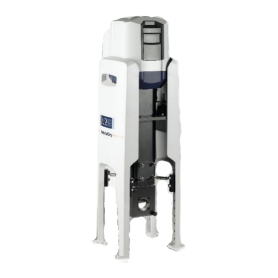
Optical excellence. The OptistatDry BL4 (bottom loading) system provides a temperature controlled sample-in- vacuum measurement environment within a cryofree cryostat (i.e. a cryostat that is cooled by a mechanical refrigerator as opposed to liquid cryogens). The system enables optical and electrical measurements to be carried out on the user’s sample. -
Page 17: Description Of The Optistatdry Bl4 System
OptistatDry BL4 2.1 Description of the OptistatDry BL4 system Figure 2 shows a schematic diagram of the complete OptistatDry BL4 system. Note that some components are optional and may not be supplied with your system. The main components are: The cryostat, consisting of ... - Page 18 Compressor Cryostat and integral cold head Figure 2 Schematic diagram of OptistatDry BL4 system The sample space and radiation shields are thermally isolated from the room temperature surroundings by the OVC. The OVC must be pumped to a high vacuum using an external pumping system before the cryostat is cooled down.
-
Page 19: Optistatdry Bl4 Cryostat Components
The compressed gas lines are attached to the cold head at the rear. Cold head dust cover Side panel (left) Side panel (right) Pressure relief plate Sample access plate Optical window block Outer window assembly Figure 3 OptistatDry BL4 front view Page 15 ©2014 Oxford Instruments Omicron NanoScience. All rights reserved. - Page 20 Note that the front-facing edges of the side panels are wider than those at the rear. Figure 3 and Figure 4 are consistently labelled to show that the right (or left) side panel is on the right (or left) as viewed from the front. Page 16 ©2014 Oxford Instruments Omicron NanoScience. All rights reserved.
-
Page 21: Unpacking And Assembly
December 2014 / UMC0068 OptistatDry BL4 3 UNPACKING AND ASSEMBLY Assembly of the OptistatDry BL4 is a straightforward procedure requiring no specialist training. This chapter describes how to: Decide the best position for your OptistatDry BL4. Unpack and check the OptistatDry BL4 components. -
Page 22: Siting Considerations
When choosing a site for the compressor and cryostat, the following points should be taken into account. Please also follow the advice given in the SHI Helium Compressor Technical Manual. Figure 5 Typical OptistatDry BL4 system set-up Allow enough space so that the helium lines from the compressor can be supported horizontally where they attach to the cold head. - Page 23 2.5 Nm Removal/fitting of DRYTSH and 2.5 Nm DRYRSH sample holders Table 1 Tools required for the OptistatDry BL4 assembly and fitting of parts Tool Where used Removal of shipping bolt underneath compressor 17 mm Spanner or socket + ratchet...
-
Page 24: Unpacking
Remove the internal packing foam layers one by one and take out all the OptistatDry BL4 components except for the cryostat with integral cold head. Leave this in place until required in section 3.3.3. -
Page 25: Fitting The Cryostat To The Vertical Support Stand
The total weight of the cryostat and the vertical support stand is approximately 23kg. This is too heavy for one person to manage safely. All processes that require lifting or moving the partly or fully assembled system require two people. Page 21 ©2014 Oxford Instruments Omicron NanoScience. All rights reserved. -
Page 26: Define The Window Height
(section 3.4.1). Major adjustments can also be made without the need for complete disassembly (section 3.4.2). The tapped holes in the side panels are numbered starting from the top; see Figure 8. Page 22 ©2014 Oxford Instruments Omicron NanoScience. All rights reserved. -
Page 27: Move The Support Cradle To The Correct Height
It is therefore essential to fix the feet of the side panels to an optical bench (or similar) before any height adjustments are made. When the support cradle has Page 23 ©2014 Oxford Instruments Omicron NanoScience. All rights reserved. - Page 28 Remove the four pairs of M6 bolts that fix the support cradle to the side panels. Ensure that you hold the cradle before removing the last M6 bolt. Imperial Metric Figure 10 OptistatDry BL4 DRYSTDV support stand cradle and feet Page 24 ©2014 Oxford Instruments Omicron NanoScience. All rights reserved.
-
Page 29: Fit The Cryostat To The Vertical Support Stand
OptistatDry BL4 Raise or lower the support cradle and re-bolt it to the side panels at the required height. Figure 11 OptistatDry BL4 DRYSTDV support stand cradle adjustment 3.3.3 Fit the cryostat to the vertical support stand In all cases, for safety and handling reasons, the support stand must be placed on a level floor with unrestricted access all around before the cryostat can be loaded into it. - Page 30 Place one hand under the lower cold head cover to facilitate a stable vertical lift. Do not attempt to lift the cryostat vertically using any part of the white cold-head cover. Figure 14 OptistatDry BL4 DRY- do NOT lift from the cover Page 26...
- Page 31 This operation requires two persons. One person should be responsible for lifting and fitting the cryostat to the frame and the other person responsible for guiding the installation. Page 27 ©2014 Oxford Instruments Omicron NanoScience. All rights reserved.
- Page 32 The lower fine adjustment nuts at the rear of the cryostat should be wound approximately 3mm Page 28 ©2014 Oxford Instruments Omicron NanoScience. All rights reserved.
-
Page 33: Cryostat Height Adjustments
Finally, for each mount, hold the lower nut stationary with an open-ended spanner and turn the upper nut with another open-ended spanner until it is tight against the bracket. Page 29 ©2014 Oxford Instruments Omicron NanoScience. All rights reserved. -
Page 34: Major Adjustments
Note that the stand must be securely bolted to the optical table before attempting this procedure. Figure 21 Support the weight with a laboratory jack Support the weight of the cryostat using a laboratory jack, as shown. Page 30 ©2014 Oxford Instruments Omicron NanoScience. All rights reserved. -
Page 35: Fitting Cryostat Radial Restraints
The cryostat has been adjusted for vertical alignment within the frame. Fit cryostat supports only when the side panels are securely bolted to the optical bench and all eight cradle fixing bolts are tightened. Page 31 ©2014 Oxford Instruments Omicron NanoScience. All rights reserved. - Page 36 Position the four locator blocks on the side panel legs (using two M6 x 25mm bolts per block) so than one of the three location holes is approximately opposite the locator studs. Figure 24 Locator blocks Page 32 ©2014 Oxford Instruments Omicron NanoScience. All rights reserved.
- Page 37 Using a small Allen key (or similar tool) to prevent the adjustable pins from rotating, increase the length of each radial restraint by turning the barrels using your fingers until all the radial restraints fit securely. Page 33 ©2014 Oxford Instruments Omicron NanoScience. All rights reserved.
- Page 38 10mm A/F open ended spanner, to fix the overall length. Figure 28 Fix the final length of the radial constraints Do not try to over-extend the restraints. It is enough that the elastomer inside each restraint is slightly compressed. Page 34 ©2014 Oxford Instruments Omicron NanoScience. All rights reserved.
-
Page 39: Making The Compressor Ready
Failure to observe this warning can result in serious injury or death. Page 35 ©2014 Oxford Instruments Omicron NanoScience. All rights reserved. -
Page 40: Connect Helium Gas Lines To Cold Head
The supply line should be restrained as close as is practically possible to the cold head. Ideally, the restraint should take the form of a rubber lined clamp that conforms to the profile of the line without crushing or damaging it. Page 36 ©2014 Oxford Instruments Omicron NanoScience. All rights reserved. - Page 41 However, it is important to ensure that the lines are correctly labelled at each end to avoid incorrect connection between the compressor and the cold head. Page 37 ©2014 Oxford Instruments Omicron NanoScience. All rights reserved.
- Page 42 Figure 33 Make the helium line connections to the compressor Then support the other end of lines as described previously before making the connections to the cold head. Page 38 ©2014 Oxford Instruments Omicron NanoScience. All rights reserved.
-
Page 43: Temperature Monitoring And Control System
3.8 Temperature monitoring and control system 3.8.1 Set up the temperature controller If you have bought a cryostat and temperature controller together from Oxford Instruments the temperature controller will have been set up in the factory in order to ... -
Page 44: Connect The Temperature Controller
If you are using another temperature controller, you will need to construct a suitable cable using the wiring information for the 15 way micro D connector given in Appendix A. Page 40 ©2014 Oxford Instruments Omicron NanoScience. All rights reserved. -
Page 45: First Test
4 FIRST TEST 4.1 Introduction This section describes how to cool the OptistatDry BL4 to base temperature for the first time with blanking pieces fitted to the radiation shield openings and the OVC window mounts. The first test sequence includes running the system to base temperature, controlling the sample position at 300K and then warming the entire system to room temperature. -
Page 46: Vent The Cryostat And Remove The Sorption Pump
Lift up the radiation shield plate and remove it so that the sorption pump can be conditioned, as described in section 4.3 below. Figure 37 Remove radiation shield plate Page 42 ©2014 Oxford Instruments Omicron NanoScience. All rights reserved. -
Page 47: Condition The Sorption Pump And Close Up System
The temperature of the shield plate and integral sorption pump should not be allowed to exceed 110°C. Figure 38 Radiation shield plate with integral sorption pump on laboratory hot plate Page 43 ©2014 Oxford Instruments Omicron NanoScience. All rights reserved. - Page 48 The radiation shield plate should be hot when it is bolted into place. Take suitable precautions to ensure safe handling. Figure 39 Replace radiation shield plate The bolts should be tightened to a torque ~1.0Nm. Page 44 ©2014 Oxford Instruments Omicron NanoScience. All rights reserved.
-
Page 49: Pump Out The Cryostat
Refer to the operating instructions supplied with the pump for details of how to operate. Optional turbo pumps supplied by Oxford Instruments (H4-600 or H4-601) have their own manuals. Connect a suitable pumping system to the cryostat pumping port using a suitable length of 25mm diameter flexible stainless steel pumping line. -
Page 50: Start Up The Compressor
This is the pressure indicated on a gauge connected directly to the cryostat pumping port (see Figure 4). The H4-601 optional turbo pump from Oxford Instruments has its own gauge. The cryostat should be pumped for a minimum of 2 hours using any of the optional turbo pumps supplied by Oxford Instruments. -
Page 51: Control The Sample Region At 300K
Operate the switch on the rear panel of the Mercury so that the 1 is depressed. Press the Power button on the left of the front panel. The button illuminates blue. Page 47 ©2014 Oxford Instruments Omicron NanoScience. All rights reserved. -
Page 52: Temperature Control Above Base Temperature
Derivative action time (D). Note that MercuryiTC uses units of minutes. For more information on PIDs and temperature control please refer to the MercuryiTC temperature controller manual section 14. Tap Control on the home screen to give the following screen. Page 48 ©2014 Oxford Instruments Omicron NanoScience. All rights reserved. -
Page 53: Fit Optical Windows
PID values are given in the MercuryiTC manual. 4.9 Fit optical windows The OptistatDry BL4 is supplied with plastic blanks fitted on all window mounts. Windows are supplied separately in protective packaging. A wide range of window materials is available for the OptistatDry BL4. This section describes how to remove blanks and fit or change windows. - Page 54 OVC. Remove the four M3 nylon screws that hold the window/blank in place. Remove the window/blank. A vacuum tool (such as the Oxford Instruments DRYLOAD) or plastic tweezers can be helpful.
-
Page 55: Normal Operation
December 2014 / UMC0068 OptistatDry BL4 5 NORMAL OPERATION This chapter describes normal operation of the OptistatDry BL4, including sample changing. 5.1 Introduction to normal operation If you have DRYRSH or DRYTSH (standard) sample holders, read sections 5.2 and 5.5. - Page 56 Start up the compressor and cool the cryostat (section 4.5). Control temperature (section 4.8.2) and collect data. Switch off compressor, set the sample temperature to control at 300K and allow cryostat to warm up for sample change (section 4.7). Page 52 ©2014 Oxford Instruments Omicron NanoScience. All rights reserved.
-
Page 57: Fitting And Removing The Standard Sample Holder
~1.0Nm. Lift up the plate and remove it, storing carefully. Figure 44 Remove radiation shield plate Page 53 ©2014 Oxford Instruments Omicron NanoScience. All rights reserved. - Page 58 Fit the sample holder, reversing the procedure described above. The sample plate bolts should be tightened to a torque ~2.5Nm to provide good thermal contact. Page 54 ©2014 Oxford Instruments Omicron NanoScience. All rights reserved.
-
Page 59: Electrical Connection Via The Drylx20 Connector
Please take care when making and breaking this connection so as not to bend the pins on the mating connector. More details can be found in Appendix A4. Page 55 ©2014 Oxford Instruments Omicron NanoScience. All rights reserved. -
Page 60: Fitting And Removing The Optical Tail For Greater Access
When the window block is refitted the bolts should be tightened to a torque ~1.8Nm. Figure 47 Remove Torx bolts in OVC body Page 56 ©2014 Oxford Instruments Omicron NanoScience. All rights reserved. - Page 61 Figure 49 Remove Torx bolts in radiation shield tail Remove the radiation shield tail and store carefully in a clean, dry, sealed bag. There is now access to the sample region. Page 57 ©2014 Oxford Instruments Omicron NanoScience. All rights reserved.
-
Page 62: Fitting The Puck Sample Holder
There is no need to remove the screws completely; two or three turns is usually sufficient. Use the DRYLOAD tool as described above. Page 58 ©2014 Oxford Instruments Omicron NanoScience. All rights reserved. -
Page 63: Condition The Sorption Pump And Close Up System
The sample puck bolts should be tightened to a torque of approximately1.0Nm. 5.5 Condition the sorption pump and close up system Follow the steps detailed in section 4.3. 5.6 Pump out the cryostat Follow the steps detailed in section 4.4. Page 59 ©2014 Oxford Instruments Omicron NanoScience. All rights reserved. -
Page 64: Start Up The Compressor
Follow the steps detailed in section 4.8. 5.9 Warm up for sample change Follow the steps detailed in section 4.7 in order to warm the cryostat ready for sample change. Page 60 ©2014 Oxford Instruments Omicron NanoScience. All rights reserved. -
Page 65: Maintenance And Servicing
Compressor adsorber 30,000 hours Order: C10-034 Oxford Instruments offer service contracts for maintaining the OptistatDry BL4 and would be happy to discuss requirements with you. Please consult us for more information. 6.3 Cryostat O-rings We recommend replacing the cryostat O-rings on a two year cycle, with the sample loading door O-ring being replaced on an ad-hoc basis. -
Page 66: Gm Cold Head And Compressor Maintenance
The adsorber replacement and helium gas charging procedures are described in the SHI Helium Compressor Technical Manual. Oxford Instruments offers on-site installation of service exchange cold heads and compressor adsorbers. Please consult us for service contract details and more information. -
Page 67: Troubleshooting
SHI SRDK-101D-HC4A2 (or HC4E2) Cryocooler Operation Manual. Diagnosis of MercuryiTC temperature controller faults should be made using the MercuryiTC manual Troubleshooting chapter. Use the following table to examine problems that can arise from the OptistatDry BL4 cryostat or a combination of the above. Problem... - Page 68 Page 64 ©2014 Oxford Instruments Omicron NanoScience. All rights reserved.
-
Page 69: Appendix A Technical Data
Item Specification Width 240 mm Depth (excluding gas lines to cold head) 290 mm Height 635 - 900mm (adjustable) Weight with vertical support stand 23 kg Page 65 ©2014 Oxford Instruments Omicron NanoScience. All rights reserved. -
Page 70: A3 Wiring Of 15 Way Micro D Connector To Sample Heater And Thermometer
40W / 40V Firerod twisted pair heater Pin 11 - 40Ω Heater I- Not used Not used Not used Not used Not used Not used Not used Not used Not used Page 66 ©2014 Oxford Instruments Omicron NanoScience. All rights reserved. -
Page 71: A4 Wiring Of Optional 21 Way Micro D Connector To Drylx20
Copper 36 SWG constantan 42 SWG wiring and one twisted pair twisted pair of copper 36 SWG wires. Not used Page 67 ©2014 Oxford Instruments Omicron NanoScience. All rights reserved. -
Page 72: Appendix B Sample Puck Options
(a 4mm diameter opening) with 12 DC connections for customer use. Pin 12 Pin 1 Pin 11 Pin 21 Figure 57 Pin numbering on the hermetic 21 way micro D connector flange Page 68 ©2014 Oxford Instruments Omicron NanoScience. All rights reserved. - Page 73 DRYPUCK12R and DRYPUCK12T are shown in the table above. The internal wiring between these terminations consist of five twisted pairs of constantan 42 SWG wires and one twisted pair of copper 36 SWG wires. Page 69 ©2014 Oxford Instruments Omicron NanoScience. All rights reserved.
-
Page 74: Customer Support
Telephone: +81 (0)3 6722 8966 Email: nanoscience.jp@oxinst.com Web: www.oxford-instruments.com China Oxford Instruments China Room 714, Tower 3, Henderson Centre, No. 18, Jianguomennei Avenue, Beijing, 100005 Telephone: +86 10 6518 8160 E-mail info@oxford-instruments.com.cn Web: www.oxford-instruments.com Page 70 ©2014 Oxford Instruments Omicron NanoScience. All rights reserved.
Need help?
Do you have a question about the OptistatDry BL4 and is the answer not in the manual?
Questions and answers