
Related Manuals for Oxford Instruments NanoScience Optistat DN-V


Summary of Contents for Oxford Instruments NanoScience Optistat DN-V
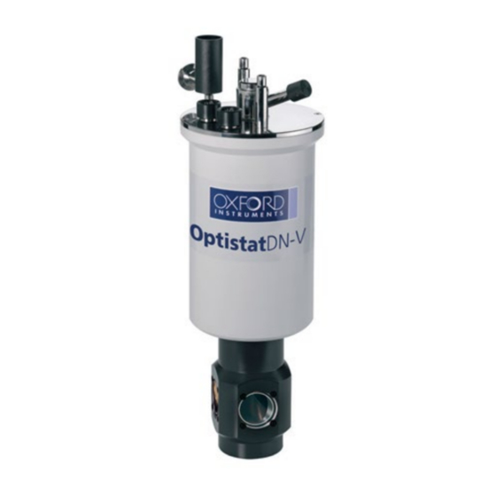
- Page 1 Oxford Instruments NanoScience Optistat DN-V Operators Manual System Manual Issue 2.0 December 2020 nanoscience.oxinst.com © Oxford Instruments Nanotechnology Tools Limited, 2016. All rights reserved.
- Page 2 P a g e...
-
Page 3: Table Of Contents
Contents Introduction ............................ 5 Copyright ..........................5 Statement of intended use ..................... 6 Restrictions on use ........................6 Maintenance and adjustment ....................6 Warranty ..........................6 Acknowledgements ......................... 6 Technical support ........................7 Health and safety ..........................8 Disclaimer ..........................8 Disposal and recycling instructions .................. - Page 4 Sensor calibrations ........................ 17 System components and layout .................... 18 Weights and dimensions ....................... 18 System installation ........................19 Unpacking the system ......................19 Preparing the system for operation ..................19 Loading the sample ....................... 19 Evacuating the OVC ....................... 19 Connecting to the MercuryiTC temperature controller ............
- Page 5 P a g e...
-
Page 6: Introduction
Oxford Instruments be liable for direct or indirect loss or damage of any kind, including loss of profit, revenue, goodwill or anticipated savings. All such warranties are hereby excluded to the fullest extent permitted by law. -
Page 7: Statement Of Intended Use
Use of the equipment for purposes other than those intended and expressly stated by Oxford Instruments, as well as incorrect use or operation of the equipment, may relieve Oxford Instruments or its agent of the responsibility for any resultant non-compliance damage or injury. The system must only be used with all external covers fitted. -
Page 8: Technical Support
Technical support If you have any questions, please direct all queries through your nearest support facility (see below) with the following details. Please contact Oxford Instruments before attempting to service, repair or return components. System type: Optistat DN-V Serial number: The Sales Order (SO) number and/or other identifiers of your system. -
Page 9: Health And Safety
Disclaimer Oxford Instruments assumes no liability for use of any document supplied with the system if any unauthorised changes to the content or format have been made. Oxford Instruments' policy is one of continued improvement. The company reserves the right to alter without notice the specification, design or conditions of supply of any of its products or services. -
Page 10: Rohs Compliance
All the materials and components used in the manufacture of the Optistat DN-V are in compliance without exemption with the EU Directive 2011/65/EU for Restrictions of Hazardous Substances (RoHS). This is based on information provided by Oxford Instruments suppliers and is accurate to the best of our knowledge. -
Page 11: Low Temperatures
PROTECTIVE EARTH The cryostat and any other parts of the system fitted with earthing points must always be connected to protective earth during operation. Parts of the system carry high voltages that can cause death or serious injury. Ensure that a local electrical earth (ground) connection is available. -
Page 12: Weight And Lifting
Figure 2-1: The pressure relief valve on the Optistat DN-V. Do not modify or tamper with these safety features in any way. Additionally, ensure that nothing can restrict the movement of any of the pressure relief valves. The relief valves should not vent during normal operation of the system. -
Page 13: Trip Hazards
2.5.7 Trip hazards TRIP HAZARDS Poorly routed cables and pumping lines can be trip hazards and have the potential to cause accidents. Such accidents can result in both damage to the system and injury to personnel. Where cables and lines are required, their routings should be considered when planning the installation of the system. -
Page 14: Risk Assessments
• Hazard warning signs, barriers or controlled entry systems to ensure that personnel approaching the system are aware of the potential hazards. This precaution is especially important if your system includes a superconducting magnet. • Oxygen monitors should be fitted in the laboratory to warn personnel if the concentration of oxygen in the air falls below safe levels. -
Page 15: System Description
System description The Optistat DN-V is a liquid nitrogen cryostat and can be held at temperatures between 77 K and 500 K using a MercuryiTC temperature controller. A sample can be mounted on a sample holder which is thermally linked to the system’s heat exchanger providing cooling during operation. Up to five windows can be fitted to the Optistat DN-V providing optical access to the sample holder with an optical f number of 1.0. -
Page 16: Sample Holders
Figure 3-1 Optistat DN-V cryostat schematic. Sample holders There are two sample holders supplied with the Optistat DN-V. The first is a plain reflectance sample holder, as shown in Figure 3-2 (Left), several small samples can be mounted on to this sample holder at once. -
Page 17: The Mercuryitc Temperature Controller
The MercuryiTC temperature controller A MercuryiTC is used as the temperature controller for the system. The MercuryiTC monitors and controls the thermometry of the system and adjusts the system’s heater voltage to hold the sample holder at a defined temperature. The MercuryiTC is configured with measurement cards in specific locations. -
Page 18: Sensor Calibrations
The experimental connector is wired to the Harwin pin ring above the sample holder. The pin configuration for the 16-pin Harwin pin ring is shown in Figure 3-4. On the Optistat DN-V, pin one of the Harwin pin ring is denoted by a black dot. Figure 3-4: Pin configuration for the 16-pin Harwin pin ring. -
Page 19: System Components And Layout
Specification Value Temperature Range 70 - 900 K Stability/year 130 mK Reproducibility 60 mK 100 Ω at 273 K Nominal Resistance 138.5 Ω at 373 K Table 3-4: Platinum resistance thermometer temperature / resistance relationship. File “RP51.dat” is provided with the system information on your USB stick. This file contains the generic calibration data for the PT100 sensor. -
Page 20: System Installation
Carefully remove the cryostat and all the accessories from the packing case and check the packing list to make sure that you have all the components. Examine the system to make sure that it has not been damaged since it left the factory. If you find any signs of damage, please contact Oxford Instruments immediately. -
Page 21: Connecting To The Mercuryitc Temperature Controller
Connecting to the MercuryiTC temperature controller The MercuryiTC has been configured by Oxford Instruments to suit the ordered system. When you first switch on the MercuryiTC, you will see the instrument home screen, similar to the screen shown in Figure 4-1. - Page 22 On the MercuryiTC home screen, tap ‘Heater’. The screen shown in Figure 4-2 will be displayed. • Tap ‘Resistance Set’ and change the resistance value to 150 Ω. • Tap ‘Voltage’ and change this to 12 V. • Tap ‘Home’ to return to the home screen. Figure 4-2: MercuryiTC heater window.
- Page 23 During normal operation, up to 40 V is applied across the 20 Ω heat exchanger heater. Following sorb reconditioning, ensure that the voltage limit is adjusted as follows: • On the Mercury iTC home screen, tap ‘Heater’. • Tap ‘Resistance Set’ and change the resistance to the value given in the test results. This will be about 20 Ω.
-
Page 24: System Operation
5 System operation This section describes the operation of the Optistat DN-V in conjunction with an Oxford Instruments MercuryiTC temperature controller. The cryostat can be operated manually if a temperature controller is not available, although it may be difficult to obtain good temperature control in this configuration. -
Page 25: Operation At Base Temperature
Slowly pour liquid nitrogen into the reservoir. The liquid will boil violently at first, before suddenly dropping off. Fill the reservoir until liquid comes out of the vent tube. LIQUID NITROGEN CONTAMINATION Ensure that the nitrogen supply is free from contaminants such as frozen particles. This will reduce the risk of blockages in the heat exchanger capillary tube. - Page 26 Figure 5-2: MercuryiTC ‘Control’ screen. Tapping ‘PID table’ in the bottom left will display a screen like the one shown in Figure 5-3. This screen shows the current PID table loaded into the MercuryiTC. In this case, ‘Optistat DN Mercury.pid’ should already be loaded into the MercuryiTC.
-
Page 27: Controlling At A Set Temperature
Figure 5-4: MercuryiTC ‘select file’ screen for loading alternative PID tables. The PID values given in the test results for the system are suitable to give good stability. If you wish to improve the stability further, you may be able to do this by adjusting the three terms slightly. In Manual mode, individual PID values can be changed during operation. -
Page 28: Changing The Sample
Changing the sample A sample within the Optistat DN-V can only be changed by warming the whole cryostat to room temperature, as described in Section 5.8. Then venting cryostat and removing the OVC to gain access to the sample space, as described in Section 5.9. Warming up the system If you do not need to warm the system quickly, it may be left to warm up naturally. -
Page 29: Changing Sample Holders
OVC REPLACEMENT When replacing the OVC, ensure no internal wiring from the cryostat touches the OVC. Such a touch will reduce the performance of the system. After removing the system’s OVC, ensure you recondition the sorb before cooling the system again. 5.10 Changing sample holders To change the sample holder affixed to the sample stage, the cryostat OVC must first be removed, this... - Page 30 Figure 5-6: Changing the OVC windows. To replace an OVC window, carefully remove the four retaining nylon screws around the edge of the window, taking care to ensure the window does not fall out by itself when removing the screws. The window can then be removed.
-
Page 31: Service And Maintenance
O-rings Oxford Instruments recommends replacing the cryostat’s O-rings on a two-year cycle. Whenever a part of the cryostat is removed, or if there is a suspected leak on the system, check the relevant O- rings. - Page 32 Issue Possible cause Recommendation Poor cryostat OVC Sorb contaminated Recondition the system sorb as per the vacuum procedure given in Section 4.6. High base Heater still on Check the heater is switched off. temperature Poor vacuum Check the quality of the vacuum in the cryostat. Sensor fault Check sensor resistance at base temperature and compare with the supplied sensor...
-
Page 33: Optistat Dn-V Specifications
7 Optistat DN-V specifications Performance Performance Specification Temperature control range 77 K† - 500 K Temperature control stability ± 0.1 K Liquid nitrogen hold time (at 77 K) 15 hours System cooldown time 20 minutes Electrical power Component Power Consumption Voltage Frequency MercuryiTC temperature controller 450 W... -
Page 34: Appendices
8 Appendices Checking the wiring A resistance meter can be used to check the diagnostic wiring on the cryostat. You should expect to measure the following values. Pins Approx. resistance (at 300K) A - B 15 – 25 Ω C - D 110 –...
Need help?
Do you have a question about the NanoScience Optistat DN-V and is the answer not in the manual?
Questions and answers