Advertisement
OpAL
Open Load Atomic Layer Deposition System
System Manual
Works Order No.:
Customer:
THIS SYSTEM INCORPORATES POTENTIALLY DANGEROUS COMPONENTS, WHICH CAN EXPOSE
PERSONNEL TO HAZARDS RESULTING IN DEATH OR SERIOUS INJURY.
BEFORE ATTEMPTING TO INSTALL, POWER UP OR OPERATE THIS SYSTEM, ENSURE YOU HAVE
READ AND UNDERSTOOD THE ENCLOSED SYSTEM MANUAL, ESPECIALLY SECTION 1 (HEALTH
AND SAFETY).
94-417919
Università di Pisa
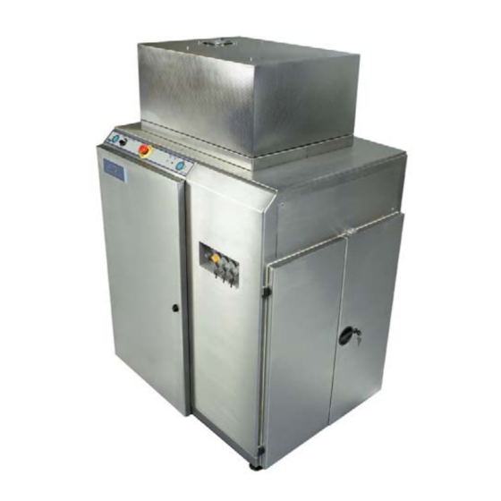
Typical OpAL system
Issue 1: July 2010
WARNING
Advertisement
Chapters

Related Manuals for Oxford Instruments OpAL


Summary of Contents for Oxford Instruments OpAL
- Page 1 Works Order No.: 94-417919 Customer: Università di Pisa Typical OpAL system WARNING THIS SYSTEM INCORPORATES POTENTIALLY DANGEROUS COMPONENTS, WHICH CAN EXPOSE PERSONNEL TO HAZARDS RESULTING IN DEATH OR SERIOUS INJURY. BEFORE ATTEMPTING TO INSTALL, POWER UP OR OPERATE THIS SYSTEM, ENSURE YOU HAVE READ AND UNDERSTOOD THE ENCLOSED SYSTEM MANUAL, ESPECIALLY SECTION 1 (HEALTH AND SAFETY).
- Page 2 OEM Manuals Notes: Please regard this manual as part of the system. Ensure that any amendment received is incorporated in the text. Oxford Instruments Plasma Technology Yatton, Bristol, BS49 4AP Tel: +44 1934 837000 Fax: +44 1934 837001 Issue 1: July 2010...
-
Page 3: Table Of Contents
System Readiness Form QCF 89 Declaration of Conformity QCF 185d ASM Patent Rights 1. Health and Safety ....................1-1 2. Services (OpAL) ..................... 2-1 3. Description ......................3-1 4. Installation......................4-1 5. Operating Instructions ..................5-1 6. Maintenance ......................6-1 7. -
Page 4: Preface
Refer to manual Customer Support Facilities Oxford Instruments Plasma Technology has global Customer Support Facilities to provide a co-ordinated response to customer’s queries. All queries are recorded on our Support Database and dealt with as quickly as possible. If we are not able to answer the query immediately, we will contact you as soon as possible. -
Page 5: System Identification
System Manual OpAL Oxford Instruments Plasma Technology System Identification This system, Works Order No. 94-417919 for Customer: Università di Pisa , is identified by a label attached to the rear of the power box. An image of this label is shown below: NOTE: Refer to the label attached to the system power box for the measured maximum rated input current value. -
Page 6: Goods Return Form Qcf
The equipment has been drained of any lubricant All ports have been sealed and the equipment has been securely packed and labelled in accordance with Oxford Instruments Plasma Technology recommendations (available on request) The carrier has been informed of the nature of the consignment. - Page 7 The above equipment has been examined / tested in my presence, at Oxford Plasma Technology. The following list defines items that need to be actioned prior to final acceptance being given. Witnessed by: Oxford Instruments Plasma Technology representative Signature: Date: Accepted by: Representative of the end user.
- Page 8 Date: Please ask our representative for a copy of our Customer feedback form, in order that you may record your opinions of the service given by Oxford Plasma Technology Ltd. Witnessed by: Oxford Instruments Plasma Technology representative Signature: Date: OIPT circulation:...
-
Page 9: System Readiness Form Qcf
Should this form be received, an engineer dispatched to start commissioning and any of the facilities requirements not be met, Oxford Instruments reserves the right to terminate that commissioning visit and charge the customer for a return visit, once the facilities have been fully completed. - Page 10 QCF89 issue 8 09/11/07 Environmental Agency Producers Registration Number for WEEE: WEE/AE0116XU between inlet and outlet must be 3 - 4 Bar (45 – 60PSI). Water supply Pressure Pressure should be connected to each inlet/outlet on the system in parallel and not series.
- Page 11 QCF89 issue 8 09/11/07 Environmental Agency Producers Registration Number for WEEE: WEE/AE0116XU in the gas pod is connected, available for process and that Gas 1 Gas 7 the gas line has been leak checked. Please record the leak rate for each gas line. If there is no Gas 2 Gas 8 line fitted please enter N/A.
- Page 12 QCF89 issue 8 09/11/07 Environmental Agency Producers Registration Number for WEEE: WEE/AE0116XU 20.a. Please state, which processes require to be demonstrated. 20.b. Are the required samples and measurement equipment available for the process work to follow on from hardware acceptance? Name : Position Within Company: Signature:...
- Page 13 QCF89 issue 8 09/11/07 Environmental Agency Producers Registration Number for WEEE: WEE/AE0116XU Please return the completed form to your nearest Oxford Instruments Support Office, detailed below: USA & Canada DE, NE, B, SE, FI,DK Eastern Territories U.K. and all Other Territories...
-
Page 15: Asm Patent Rights
lé^i== lñÑçêÇ=fåëíêìãÉåíë=mä~ëã~=qÉÅÜåçäçÖó System Manual ^pj=m~íÉåí=oáÖÜíë= This product exploits technology that is licensed from ASM and is protected by patents. A label is attached to the system base unit indicating that the ASM licence covers the system: Details of the specific patent numbers are listed in the following 13 pages. ASM Patent Rights Issue 1: July 2007 Printed: 09 October 2007 11:14... - Page 16 ASM Patents Licensed / Sub-Licensed to Oxford Instruments Case Extension Title ApplicationNo FilingDate PublicationNo Publication Date PatentNo Issue Date Status Assgnee g.002 Method for forming a metal film KR 1998/35911 01-Sep-1998 2000/18353 06-Apr-2000 332364 30-Mar-2002 Issued ASMG g.004 Method for forming a three component...
- Page 17 LPCVD with ALD preconditioning EP 1952051.9 09-Jul-2001 1299572 09-Apr-2003 1299572 21-Jul-2004 Published& ASMI I.052 LPCVD with ALD preconditioning 09-Jul-2001 1299572 09-Apr-2003 1299572 21-Jul-2004 Issued ASMI Restricted Distribution Page 2 of 13 SM Patents Licensed / Sub-licensed to Oxford Instruments October 14, 2005...
- Page 18 MC.005 PCT Pump between pulses WO /FI95/00658 28-Nov-1995 9617107 06-Jun-1996 Published ASMI MC.006 AUS Flow restriction US 08/682703 26-Jul-1996 27-Jan-1998 5711811 27-Jan-1998 Issued ASMI Restricted Distribution Page 3 of 13 SM Patents Licensed / Sub-licensed to Oxford Instruments October 14, 2005...
- Page 19 Single wafer ALCVD™ reactor US 10/383291 06-Mar-2003 2003/0150385 14-Aug-2003 Published ASMI MC.012 EP Single wafer ALCVD™ reactor EP 00660085.2 10-May-2000 1052309 15-Nov-2000 Published ASMI Restricted Distribution Page 4 of 13 SM Patents Licensed / Sub-licensed to Oxford Instruments October 14, 2005...
- Page 20 Ozone for silicon/metal oxides JP 2001/542604 04-Dec-2000 2003/515674 07-May-2003 Published ASMI MC.017 KR Ozone for silicon/metal oxides KR 10/2002/7006 30-May-2002 2002/63196 01-Aug-2002 Published ASMI Restricted Distribution Page 5 of 13 SM Patents Licensed / Sub-licensed to Oxford Instruments October 14, 2005...
- Page 21 MC.024 GB Tungsten nitride GB 09695966 15-Mar-2002 1242647 25-Sep-2002 1242647 18-Aug-2003 Issued ASMI MC.024 JP Tungsten nitride JP 2001/529476 15-Apr-2002 2003/511561 25-Mar-2003 published ASMI Restricted Distribution Page 6 of 13 SM Patents Licensed / Sub-licensed to Oxford Instruments October 14, 2005...
- Page 22 TW 89122263 23-Oct-2000 548239 21-Aug-2003 185773 14-Jan-2004 Issued ASMI MC.030 AUS Solid source for Pulsar™ US 09/854706 14-May-2001 2001/0042523 22-Nov-2001 6699524 02-Mar-2004 Issued ASMI Restricted Distribution Page 7 of 13 SM Patents Licensed / Sub-licensed to Oxford Instruments October 14, 2005...
- Page 23 US 09/866156 24-May-2001 2001/0028924 11-Oct-2001 6652924 25-Nov-2003 Issued ASMI MC.037 D2 CuO reduction / plasma radicals US 10/692243 22-Oct-2003 2004/0083949 06-May-2004 Published ASMI Restricted Distribution Page 8 of 13 SM Patents Licensed / Sub-licensed to Oxford Instruments October 14, 2005...
- Page 24 ASMI MC.044 JP Graded barriers JP 2001/565432 02-Mar-2001 2003/526218 02-Sep-2003 Published ASMI MC.044 PCT Graded barriers WO /US01/06746 02-Mar-2001 0166832 13-Sep-2001 Published ASMI Restricted Distribution Page 9 of 13 SM Patents Licensed / Sub-licensed to Oxford Instruments October 14, 2005...
- Page 25 MC.050 JP Metal oxide reduction JP 2001/584473 15-Nov-2002 2003/533880 11-Nov-2003 Published ASMI MC.050 KR Metal oxide reduction KR 10/2002/7015 13-Nov-2002 2003/7612 23-Jan-2003 Published ASMI Restricted Distribution Page 10 of 13 SM Patents Licensed / Sub-licensed to Oxford Instruments October 14, 2005...
- Page 26 ASMI MC.059 EP Magnetic RAM EP 19952456 26-Nov-2001 1340269 03-Sep-2003 Published ASMI MC.059 PCT Magnetic RAM WO /US01/44350 26-Nov-2001 0245167 06-Jun-2002 Published ASMI Restricted Distribution Page 11 of 13 SM Patents Licensed / Sub-licensed to Oxford Instruments October 14, 2005...
- Page 27 MC.077 EP Low temperature WNC. EP 2798955.7 10-Sep-2002 1425435 09-Jun-2004 Published ASMI MC.077 PCT Low temperature WNC. WO /US02/29032 10-Sep-2002 03025243 27-Mar-2003 Published ASMI Restricted Distribution Page 12 of 13 SM Patents Licensed / Sub-licensed to Oxford Instruments October 14, 2005...
- Page 28 Enhanced CMOS process flow US 10/601037 19-Jun-2003 2004/0106249 03-Jun-2004 Published ASMI MC.145 AUS HfSiON with one reactor US 10/652851 29-Aug-2003 6818517 16-Nov-2004 Issued ASMI Restricted Distribution Page 13 of 13 SM Patents Licensed / Sub-licensed to Oxford Instruments October 14, 2005...
-
Page 29: Health And Safety
A l’attention des clients de langue française Le document hygiène et securité est disponible en français. Vous devez vous assurer que cette version est présente dans ce manual. Si elle est manquante, contactez votre representant Oxford Instruments Plasma Technology. Für deutschsprachige Kunden besteht dieses Kapitel “Health and Safety”... -
Page 30: Health And Safety
If the equipment is used in a manner not specified by Oxford Instruments Plasma Technology, the protection provided by the equipment may be impaired. -
Page 31: Service Mode
Follow local and national safety procedures to alleviate any risk. If a new process is considered and new materials may result, please consult Oxford Instruments Plasma Technology for further heal th and afety inform ation. - Page 32 Plasmalab and Ionfab Oxford Instruments Plasma Technology Health and Safety Some etching and deposition compounds are toxic during use, and can Process Chemicals leave toxic residues in the system. (sub-section 1.4.9, Some non-plasma cleaning processes, for example wet cleaning, may page 1-15) involve the use of toxic or harmful chemicals.
-
Page 33: Electrical
Health and Safety Oxford Instruments Plasma Technology Plasmalab and Ionfab Specific Hazards 1.4.1 Electrical WARNING HAZARDOUS VOLTAGE - CONTACT CAN CAUSE DEATH, SEVERE INJURY OR BURNS Any work requiring the removal of covers or panels must only be performed by authorised personnel who are aware of the hazards involved. -
Page 34: Electromagnetic Radiation
If a metal grid is not fitted and there is any doubt about whether one should be fitted, yo must check with Oxford Instruments Plasma Technology before proceeding. If the view port has been disassembled then tests must be carried out as described in sub-section 1.3.2.1 above. -
Page 35: Light
The customer should be aware of the fact that view ports are available in glass or quartz. Most view ports on Oxford Instruments Plasma Technology systems are glass but quartz is used in certain applications. Quartz view ports allow much more UV light to pass through than glass does, and so present a greater hazard. -
Page 36: High Temperature
Plasmalab and Ionfab Oxford Instruments Plasma Technology Health and Safety 1.4.4 High Temperature WARNING HOT SURFACES - CLOSE CONTACT CAN CAUSE SERIOUS INJURY AND BURNS Allow sufficient time for heated components (e.g. heated lower electrodes) to cool to room temperature before carrying ou t maintenance. -
Page 37: Gases
Health and Safety Oxford Instruments Plasma Technology Plasmalab and Ionfab 1.4.6 Gases Gases are used in the system for venting and purging (N2), for aiding heat transfer (e.g. helium and for establishing the process environment (i.e. proc ess gases). Process gases used in the system are specified dependent on the process for which the system i esigned. - Page 38 1.4.6.11 Pumps must always be operated in accordance with the manufacturers' manuals and with Oxford Instruments Plasma Technology engineers' training courses. Pumps, when fitted with a nitrogen purging facility, must always be purged during a processing run and for a suitable period after a processing run has finished.
-
Page 39: Precursor Materials
Perform a risk assessment and wear suitable personal protective equipment when working on pre-cursor systems. 1.4.7.2 The effluents of all OpAL and FlexAL systems should be considered toxic. 1.4.7.3 Ensure that effluents are extracted into a safe disposal system. The bore of the extraction pipework must be of a greater internal bore than the pump outlet. -
Page 40: Materials
.4.7.12 Pumps must always be operated in accordance with the ma nufacturers' manuals and with Oxford Instruments Plasma Technology engineers' training courses. Pumps, when fitted with a nitrogen purging facility, must always be purged during a processing run and for a suitable period after a processing run has finished. - Page 41 Health and Safety Oxford Instruments Plasma Technology Plasmalab and Ionfab Consult a competent authority regarding the following items (b) to (e). Wearing sui table protective clothing, remove the O-ring and dispose of it in accordance with local Health and Safety regulations.
- Page 42 Follow local and national safety procedures to alleviate any risk. If a new process is considered and unfamiliar materials may result, please consult Oxford Instruments Plasma Technology for further health and safety information. 1.4.8.7 Gases exhausted from rotary vacuum pumps may contain oil vapour which is carcinogenic.
-
Page 43: Process Chemicals
Assume all such materials are hazardous and wear appropriate personal protective equipment. If a new process generates an unfamiliar material, consult Oxford Instruments Plasma Technology for further health and safety information. -
Page 44: Compressed Air
Oxford Instruments Plasma Technology Health and Safety If a plastic implosion eye-guard is not fitted, or if there is any doubt about the type of eye-guard that is fitted, you must check with Oxford Instruments Plasma Technology before p roceeding. - Page 45 Ensure that the main electrical supply, compressed air, all other gases and the water supply are disconnected before starting maintenance work (Also see sub-section 1.3.9 1.4.13.6 Consult Oxford Instruments Plasma Technology before making any alterations to the system or changing the process gases. Health and Safety...
- Page 46 1.4.13.8 Whenever any component is returned to Oxford Instruments Plasma Technology or any of their agents, it must be accompanied by copies of the Goods Return Form (QCF 60). 1.4.13.9 Never smoke or eat in the 'clean room' or where gases are stored.
- Page 47 Health and Safety Oxford Instruments Plasma Technology Plasmalab and Ionfab Label OIPT Part Number Meaning Location Danger of physical injury Magnetic space 94-G-SUN-ART-073 (particularly for persons outer cover. with pacemakers fitted from the strong magneti field generated by the labelled equipment Caution, hot surface Chamber walls.
- Page 48 Plasmalab and Ionfab Oxford Instruments Plasma Technology Health and Safety Label OIPT Part Number Meaning Location Warns of gas type an Gas pod. WARNING maximum pressure connected to the system S ystem vent gas: Nitrogen Max inlet pressure : 5 Bar Warns of gas type an Gas pod.
- Page 49 Health and Safety Oxford Instruments Plasma Technology Plasmalab and Ionfab Label OIPT Part Number Meaning Location Warns of a hazardou Turbo pump 94-G-SUN-ART-052 voltage underneath th controller outer 94-G-SUN-ART-057 cover. cover. Recirculation chiller controller. Three phase filter Warns of hazardous outer cover.
- Page 50 Plasmalab and Ionfab Oxford Instruments Plasma Technology Health and Safety Label OIPT Part Number Meaning Location Warns of the risks o Precursor cabine 94-G-SUN-ART-077 mixing incompatible pre inside and cursors. outside cabinet Warns of the risks o Precursor cabinet 94-G-SUN-ART-065 exposure to hazardou exterior panel.
- Page 51 Health and Safety Oxford Instruments Plasma Technology Plasmalab and Ionfab Label OIPT Part Number Meaning Location Warns that the pump ha Foreline pump. 94-G-SUN-ART-076 been drained of oil and that the pump should n be operat Warns that a filter gaske...
- Page 52 Plasmalab and Ionfab Oxford Instruments Plasma Technology Health and Safety NOTES: Health and Safety Issue 18: April 2010 Page 1-24 of 24 Printed:06 April 2010, 09:32...
- Page 53 2 Services (ALD) ......................2-1 Introduction....................... 2-2 Services ......................2-3 Distribution and use of Nitrogen vent............2-3 2.3.1 Check valve .........................2-3 Fig 2-1: G-SP71B29663 OpAL Services flow diagram..............2-4 Fig 2-2: Hoist pneumatic circuit ....................2-4 Services Page 2-1 of 4 Issue 1: August 07...
-
Page 54: Services (Ald)
System Manual lé^i lñÑçêÇ=fåëíêìãÉåíë=mä~ëã~=qÉÅÜåçäçÖó== fåíêçÇìÅíáçå= The services requirements for lé^i are given in two appendices to this manual: Appendix S Services Specifications for lé^i Systems. This document gives generic information and mandatory requirements for all services. Appendix IDS lé^i Installation Data Sheets. This document gives the information necessary to prepare the environment for the lé^i. -
Page 55: Services
System Manual lñÑçêÇ=fåëíêìãÉåíë=mä~ëã~=qÉÅÜåçäçÖó== lé^i pÉêîáÅÉë= For details of the services required, services panel, etc, refer to Appendix IDS. aáëíêáÄìíáçå=~åÇ=ìëÉ=çÑ=káíêçÖÉå=îÉåí== Nitrogen (N )is supplied to the system via the services panel to allow the process chamber and foreline to be filled during system venting. The N distribution circuit is shown in the services flow diagram;... -
Page 56: Fig 2-1: G-Sp71B29663 Opal Services Flow Diagram
System Manual lé^i lñÑçêÇ=fåëíêìãÉåíë=mä~ëã~=qÉÅÜåçäçÖó== Fig 2-1: G-SP71B29663 OpAL Services flow diagram Fig 2-2: Hoist pneumatic circuit Services Issue 1: August 07 Page 2-4 of 4 Printed: 5-Oct-07, 9:30... - Page 57 System Manual Oxford Instruments Plasma Technology OpAL Description Description ...................... 3-1 Introduction ....................3-3 System component locations..............3-4 3.2.1 Console/base unit mechanical assembly ..........3-4 3.2.2 System views ...................3-5 Hoist assembly ..................3-10 Control system ..................3-13 3.4.1 PC 2000 Hardware and software with licence .........3-13 3.4.2...
- Page 58 Fig 3-31: 94-81-9-21 Standard toxic gas line ............3-37 Fig 3-32: Typical 8-line gas pod................3-40 Fig 3-33: Precursor delivery layout in OpAL ............... 3-42 Fig 3-34: Precursor arrangement inside cabinet............3-43 Fig 3-35: Requirements for connecting bubblers ............3-45 Fig 3-36: Glove box....................
-
Page 59: Description
OpAL Introduction The OpAL system is an Atomic Layer Deposition (ALD) system, which can be configured to carry out thermal (ALD) and plasma enhanced (PEALD). A large range of options is available to precisely tailor the system to the customer's requirements. -
Page 60: Services (Opal)
System Manual OpAL Oxford Instruments Plasma Technology System component locations This sub-section contains illustrations of the OpAL console showing the locations of major system components. 3.2.1 Console/base unit mechanical assembly The system console/base unit is shown in Fig 3-1 (based on drawing G-MA71A30090). -
Page 61: Description
System Manual Oxford Instruments Plasma Technology OpAL 3.2.2 System views The following illustrations show various views of the system. Heat shield Process Chamber Control panel Precursor Cabinet Precursor bypass valves control Fig 3-2: System front view Description Page 3-5 of 46... - Page 62 System Manual OpAL Oxford Instruments Plasma Technology Hoist PLC valve control module PLC temperature control module Relays Fig 3-3: System front view – front panel removed Pumping port Panel for mounting internal CAN (not shown) Extraction port Services panel (Gas, water ,nitrogen,...
- Page 63 System Manual Oxford Instruments Plasma Technology OpAL Water delivery ALD valves Lower electrode heater jacket support flange VAC stat Hoist Gate Valve Pumping pipework ALD valve Water flow switch Purge and Bubbler MFC Internal CAN module N2 ven t valve...
- Page 64 System Manual OpAL Oxford Instruments Plasma Technology Dual valve On/Off heater jacket button Hoist N2 vent supply Water Fig 3-7: Console top front view Fig 3-8: Nitrogen vent line Description Issue 1: August 07 Page 3-8 of 46 Printed: 07 August 2009 07:42...
- Page 65 System Manual Oxford Instruments Plasma Technology OpAL ALD valves mounted behind panel Precursor cabinet door Fig 3-9: Console right-hand view ALD valves Precursor 2 Precursor 4 Precursor 3 Fig 3-10: Console right- hand view (door open) Description Page 3-9 of 46...
-
Page 66: Hoist Assembly
System Manual OpAL Oxford Instruments Plasma Technology Hoist control valves Interface PCB Fig 3-11: Console left hand view showing hoist control valves Hoist assembly The hoist assembly, shown in Fig 3-12, raises and rotates the upper chamber to provide access to the lower chamber and table for wafer handling. The hoist’s pneumatic circuit is shown in Fig 3-13. - Page 67 System Manual Oxford Instruments Plasma Technology OpAL Hoist tube Hoist block Cam tube assembly Pneumatic cylinder Thrust bearing Rod end Fig 3-12: Typical hoist assembly Description Page 3-11 of 46 Issue 1: August 07 Printed: 07 August 2009 07:42...
- Page 68 System Manual OpAL Oxford Instruments Plasma Technology Fig 3-13: Hoist pneumatic circuit Description Issue 1: August 07 Page 3-12 of 46 Printed: 07 August 2009 07:42...
-
Page 69: Control System
The system is controlled and monitored by a Pentium™ PC comprising base unit, keyboard, mouse, 3.5" floppy disk drive, CD-ROM drive and colour monitor. The PC runs a Windows operating system and communicates with the OpAL via an Arcnet communications link. - Page 70 The extensive Oxford Instruments Plasma Technology process library supports all OpAL configurations. A full description of the 'PC 2000' control instructions is provided in Section 5.
-
Page 71: Control Plc (Ald Valves)
System Manual Oxford Instruments Plasma Technology OpAL 3.4.3 Control PLC (ALD valves) The control PLC, shown in Fig 3-15 provides control of the ALD valves. The PLC incorporates a fast microprocessor. Pc2003 Digital I/O B&R Analogue input B&R Analogue output... -
Page 72: Heating
Oxford Instruments Plasma Technology 3.4.4 Heating The management of condensation and decomposition in OpAL is achieved by dedicated temperature control of individual components. Up to 16 temperature zones are available as shown in Fig 3-16 and Table 3-1. Temperature is controlled using PID. - Page 73 System Manual Oxford Instruments Plasma Technology OpAL The heater zones are controlled from the PC 2000 software; a typical heater presets page is shown in Fig 3-17. Fig 3-17: Heater Presets page Description Page 3-17 of 46 Issue 1: August 07...
-
Page 74: Heater Plc
System Manual OpAL Oxford Instruments Plasma Technology 3.4.4.1 Heater PLC The heater PLC, shown in Fig 3-18, controls all heaters except the grounded electrode. The PLC incorporates a dedicated PID, which can control up to 16 temperature zones. PC 2003... -
Page 75: Controls And Indicators
System Manual Oxford Instruments Plasma Technology OpAL Controls and indicators 3.5.1 Base unit The controls and indicators are mounted on the front of the unit as shown in Fig 3-19. Fig 3-19: Controls and indicators The controls and indicators comprise:... -
Page 76: Precursor Cabinet Control Panel
To reset the machine after EMO activation, refer to the procedure given in Section 5. IMPORTANT Where the rotary vane pump is powered from a mains supply separate from the OpAL system, a separate 'Emergency Off' facility must be provided by the customer. -
Page 77: Plc Interlock Chain
System Manual Oxford Instruments Plasma Technology OpAL 3.6.2 PLC interlock chain 3.6.2.1 General description The interlocks form a continuous 24Vdc chain, which must be complete before the process gases and RF power supplies are enabled. An output to disable external devices unless the lid/ hoist is closed is also provided;... - Page 78 System Manual OpAL Oxford Instruments Plasma Technology INTERLOCK DEVICE PCB1 Link out Comments input Vacuum Vacuum Switch BLK17 NONE Pressure below 600 mBar Switch Hoist /Lid Air cylinder BLK18 NONE Lid closed or hoist down. Enables switch/microswitc end point laser via JP51...
- Page 79 System Manual Oxford Instruments Plasma Technology OpAL 3.6.2.2 Gas pod interlocks Refer to drawing: 94-SE81B26657 (PC2003 gas pod loom). To enable process gases, the RF interlock chain must be complete. The gas pod interlock is shown in Fig 3-21. SYSTEM CONSOLE...
-
Page 80: System Link Configuration Table
System Manual OpAL Oxford Instruments Plasma Technology 3.6.2.4 System Link Configuration Table NAME FUNCTION NOTES ANALOGUE 0V TO CHASSIS DIGITAL 0V TO ANALOGUE 0V NON – CONTROLLER CRYO ENABLE HEATER SNAP SWITCH BYPASS FIT IF NO OEM CONTROLLER LK6 A/B... -
Page 81: Process Chamber
System Manual Oxford Instruments Plasma Technology OpAL Process chamber The chamber arrangement is shown in Figs 3-18 to Fig 3-21. The processing chamber is fitted with liners to minimize deposition on the chamber walls. The liners can be removed for maintenance. -
Page 82: Upper Chamber Configuration For Plasma Ald
System Manual OpAL Oxford Instruments Plasma Technology 3.7.1 Upper chamber configuration for plasma ALD The upper chamber configuration for ALD is shown in Fig 3-23 (based on drawing G- MA71A30690). This configuration comprises the following major components: Automatic Matching Unit (AMU) – matches the impedance from the RF generator to the ICP 65 ion source to ensure maximum power transfer. - Page 83 System Manual Oxford Instruments Plasma Technology OpAL Automatic Matching Unit (AMU) Top electrode (ICP 65) Heater jacket for fast gate valve Centering ring O ring Fast gate valve O ring Adapter flange Process gas line O ring Clamping Plasma head...
-
Page 84: Upper Chamber Configuration For Thermal Ald
System Manual OpAL Oxford Instruments Plasma Technology 3.7.2 Upper chamber configuration for thermal ALD The upper chamber configuration for thermal ALD is shown in Fig 3-24 (based on drawing G-MA71A29920). This configuration comprises the following major components: Chamber top cover incorporating a process gas inlet. -
Page 85: Lower Chamber Configuration For Plasma And Thermal Ald
System Manual Oxford Instruments Plasma Technology OpAL 3.7.3 Lower chamber configuration for plasma and thermal ALD The lower chamber configuration for plasma and thermal ALD is shown in Fig 3-25 (based on drawing MA71A29232). Heater Lower chamber cartridge liner Lower process... -
Page 86: Lower Electrode
System Manual OpAL Oxford Instruments Plasma Technology Lower Electrode The lower electrode is shown in Fig 3-26. The electrode is grounded inside the chamber. A flange with allowance for the electrode heater legs and thermocouple leg is fitted to the underside of the chamber. -
Page 87: Vacuum System
System Manual Oxford Instruments Plasma Technology OpAL Vacuum system A typical vacuum schematic for the process chamber, using a 63m3/hr rotary with 2 metres of NW40 flexible stainless steel tubing, is shown in Fig 3-27. The gate valves and isolation valves associated with the pumping systems are pneumatically operated. -
Page 88: System Power Supply
System Manual OpAL Oxford Instruments Plasma Technology 3.10 System power supply The Power Distribution Unit, shown in Fig 3-28, is located at the rear of the unit. It houses circuit breakers and transformers (±15 volt DC and 24 volt DC supplies). The main power supply cable gland and sockets for rotary pumps and auxiliary EMO connection are mounted on the unit. -
Page 89: 94-100-6-46 Icp 65 Source
System Manual Oxford Instruments Plasma Technology OpAL 3.11 94-100-6-46 ICP 65 source The ICP 65 source is shown in Fig 3-29. RF power from the RF generator is fed via the automatch unit to the RF coil to create a plasma within the insulating tube (under vacuum). - Page 90 System Manual OpAL Oxford Instruments Plasma Technology Fig 3-29: ICP 65 source Description Issue 1: August 07 Page 3-34 of 46 Printed: 07 August 2009 07:42...
-
Page 91: Gas Handling
System Manual Oxford Instruments Plasma Technology OpAL 3.12 Gas handling WARNING CONTACT WITH TOXIC GASES CAN CAUSE DEATH OR SERIOUS INJURY. USERS SHOULD PERFORM THEIR OWN RISK ASSESSMENT OF HAZARDOUS GASES TO BE USED ON THE SYSTEM. BEFORE VENTING THE PROCESS CHAMBER, ALWAYS ENSURE THAT THE SYSTEM IS ADEQUATELY PURGED AND PUMPED. -
Page 92: Standard Toxic Gas Line
System Manual OpAL Oxford Instruments Plasma Technology GAS OUT MANIFOLD OUTLET SHUT-OFF VALVE (PNEUMATICALLY CONTROLLED) MASS FLOW CONTROLLER 2 µm FILTER GAS LINE EXTENSION FERRITE CORE GROMMET GAS IN TUBE (STAINLESS STEEL) Fig 3-30: 94-81-9-11 Standard non-toxic gas line 3.12.2 Standard toxic gas line The standard toxic gas line is shown in Fig 3-31. - Page 93 System Manual Oxford Instruments Plasma Technology OpAL Fig 3-31: 94-81-9-21 Standard toxic gas line Description Page 3-37 of 46 Issue 1: August 07 Printed: 07 August 2009 07:42...
-
Page 94: Internal Gas Pod
THE CONNECTION FROM THE GAS POD MANIFOLD TO THE PROCESS CHAMBER SHOULD NOT INCLUDE ANY SHUT OFF VALVE, UNLESS THIS HAS BEEN CLEARED WITH OXFORD INSTRUMENTS PLASMA TECHNOLOGY. A BLOCKAGE HERE COULD CAUSE PROCESS GASES TO MIX AND CROSS CONTAMINATE IN THE HIGH PRESSURE GAS DELIVERY PIPEWORK. -
Page 95: 8-Line Gas Pod
THE CONNECTION FROM THE GAS POD MANIFOLD TO THE PROCESS CHAMBER SHOULD NOT INCLUDE ANY SHUT OFF VALVE, UNLESS THIS HAS BEEN CLEARED WITH OXFORD INSTRUMENTS PLASMA TECHNOLOGY. A BLOCKAGE HERE COULD CAUSE PROCESS GASES TO MIX AND CROSS CONTAMINATE IN THE HIGH PRESSURE GAS DELIVERY PIPEWORK. - Page 96 System Manual OpAL Oxford Instruments Plasma Technology 100MM EXTRACTION COLLAR GAS POD COVER (CUT AWAY TO SHOW INTERNAL DETAILS) PROCESS GAS OUT TO CHAMBER (1) GAS LINE 8 (IN) GAS LINE 7 (IN) GAS LINE 6 (IN) GAS LINE 5...
-
Page 97: Precursor
System Manual Oxford Instruments Plasma Technology OpAL 3.13 Precursor NOTE: Different precursors can be used to deposit the same film. Where possible, OIPT will endeavour to use novel precursors or find alternatives which are safer to handle, use and manage in our systems. - Page 98 System Manual OpAL Oxford Instruments Plasma Technology Fig 3-33: Precursor delivery layout in OpAL Vapour draw is used for delivering high vapour pressure chemicals, category B. This method is used when processing at pressures < vapour pressure of the source chemical at room temperature.
-
Page 99: Water Delivery
System Manual Oxford Instruments Plasma Technology OpAL 3.13.1 Water delivery A water pot is located inside the top console. A pipe connects the pot outlet to the process chamber. A pair of ALD fast valves provides delivery and purging of the line. -
Page 100: Precursor Manufacturers
Table 3-6: Precursor manufacturers Please note the above is not an exhaustive list as Oxford Instruments always recommends you shop around to get the best deal on both price and delivery time, which varies depending on the precursor you are ordering. -
Page 101: Bubbler Connections
165mm and 51mm diameter as shown in Fig 3-35. Please state when ordering the bubbler that it is for an Oxford Instruments machine and the manufacturer should be aware of OIPT’s bubbler specifications. Please see Fig 3-35 for details of these connections. - Page 102 System Manual OpAL Oxford Instruments Plasma Technology 3.14 Glove box The N2 purged glove box, shown in Fig 3-36, is located on the chamber to provide a nitrogen environment for use against moisture and oxygen-sensitive gases. The glove box incorporates: a manual substrate loader ...
-
Page 103: Installation
System Manual Oxford Instruments Plasma Technology OpAL Installation and commissioning Installation and commissioning................4-1 Introduction....................4-2 Installing the system ..................4-2 4.2.1 Unpacking ....................4-2 4.2.2 Positioning the system components............4-3 4.2.3 Connecting the services................4-4 Commissioning the system ................4-6 System adjustments ..................4-7 4.4.1... -
Page 104: Installation And Commissioning
Oxford Instruments Plasma Technology (OIPT) will commission the system. Installing the system The following instructions are a general guide for installing a typical OpAL system, supplied with a remote gas pod and rotary vane pump. Customers should be aware of any special requirements for their specific system, e.g. -
Page 105: Positioning The System Components
System Manual Oxford Instruments Plasma Technology OpAL 4.2.2 Positioning the system components WARNING LIFTING HEAVY OBJECTS INCORRECTLY CAN CAUSE SEVERE INJURY When handling heavy system components such as the system unit or vacuum pumps, ensure that the appropriate lifting equipment, operated by fully trained personnel, is used. -
Page 106: Connecting The Services
System Manual OpAL Oxford Instruments Plasma Technology 4.2.3 Connecting the services IMPORTANT BEFORE CONNECTING ANY OF THE SERVICES, ENSURE THAT THEY ARE NOTES TURNED OFF. E.G. COMPRESSED AIR AND GAS SUPPLY VALVES SET TO THEIR OFF POSITIONS AND ELECTRICAL SUPPLIES SWITCHED OFF AND LOCKED OUT. - Page 107 System Manual Oxford Instruments Plasma Technology OpAL 4.2.3.1 Connecting the 3-phase supply cable to the power box If it is necessary to connect the 3-phase supply cable to the power box, use the following steps. 1) Ensure that the supply cable is not connected to the safety isolation box.
-
Page 108: Commissioning The System
System Manual OpAL Oxford Instruments Plasma Technology Commissioning the system Commissioning of the system will be carried out by OIPT in accordance with their standard procedures and any additional requirements stated in the sales contract. Generally, this will include the following items: Checking that the installation has been carried out satisfactorily. -
Page 109: System Adjustments
DILUTION IS NOT USED TO MAKE THE EXHUAST SAFE TO BREATH: IT MUST STILL BE DUCTED AWAY AND TREATED APPROPRIATELY. If your OpAL system is supplied with a dry pump, e.g. Alcatel ADP122P or ADS602P, that includes its own purge gas monitor, with an output suitable for inclusion in a hardware interlock chain, it is permissible to use this instead of the OIPT purge kit. - Page 110 System Manual OpAL Oxford Instruments Plasma Technology A rotameter is used to set and read the flow. A flow switch monitors the purge. The process gases are turned off by means of a hardware interlock if the flow switch reports low flow below 7.5slpm.
-
Page 111: Operating Instructions
Production mode page ..................5-45 5.10.7 Chamber 1 Process Control page ................5-46 5.10.8 Leak Detection page....................5-51 5.10.9 Mass flow calibration page .................5-53 5.10.10 Tolerances page ....................5-54 Operating Instructions Page 5-1 of 60 Generic (OpAL Plasma) Issue 1: Oct. 07 Printed: 06 November 2007 09:42... - Page 112 Fig 5-18: Chamber 1 process control page ................5-46 Fig 5-19: Leak Detection page ....................5-51 Fig 5-20: Mass flow calibration page..................5-53 Fig 5-21: Process tolerances page ..................5-54 Operating Instructions Generic (OpAL Plasma) Issue 1: Oct. 07 Page 5-2 of 60 Printed: 06 November 2007 09:42...
- Page 113 Power On indicator: Indicates that 3-phase electrical power is connected to the machine. System On indicator: Indicates that the system is powered up. Operating Instructions Page 5-3 of 60 Generic (OpAL Plasma) Issue 1: Oct. 07 Printed: 06 November 2007 09:42...
- Page 114 These screens and menus are introduced as the relevant operation procedures are described in the following sub-sections. A reference guide of all screens is given in sub-section 5.10, page 5-35. Operating Instructions Generic (OpAL Plasma) Issue 1: Oct. 07 Page 5-4 of 60 Printed: 06 November 2007 09:42...
- Page 115 Ensure that the System On LED (located on the system console) is illuminated. Switch the remote PC system controller ON. Operating Instructions Page 5-5 of 60 Generic (OpAL Plasma) Issue 1: Oct. 07 Printed: 06 November 2007 09:42...
- Page 116 Clicking on this button will halt the current process. Also, an Automatic Process Shutdown dialogue is displayed asking you if you wish to shut down the total system. Clicking on Yes will: Operating Instructions Generic (OpAL Plasma) Issue 1: Oct. 07 Page 5-6 of 60 Printed: 06 November 2007 09:42...
- Page 117 Turn off the compressed air supply. Ensure that all heated components have cooled to ambient temperature, then turn off the cooling water. Operating Instructions Page 5-7 of 60 Generic (OpAL Plasma) Issue 1: Oct. 07 Printed: 06 November 2007 09:42...
- Page 118 Process power(s) are turned off as soon as a flow or pressure exceeds a tolerance band - normally within 5 seconds. Operating Instructions Generic (OpAL Plasma) Issue 1: Oct. 07 Page 5-8 of 60 Printed: 06 November 2007 09:42...
- Page 119 MAY BE A SERIOUS GAS HAZARD IN THE CHAMBER AND PUMPING LINES. ASSESS THE RISKS BEFORE TRYING TO PUMP OR VENT THE CHAMBER. PERSONAL PROTECTIVE EQUIPMENT MAY BE NECESSARY. Operating Instructions Page 5-9 of 60 Generic (OpAL Plasma) Issue 1: Oct. 07 Printed: 06 November 2007 09:42...
- Page 120 Press both hoist buttons simultaneously. The chamber lid will lower and rotate. When the chamber lid is fully lowered and rotated, release both hoist buttons. Operating Instructions Generic (OpAL Plasma) Issue 1: Oct. 07 Page 5-10 of 60 Printed: 06 November 2007 09:42...
- Page 121 Ensure that all power scheme options are set to ‘Never’. If necessary, use the drop- down lists to select the ‘Never’ option. Click on the OK button. Close the Control Panel. Operating Instructions Page 5-11 of 60 Generic (OpAL Plasma) Issue 1: Oct. 07 Printed: 06 November 2007 09:42...
- Page 122 Log on as a Manager (see sub-section 5.6.2). Select the System Menu, and then the Password option. The Access Control dialogue box is displayed. Operating Instructions Generic (OpAL Plasma) Issue 1: Oct. 07 Page 5-12 of 60 Printed: 06 November 2007 09:42...
- Page 123 Manager All Facilities automatically enabled. Operating Instructions Page 5-13 of 60 Generic (OpAL Plasma) Issue 1: Oct. 07 Printed: 06 November 2007 09:42...
- Page 124 Note that the enabled facilities are dependent on the name and not on the access level, e.g. two people logged on as users can have different sets of facilities enabled. Operating Instructions Generic (OpAL Plasma) Issue 1: Oct. 07 Page 5-14 of 60 Printed: 06 November 2007 09:42...
-
Page 125: Fig 5-2: Typical System Alert
System Managers only. Clear the alert and log it. Next button: View the next alert. Cancel button: System Managers only. Clear the alert, do not log it. Operating Instructions Page 5-15 of 60 Generic (OpAL Plasma) Issue 1: Oct. 07 Printed: 06 November 2007 09:42... - Page 126 Note the buzzer can be turned ON/OFF by selecting the audible warning button on the status bar (you will be prompted for confirmation). Operating Instructions Generic (OpAL Plasma) Issue 1: Oct. 07 Page 5-16 of 60 Printed: 06 November 2007 09:42...
-
Page 127: Fig 5-3: Pc 2000 Screen Header
The use of the screens will be described in the relevant procedures. Remember that a full description of each screen’s features is given in the PC 2000 Reference Guide. See sub-section 5.10, page 5-35. Operating Instructions Page 5-17 of 60 Generic (OpAL Plasma) Issue 1: Oct. 07 Printed: 06 November 2007 09:42... - Page 128 PARTS OF THE EQUIPMENT MAY BE TOO HOT TO TOUCH. E.G THE PROCESS CHAMBER OPERATES AT 180 ºC AND THE LOWER ELECTRODE (TABLE) OPERATES AT 400 ºC. DO NOT TOUCH THESE COMPONENTS IF THEY ARE HEATED. Operating Instructions Generic (OpAL Plasma) Issue 1: Oct. 07 Page 5-18 of 60 Printed: 06 November 2007 09:42...
- Page 129 Click the START button. (Note that if this button is not active, the chamber has not reached base pressure.) The process will commence. Operating Instructions Page 5-19 of 60 Generic (OpAL Plasma) Issue 1: Oct. 07 Printed: 06 November 2007 09:42...
- Page 130 When the ‘Process Complete’ message is displayed, the system can be vented (see sub-section 5.6.7 page 5-19), or another process run carried out. Operating Instructions Generic (OpAL Plasma) Issue 1: Oct. 07 Page 5-20 of 60 Printed: 06 November 2007 09:42...
- Page 131 You can stop the process at any time; the message ‘Process Complete’ will be displayed, if required, you can then run the same or another process. Operating Instructions Page 5-21 of 60 Generic (OpAL Plasma) Issue 1: Oct. 07 Printed: 06 November 2007 09:42...
- Page 132 Step 5 can be skipped, otherwise load another recipe. On completion of production mode processing, log on as a Manager. Operating Instructions Generic (OpAL Plasma) Issue 1: Oct. 07 Page 5-22 of 60 Printed: 06 November 2007 09:42...
-
Page 133: Fig 5-4: Typical Recipe Page
A recipe is created by adding steps from the Step Library to the Recipe Step Name fields. The recipe is then allocated a Data Log Interval and saved. Operating Instructions Page 5-23 of 60 Generic (OpAL Plasma) Issue 1: Oct. 07 Printed: 06 November 2007 09:42... - Page 134 Select the recipe step from the Step Library list, i.e. click on it to highlight it. Select the DELETE button; the selected recipe step is deleted. Operating Instructions Generic (OpAL Plasma) Issue 1: Oct. 07 Page 5-24 of 60 Printed: 06 November 2007 09:42...
-
Page 135: Fig 5-5: Step Commands Pop-Up Menu
To add a step before an existing step, click on the existing step then select the Insert step button from Step Commands pop-up menu. The selected step and all those Operating Instructions Page 5-25 of 60 Generic (OpAL Plasma) Issue 1: Oct. 07 Printed: 06 November 2007 09:42... - Page 136 The selected step and all those following it will move down the list by one place. You can then drag another step from the Step Library list into the now vacant field. Operating Instructions Generic (OpAL Plasma) Issue 1: Oct. 07 Page 5-26 of 60 Printed: 06 November 2007 09:42...
-
Page 137: Fig 5-6: Typical Select Log Page
The page comprises a list of logged events, which can be filtered by type, batch name and time. When the required events have been selected, they can be viewed on a Log View page. Operating Instructions Page 5-27 of 60 Generic (OpAL Plasma) Issue 1: Oct. 07 Printed: 06 November 2007 09:42... - Page 138 Any logged process run can be saved at text and then opened in Excel for viewing, analysing, etc. To do this, use the following steps: Operating Instructions Generic (OpAL Plasma) Issue 1: Oct. 07 Page 5-28 of 60 Printed: 06 November 2007 09:42...
- Page 139 In the ‘Delimiters’ panel, select the ‘Comma’ checkbox. Select the Next > button. The ‘Text Import Wizard – Step 3 of 3’ dialogue is displayed: Operating Instructions Page 5-29 of 60 Generic (OpAL Plasma) Issue 1: Oct. 07 Printed: 06 November 2007 09:42...
- Page 140 Finish button. The process run log data is now displayed in the Excel worksheet. Adjust the column widths so that all text is visible and then save the spreadsheet. Operating Instructions Generic (OpAL Plasma) Issue 1: Oct. 07 Page 5-30 of 60 Printed: 06 November 2007 09:42...
-
Page 141: Fig 5-7: Typical Run Log Page
The list can also be scrolled vertically to display further steps (for multi-step recipes). Operating Instructions Page 5-31 of 60 Generic (OpAL Plasma) Issue 1: Oct. 07 Printed: 06 November 2007 09:42... -
Page 142: Fig 5-8: Typical Leak Detection And Mfc Calibration Log Page
Log panel. The graph can be scaled in each axis by the controls located at the bottom-left corner of the graph. Operating Instructions Generic (OpAL Plasma) Issue 1: Oct. 07 Page 5-32 of 60 Printed: 06 November 2007 09:42... -
Page 143: Fig 5-9: N 2 Pressure Regulator/Gauge
Refit all system covers. Carry out a simple process to check that the vent sequence operates correctly. Operating Instructions Page 5-33 of 60 Generic (OpAL Plasma) Issue 1: Oct. 07 Printed: 06 November 2007 09:42... - Page 144 If adjustment is necessary, refer to Appendix R in this manual. Operating Instructions Generic (OpAL Plasma) Issue 1: Oct. 07 Page 5-34 of 60 Printed: 06 November 2007 09:42...
-
Page 145: Fig 5-10: Typical Pump Control Page
Fig 5-10: Typical Pump Control page The Pump Control page provides control and monitoring of the vacuum system. The page has the following features: Operating Instructions Page 5-35 of 60 Generic (OpAL Plasma) Issue 1: Oct. 07 Printed: 06 November 2007 09:42... -
Page 146: Fig 5-11: Pump Control Page Vacuum Mimic
Fig 5-11: Pump control page vacuum mimic Valves are coloured Red when closed and Green when open. Running pumps are indicated by animation. Operating Instructions Generic (OpAL Plasma) Issue 1: Oct. 07 Page 5-36 of 60 Printed: 06 November 2007 09:42... -
Page 147: Fig 5-12: Pump Control Page Operator Interface
(i.e. cooling flow rate out of tolerance). Pump Purge Switch: Green when the pump purge is switched on. Red when it is switched off. (If fitted) Operating Instructions Page 5-37 of 60 Generic (OpAL Plasma) Issue 1: Oct. 07 Printed: 06 November 2007 09:42... -
Page 148: Fig 5-13: Service Mode Page
This page is used during maintenance to manually control system components. Manual control of the following features is available by clicking on them (confirmation is requested before any action is carried out): Operating Instructions Generic (OpAL Plasma) Issue 1: Oct. 07 Page 5-38 of 60 Printed: 06 November 2007 09:42... - Page 149 To return the process chamber to the pumping or vent state, click on the associated Stop button, and then on the Evacuate button or the Vent button as required. The chamber will then pump down or vent. Operating Instructions Page 5-39 of 60 Generic (OpAL Plasma) Issue 1: Oct. 07 Printed: 06 November 2007 09:42...
-
Page 150: Fig 5-14: Heater Presets Page
Select the Set Pump Heaters button to send the setpoints to the PLC. Select the Set Autotune button. When the temperature has reached the selected setpoint wait for 30 minutes. Autotune is now complete. Operating Instructions Generic (OpAL Plasma) Issue 1: Oct. 07 Page 5-40 of 60 Printed: 06 November 2007 09:42... - Page 151 After any setpoint change, the Set Pump Heaters button must be selected. When disabling or enabling an individual zone, select the disable/enable button and then select the WarmStart_PLC button Operating Instructions Page 5-41 of 60 Generic (OpAL Plasma) Issue 1: Oct. 07 Printed: 06 November 2007 09:42...
-
Page 152: Fig 5-15: System Log Page
‘ ’ indicates that the associated event type will be displayed. Filter by time Use these controls to select events occurring in a time range to be displayed. controls: Operating Instructions Generic (OpAL Plasma) Issue 1: Oct. 07 Page 5-42 of 60 Printed: 06 November 2007 09:42... -
Page 153: Fig 5-16: Recipe Page
Recipe Name The name of the currently loaded recipe. field Data Log Displays the data log interval, i.e. the time interval between the Operating Instructions Page 5-43 of 60 Generic (OpAL Plasma) Issue 1: Oct. 07 Printed: 06 November 2007 09:42... - Page 154 Delete button Select to delete the selected (highlighted) recipe. Step Library list Displays the recipe steps available in a scrollable list. Operating Instructions Generic (OpAL Plasma) Issue 1: Oct. 07 Page 5-44 of 60 Printed: 06 November 2007 09:42...
-
Page 155: Fig 5-17: Typical Production Mode Page
Note that this button only becomes active when a recipe has been loaded and a batch identity has been entered. Vent button Select to vent the automatic load lock. Operating Instructions Page 5-45 of 60 Generic (OpAL Plasma) Issue 1: Oct. 07 Printed: 06 November 2007 09:42... -
Page 156: Fig 5-18: Chamber 1 Process Control Page
Allows comments about the current process to be entered in the Log button Comment message field. While entering a comment, the button title changes to OK to allow the comment to be accepted. Operating Instructions Generic (OpAL Plasma) Issue 1: Oct. 07 Page 5-46 of 60 Printed: 06 November 2007 09:42... - Page 157 Select to disable tolerance checking during the current step. Tolerances NOTE: RF power turns on immediately without waiting for flows and checkbox pressure to be established. Operating Instructions Page 5-47 of 60 Generic (OpAL Plasma) Issue 1: Oct. 07 Printed: 06 November 2007 09:42...
- Page 158 For details of the heater temperature controller set-up, refer to sub- section 6.9. Enter the required forward power. The RF on/off status, forward power and reflected power are displayed. GENERATOR panel Operating Instructions Generic (OpAL Plasma) Issue 1: Oct. 07 Page 5-48 of 60 Printed: 06 November 2007 09:42...
- Page 159 ICP tube with precursor. Operating Instructions Page 5-49 of 60 Generic (OpAL Plasma) Issue 1: Oct. 07 Printed: 06 November 2007 09:42...
- Page 160 The Dose valves (D) are interlocked against each other. Gas lines 7 and 8 – Enter a ‘1’ to open the associated valve or ‘0’ to close Operating Instructions Generic (OpAL Plasma) Issue 1: Oct. 07 Page 5-50 of 60 Printed: 06 November 2007 09:42...
-
Page 161: Fig 5-19: Leak Detection Page
Displays the current function of the page, i.e. Leak Detection field Process chamber Displays context related messages about the process chamber. message field Operating Instructions Page 5-51 of 60 Generic (OpAL Plasma) Issue 1: Oct. 07 Printed: 06 November 2007 09:42... - Page 162 MFC mimic, then entering the Gas Name, Gas Factor and Mass Calibration Flow. See sub-section 5.10.9, page 5-53. button Gas pod mimic Displays a mimic of the gas lines. Operating Instructions Generic (OpAL Plasma) Issue 1: Oct. 07 Page 5-52 of 60 Printed: 06 November 2007 09:42...
-
Page 163: Fig 5-20: Mass Flow Calibration Page
If a high-power plasma has been run recently, the chamber will be hotter and the rate-of-pressure rise will be greater for the same gas flow. Operating Instructions Page 5-53 of 60 Generic (OpAL Plasma) Issue 1: Oct. 07 Printed: 06 November 2007 09:42... -
Page 164: Fig 5-21: Process Tolerances Page
In all of the Max Scale data fields, the displayed value is proportional to a voltage, i.e. 4095 represents 10V, 2048 represents 5V, etc. Operating Instructions Generic (OpAL Plasma) Issue 1: Oct. 07 Page 5-54 of 60 Printed: 06 November 2007 09:42... - Page 165 Alarm Times – The length of time (hours, minutes and seconds) after an alarm condition is triggered before a Forward Power out- of-tolerance System Alert is raised. Operating Instructions Page 5-55 of 60 Generic (OpAL Plasma) Issue 1: Oct. 07 Printed: 06 November 2007 09:42...
- Page 166 RKNMKNMKT f`m=ÖÉåÉê~íçê=íçäÉê~åÅÉ=é~åÉä= Fwd fields Tol% - percentage of full scale where a difference of more than this value is considered and alarm condition. Operating Instructions Generic (OpAL Plasma) Issue 1: Oct. 07 Page 5-56 of 60 Printed: 06 November 2007 09:42...
- Page 167 Alarm Times – The length of time (hours, minutes and seconds) after an alarm condition is found causing a process shutdown. Operating Instructions Page 5-57 of 60 Generic (OpAL Plasma) Issue 1: Oct. 07 Printed: 06 November 2007 09:42...
- Page 168 Max Scale – The maximum scale value (Torr). Stabilise Time fields The maximum length of time (hours, minutes and seconds) before the process chamber pressure has stabilised. Operating Instructions Generic (OpAL Plasma) Issue 1: Oct. 07 Page 5-58 of 60 Printed: 06 November 2007 09:42...
- Page 169 1) Close PC 2000. 2) Use Windows Explorer to navigate to C:\Optsyslg. 3) Delete the reported log file. 4) Re-start PC 2000. Operating Instructions Page 5-59 of 60 Generic (OpAL Plasma) Issue 1: Oct. 07 Printed: 06 November 2007 09:42...
- Page 170 System Manual lé^i= lñÑçêÇ=fåëíêìãÉåíë=mä~ëã~=qÉÅÜåçäçÖó= NOTES: Operating Instructions Generic (OpAL Plasma) Issue 1: Oct. 07 Page 5-60 of 60 Printed: 06 November 2007 09:42...
-
Page 171: Maintenance
System Manual Oxford Instruments Plasma Technology OpAL WARNING BEFORE PROCEEDING WITH ANY MAINTENANCE WORK, READ SECTION 1 - HEALTH AND SAFETY. Maintenance 6 Maintenance ......................6-1 Periodic maintenance schedule..............6-2 General......................6-3 6.2.1 Weekly.....................6-3 6.2.2 Monthly ....................6-3 6.2.3 Changing the gas bottles.................6-5 Process chamber.................. -
Page 172: Maintenance
System Manual OpAL Oxford Instruments Plasma Technology WARNING BEFORE PROCEEDING WITH ANY MAINTENANCE WORK, READ SECTION 1 - HEALTH AND SAFETY. Periodic maintenance schedule Periodic maintenance requerments are listed in Table 6-1. However, this list is not exhaustive and must be read in conjunction with the remainder of this Section. -
Page 173: General
System Manual Oxford Instruments Plasma Technology OpAL WARNING BEFORE PROCEEDING WITH ANY MAINTENANCE WORK, READ SECTION 1 - HEALTH AND SAFETY. General WARNING ISOPROPYL ALCOHOL IS HIGHLY INFLAMMABLE (FLAMMABLE). DO NOT USE IT NEAR A NAKED FLAME OR ENERGISED ELECTRICAL EQUIPMENT. - Page 174 Either the gauge should be set to the same arbitrary reference level (e.g. 10 mTorr), or it should be set to zero on another vacuum system with a known base pressure, and carefully re-installed in the OpAL system. Monitor the performance of each mass flow controller, by noting the system pressure with 10%, 50% and 100% flow set points and the throttle fully open.
-
Page 175: 6.2.3 Changing The Gas Bottles
System Manual Oxford Instruments Plasma Technology OpAL WARNING BEFORE PROCEEDING WITH ANY MAINTENANCE WORK, READ SECTION 1 - HEALTH AND SAFETY. Close the gas bottle outlet valve associated with the gas line to be checked. Pump down the system and flow 100% all gases until flow readbacks are zero. -
Page 176: Process Chamber
System Manual OpAL Oxford Instruments Plasma Technology WARNING BEFORE PROCEEDING WITH ANY MAINTENANCE WORK, READ SECTION 1 - HEALTH AND SAFETY. Process chamber WARNING BEFORE ATTEMPTING ANY MAINTENANCE WORK ON THE PROCESS CHAMBER, IT MUST BE SUBJECTED TO AT LEAST TWO VENT CYCLES SUBSEQUENT TO A PROCESSING RUN. -
Page 177: Substrate Table (Lower Electrode)
System Manual Oxford Instruments Plasma Technology OpAL WARNING BEFORE PROCEEDING WITH ANY MAINTENANCE WORK, READ SECTION 1 - HEALTH AND SAFETY. Substrate table (lower electrode) WARNING BEFORE ATTEMPTING ANY MAINTENANCE WORK ON THE MACHINE, THE PROCESS CHAMBER MUST BE SUBJECTED TO AT LEAST TWO VENT CYCLES SUBSEQUENT TO A PROCESSING RUN. -
Page 178: Gas Handling System
System Manual OpAL Oxford Instruments Plasma Technology WARNING BEFORE PROCEEDING WITH ANY MAINTENANCE WORK, READ SECTION 1 - HEALTH AND SAFETY. CAUTION Because the diaphragm in the gauge is thin tensioned metal, it can be destroyed by sudden changes in temperature or by clumsy handling. -
Page 179: 6.6.3 Filters
System Manual Oxford Instruments Plasma Technology OpAL WARNING BEFORE PROCEEDING WITH ANY MAINTENANCE WORK, READ SECTION 1 - HEALTH AND SAFETY. 6.6.3 Filters 6.6.3.1 Annually (or as necessary) The process gas filter elements will need replacing at a frequency that depends on both the nature and purity of the process gases, and of other materials that come into contact with them. - Page 180 System Manual OpAL Oxford Instruments Plasma Technology WARNING BEFORE PROCEEDING WITH ANY MAINTENANCE WORK, READ SECTION 1 - HEALTH AND SAFETY. Fig 6-1: Schematic of precursor cabinet Place the valves in an ultrasonic bath filled with isopropyl alcohol so that the valve ports are immersed but the valve actuators are not.
-
Page 181: Pumping System
When changing or topping-up the lubricating oil in a pump, always use oil of the same brand and type. If a change of brand or type is contemplated, refer to Oxford Instruments Plasma Technology for advice. 6.7.1 Exhaust filter with oil feedback and chemical filter 6.7.1.1... - Page 182 Freon when PFPE oil is in use, or Isopropyl alcohol (IPA) when mineral oils (hydrocarbons) are in use. CAUTION When replacing filters, do NOT change filter type (filling material) without reference to Oxford Instruments Plasma Technology. Maintenance Issue 4: July 10 Page 6-12 of 16...
-
Page 183: Pump Lubricants
CAUTION When changing or topping-up the lubricating oil in a pump, always use oil of the same brand and type. If a change of brand or type is contemplated, refer to Oxford Instruments Plasma Technology for advice. 6.8.1 General The lubricating oils used for pumps where the oil comes into contact with the pumped gases, i.e. -
Page 184: Hydrocarbon Lubricants (Mineral Oils)
System Manual OpAL Oxford Instruments Plasma Technology WARNING BEFORE PROCEEDING WITH ANY MAINTENANCE WORK, READ SECTION 1 - HEALTH AND SAFETY. If it should become necessary to change from PFPE to mineral oil lubrication or vice versa, the pump must be completely disassembled, freed of lubricant and fitted with new gaskets and vanes. -
Page 185: Fig 6-3: Service Mode Page Showing The Heater Calibration Button
System Manual Oxford Instruments Plasma Technology OpAL WARNING BEFORE PROCEEDING WITH ANY MAINTENANCE WORK, READ SECTION 1 - HEALTH AND SAFETY. Fig 6-3: Service mode page showing the HEATER CALIBRATION button NOTE: Once the auto-tune sequence has been started, it cannot be stopped except by switching the system off. - Page 186 System Manual OpAL Oxford Instruments Plasma Technology WARNING BEFORE PROCEEDING WITH ANY MAINTENANCE WORK, READ SECTION 1 - HEALTH AND SAFETY. NOTES: Maintenance Issue 4: July 10 Page 6-16 of 16 Printed: 14-Jul-10, 8:14...
-
Page 187: Troubleshooting
System Manual lñÑçêÇ=fåëíêìãÉåíë=mä~ëã~=qÉÅÜåçäçÖó== lé^i WARNING BEFORE PROCEEDING WITH ANY MAINTENANCE WORK, READ SECTION 1 - HEALTH AND SAFETY. qêçìÄäÉëÜççíáåÖ= 7 Troubleshooting ........................... 7-1 7.1 Customer Support Facilities ....................7-2 7.2 General ........................... 7-3 7.3 Troubleshooting chart......................7-3 7.4 Emergency Off chain ......................7-8 7.5 Interlocks.......................... - Page 188 BEFORE PROCEEDING WITH ANY MAINTENANCE WORK, READ SECTION 1 - HEALTH AND SAFETY. `ìëíçãÉê=pìééçêí=c~ÅáäáíáÉë= Oxford Instruments Plasma Technology has global Customer Support Facilities to provide a co- ordinated response to customer’s queries. All queries are recorded on our Support Database and dealt with as quickly as possible.
- Page 189 System Manual lñÑçêÇ=fåëíêìãÉåíë=mä~ëã~=qÉÅÜåçäçÖó== lé^i WARNING BEFORE PROCEEDING WITH ANY MAINTENANCE WORK, READ SECTION 1 - HEALTH AND SAFETY. dÉåÉê~ä= WARNING 1) BEFORE REMOVING THE EXTERNAL COVERS OF THE SYSTEM, ISOLATE THE SYSTEM ELECTRICALLY BY SWITCHING OFF THE INCOMING MAINS SAFETY ISOLATOR (MOUNTED ADJACENT TO THE MACHINE) . 2) READ THE HEALTH AND SAFETY SECTION AT THE FRONT OF THIS MANUAL.
- Page 190 System Manual lé^i lñÑçêÇ=fåëíêìãÉåíë=mä~ëã~=qÉÅÜåçäçÖó== WARNING BEFORE PROCEEDING WITH ANY MAINTENANCE WORK, READ SECTION 1 - HEALTH AND SAFETY. Symptom Possible Faults and Checks Pumps not 1) Pump not turned on: use the Pump control page and click on the relevant EVACUATE button to start it.
- Page 191 System Manual lñÑçêÇ=fåëíêìãÉåíë=mä~ëã~=qÉÅÜåçäçÖó== lé^i WARNING BEFORE PROCEEDING WITH ANY MAINTENANCE WORK, READ SECTION 1 - HEALTH AND SAFETY. Unable to strike a 1) Chamber pressure out of correct operating range. Set correct pressure. Plasma 2) Other process variables incorrect. RF will not be turned on until electrode temperature, gas flows and process pressure are close to demand values.
- Page 192 Check the rf remote cable is properly connected c) Check the vacuum interlock is made d) Contact an Oxford Instruments Plasma Technology engineer. Check that the reflected RF power is less than 10% of the forward power. If not, carry out the following checks: a) Check the cable between the RF generator and the automatch unit.
- Page 193 System Manual lñÑçêÇ=fåëíêìãÉåíë=mä~ëã~=qÉÅÜåçäçÖó== lé^i WARNING BEFORE PROCEEDING WITH ANY MAINTENANCE WORK, READ SECTION 1 - HEALTH AND SAFETY. In PC 2000, on the 1) Check that the gas pod cover is in place and fitted correctly. Pump Control 2) In the gas pod, check the interlock microswitch and associated wiring. page, the Gas Pod Interlock indicator 3) Check that the process chamber pressure is below 600 mbar.
- Page 194 System Manual lé^i lñÑçêÇ=fåëíêìãÉåíë=mä~ëã~=qÉÅÜåçäçÖó== WARNING BEFORE PROCEEDING WITH ANY MAINTENANCE WORK, READ SECTION 1 - HEALTH AND SAFETY. bãÉêÖÉåÅó=lÑÑ=ÅÜ~áå= If the system does not power up when it is known that electrical power is supplied to the machine, there could be a break in the emergency off chain. Details are given in the electrical schematics, but a summary of the route is given here to assist diagnostics.
- Page 195 System Manual lñÑçêÇ=fåëíêìãÉåíë=mä~ëã~=qÉÅÜåçäçÖó== lé^i WARNING BEFORE PROCEEDING WITH ANY MAINTENANCE WORK, READ SECTION 1 - HEALTH AND SAFETY. fåíÉêäçÅâë= TKRKN dÉåÉê~ä=ÇÉëÅêáéíáçå= The interlocks form a continuous 24Vdc chain, which must be complete before the process gases and RF power supplies are enabled. An output to disable external devices unless the lid/ hoist is closed is also provided;...
- Page 196 System Manual lé^i lñÑçêÇ=fåëíêìãÉåíë=mä~ëã~=qÉÅÜåçäçÖó== WARNING BEFORE PROCEEDING WITH ANY MAINTENANCE WORK, READ SECTION 1 - HEALTH AND SAFETY. RF enable interlock chain details are given in the following table: Refer to drawing SE00A26865 (PC2003 interface schematic). INTERLOCK DEVICE PCB1 Link out Comments input Vacuum...
- Page 197 System Manual lñÑçêÇ=fåëíêìãÉåíë=mä~ëã~=qÉÅÜåçäçÖó== lé^i WARNING BEFORE PROCEEDING WITH ANY MAINTENANCE WORK, READ SECTION 1 - HEALTH AND SAFETY. TKRKO d~ë=Äçñ=áåíÉêäçÅâë= Refer to drawing: SE81B26657 (PC2003 gas pod loom). To enable process gases, the RF interlock chain must be complete. The gas box interlock is shown in Fig 7-2.
- Page 198 System Manual lé^i lñÑçêÇ=fåëíêìãÉåíë=mä~ëã~=qÉÅÜåçäçÖó== WARNING BEFORE PROCEEDING WITH ANY MAINTENANCE WORK, READ SECTION 1 - HEALTH AND SAFETY. TKRKP póëíÉã=iáåâ=`çåÑáÖìê~íáçå=q~ÄäÉ= NAME FUNCTION NOTES ANALOGUE 0V TO CHASSIS DIGITAL 0V TO ANALOGUE 0V NON – CONTROLLER CRYO ENABLE HEATER SNAP SWITCH BYPASS FIT IF NO OEM CONTROLLER LK6 A/B LK6A = NON PM140 ENDPOINT...
-
Page 199: Process Guide And Glossary
System Manual= lñÑçêÇ=fåëíêìãÉåíë=mä~ëã~=qÉÅÜåçäçÖó= lé^i mêçÅÉëë=ÖìáÇÉ=C=Öäçëë~êó= Process Guide and Glossary Page 8-1 of 2 Issue 1: September 07 Printed: 05 October 2007 10:33... - Page 200 System Manual lé^i= lñÑçêÇ=fåëíêìãÉåíë=mä~ëã~=qÉÅÜåçäçÖó= ^Äçìí=íÜáë=pÉÅíáçå= This Section contains the OIPT ‘Process Guide’ document. Note that this document includes a Glossary of Terms. Process Guide and Glossary Issue 1: September 07 Page 8-2 of 2 Printed: 05 October 2007 10:33...
- Page 201 System Manual= lñÑçêÇ=fåëíêìãÉåíë=mä~ëã~=qÉÅÜåçäçÖó= lé^i lé^i=mêçÅÉëë=dìáÇÉ= Process Information (Information contained in this document is confidential) Page 1 of 14 Issue 1: August 07 Printed: 08 October 2007 11:00...
- Page 202 System Manual lé^i= lñÑçêÇ=fåëíêìãÉåíë=mä~ëã~=qÉÅÜåçäçÖó= Contents 1 Introduction............................3 1.1 About this guide............................3 1.2 Health and safety ............................3 1.3 Terminology ...............................3 2 The clean room ..........................4 3 Processes............................5 3.1 General ...............................5 3.2 ALD processes.............................6 3.2.1 ALD operating parameter ranges....................6 3.2.2 ICP operating parameter ranges ....................7 3.2.3 Precursors with low vapour pressure .....................7 3.2.4...
- Page 203 N fåíêçÇìÅíáçå= ^Äçìí=íÜáë=ÖìáÇÉ= This guide gives information about plasma processes based on Oxford Instruments Plasma Technology’s (OIPT) long experience in the semiconductor industry. The scope of the guide is to provide a general introduction to process strategies and common process problems, and has not been prepared for a particular version of hardware.
- Page 204 System Manual lé^i= lñÑçêÇ=fåëíêìãÉåíë=mä~ëã~=qÉÅÜåçäçÖó= O qÜÉ=ÅäÉ~å=êççã= It is recommended that the OIPT process tool(s) are installed in a ‘clean room’ that meets the following requirements: • HEPA filtered air conditioning system, ideally laminar flow. Clean room walls/ceiling/flooring constructed from low particulate materials. •...
- Page 205 P mêçÅÉëëÉë= PKN dÉåÉê~ä= Recommendations for the OpAL system Day-to-day operation • It is strongly recommended that the tools are left switched on and pumping continuously (i.e. do not switch off system or pumps). This ensures the maximum lifetime for system and pumps and optimum process repeatability.
- Page 206 System Manual lé^i= lñÑçêÇ=fåëíêìãÉåíë=mä~ëã~=qÉÅÜåçäçÖó= ^ia=éêçÅÉëëÉë= PKOKN ^ia=çéÉê~íáåÖ=é~ê~ãÉíÉê=ê~åÖÉë= The typical process operating ranges are: Total gas flows = 50 to 500 sccm. The maximum flow depends on type of pumps fitted to the system i.e. their maximum flow capacity, their pumping performance, and the required operating pressure. If you need to use a low pressure, you may have to limit the flow rate to achieve this.
- Page 207 System Manual= lñÑçêÇ=fåëíêìãÉåíë=mä~ëã~=qÉÅÜåçäçÖó= lé^i PKOKO f`m=çéÉê~íáåÖ=é~ê~ãÉíÉê=ê~åÖÉë= For an ICP 65 the process operating ranges are: Total gas flows = 10 to 1000sccm. The maximum flow depends on type of pump, i.e. its maximum flow capacity, and the required operating pressure. If you need to use a low pressure, you may have to limit the flow rate to achieve this.
- Page 208 As part of the regular maintenance of the system the showerhead must be bead blasted. This is the only Oxford Instruments Plasma Technology approved way of cleaning a showerhead. The use of solvents and ultra-sonic baths is strongly discouraged. Scrubbing with Scotchbrite is also not recommended. OIPT will not be able to support you if you use these alternative cleaning methods and still experience problems the problems described in the above table with showerhead particles.
- Page 209 System Manual= lñÑçêÇ=fåëíêìãÉåíë=mä~ëã~=qÉÅÜåçäçÖó= lé^i mêçÅÉëë=íêçìÄäÉëÜççíáåÖ= PKPKN m~êíá~ä=éêçÅÉëë=Ñ~áäìêÉ= PKPKNKN bñ~ãéäÉ=éêçÄäÉãë= • Deposition rate has dropped • Non-uniform deposition PKPKNKO qóéáÅ~ä=Å~ìëÉë= • Precursor source pot is empty • Blockage in the delivery line. Follow H&S procedure Showerhead plate is clogged • • Chamber leak –...
- Page 210 System Manual lé^i= lñÑçêÇ=fåëíêìãÉåíë=mä~ëã~=qÉÅÜåçäçÖó= Sudden pressure rise at plasma strike – check for cross talk between RF power and CM gauge Sudden temperature rise at plasma strike – check for cross talk between RF power and temperature gauge Sudden gas flow change at plasma strike – check for RF cross talk Process Information (Information contained in this document is confidential) Issue 1: August 07 Page 10 of 14...
- Page 211 System Manual= lñÑçêÇ=fåëíêìãÉåíë=mä~ëã~=qÉÅÜåçäçÖó= lé^i Q däçëë~êó=çÑ=íÉêãë= Abbreviation for Automatch Unit. This is a self-controlling variable capacitor, which is connected between an electrode (to which it is normally close-coupled) and the discharge power supply. Its purpose is to shift the voltage and current waveforms to maximise the power transfer.
- Page 212 System Manual lé^i= lñÑçêÇ=fåëíêìãÉåíë=mä~ëã~=qÉÅÜåçäçÖó= Leak up rate The rate of increase of pressure, due to leakage and outgassing, in a sealed chamber, which has been pumped down to base pressure. Short for mass flow controller. This is a closed loop device, which controls the flow rate of piped gases under the control of an analogue signal.
- Page 213 System Manual= lñÑçêÇ=fåëíêìãÉåíë=mä~ëã~=qÉÅÜåçäçÖó= lé^i Torr Unit of pressure; 1/760 of one atmosphere or bar. Wafer See Substrate. Vent Introduce high purity nitrogen into a chamber or pump to raise it to atmospheric pressure. Process Information (Information contained in this document is confidential) Page 13 of 14 Issue 1: August 07 Printed: 08 October 2007 11:00...
- Page 214 System Manual lé^i= lñÑçêÇ=fåëíêìãÉåíë=mä~ëã~=qÉÅÜåçäçÖó= R lfmq=äçÅ~íáçåë=ïçêäÇïáÇÉ Japan People’s Republic of China Oxford Instruments Plasma Technology Oxford Instruments K.K. (Shanghai) North End, Yatton, 2-11-6 Tomioka Oxford Instruments China Bristol, BS49 4AP Koto-ku, Tokyo 135-0047 Room 14-F, No.1 Plaza Tel: +44(0)1934 837000...
-
Page 215: Uninstallation And Disposal
System Manual lñÑçêÇ=fåëíêìãÉåíë=mä~ëã~=qÉÅÜåçäçÖó== lé^i WARNING BEFORE PROCEEDING WITH ANY MAINTENANCE WORK, READ SECTION 1 - HEALTH AND SAFETY. råáåëí~ää~íáçå=~åÇ=aáëéçë~ä= 9 Uninstallation and Disposal ......................9-1 About this section ..........................9-2 Uninstalling the system ........................9-2 9.2.1 General considerations for shutting the system down ..............9-2 9.2.2 Shutting the system down ......................9-2 9.2.3 Disconnecting the services ......................9-3 9.2.4 Decontamination ..........................9-4... - Page 216 Argon flow, and then pump for a further hour with no gas flow. For OpAL system, refer to Section 6 (Maintenance) of the System Manual. Run a SF6 / O2 plasma for > 1 hour at ~250W Uninstallation and Disposal...
- Page 217 System Manual lñÑçêÇ=fåëíêìãÉåíë=mä~ëã~=qÉÅÜåçäçÖó== lé^i WARNING BEFORE PROCEEDING WITH ANY MAINTENANCE WORK, READ SECTION 1 - HEALTH AND SAFETY. 5) The process chamber should be vented with dry nitrogen and the process gas inlet blanked. 6) Ensure that the system has been shut down in accordance with the procedure given in Section 5 (Operating Instructions).
- Page 218 It is entirely the user’s responsibility to ensure that all components are supported safely before and during any transporting, manoeuvring or maintenance operations. Support frames provided by Oxford Instruments Plasma Technology are not necessarily adequate for any such operations. The absence of a support frame must not be taken as an indication that no further precautions need to be made before such operations are undertaken.
- Page 219 System Manual lñÑçêÇ=fåëíêìãÉåíë=mä~ëã~=qÉÅÜåçäçÖó== lé^i WARNING BEFORE PROCEEDING WITH ANY MAINTENANCE WORK, READ SECTION 1 - HEALTH AND SAFETY. aáëéçë~ä= This sub-section gives guidance for disposing of the system at the end of its life. The disposal must be carried out in accordance with local safety regulations. To dispose the system, use the following procedure: Carry out the uninstallation procedure given in sub-section 9.2, page 9-2 Locate, remove and dispose of any hazardous materials in accordance with local safety...
- Page 220 System Manual lé^i lñÑçêÇ=fåëíêìãÉåíë=mä~ëã~=qÉÅÜåçäçÖó== WARNING BEFORE PROCEEDING WITH ANY MAINTENANCE WORK, READ SECTION 1 - HEALTH AND SAFETY. NOTES: Uninstallation and Disposal Issue 1: February 00 Page 9-6 of 6 Printed: 7-Oct-07, 12:11...
- Page 221 System Manual Oxford Instruments Plasma Technology Plasmalab and Ionfab Appendix A Measurement of radio frequency and microwave emissions Scope of testing ......................... 2 Method of testing....................... 2 Acceptable exposure standards ..................3 System design ........................3 Measurement of RF & Microwave Emissions...
- Page 222 WARNING THIS APPENDIX COVERS ALL OF THE CURRENT REQUIREMENTS FOR THE MEASUREMENT OF RADIO FREQUENCY AND MICROWAVE EMISSIONS FOR THE OXFORD INSTRUMENTS PLASMA TECHNOLOGY'S RANGE OF PRODUCTS. ENSURE THAT THE ENTIRE APPENDIX IS READ AND UNDERSTOOD BY ALL INVOLVED PERSONNEL AND THAT THE TESTS RELEVANT TO THE INSTALLED SYSTEM ARE CARRIED OUT AT THE SPECIFIED PERIODICITY.
- Page 223 Table 1 - Maximum permitted field strengths 4. System design RF and Microwave components such as RF ion sources may be purchased from Oxford Instruments Plasma Technology and fitted to the customer's system. Such an installation requires a system designed to prevent leakage of RF and Microwave emissions, and requires careful testing by the installer before use.
- Page 224 System Manual Plasmalab and Ionfab Oxford Instruments Plasma Technology NOTES: Measurement of RF & Microwave Emissions Issue 2: December 01 Page 4 of 4 Printed: 5-Jun-09, 9:58...
- Page 225 System Manual Oxford Instruments Plasma Technology Plasmalab and Ionfab Appendix B Operation and maintenance of turbomolecular pumps Appendix B Operation and maintenance of turbomolecular pumps ..........1 Maintenance for all Turbo Pumps ..................2 Maintenance for Alcatal ATP/ACT Turbo pumps ..............3 2.1 Re-greasing of turbo pumps fitted to process chambers............
- Page 226 System Manual Plasmalab and Ionfab Oxford Instruments Plasma Technology 1 Maintenance for all Turbo Pumps Please note that premature failure of Turbomolecular Pumps can be caused by failing to observe the following recommendations: Always follow the maintenance and operating instructions contained in the manufacturers' manuals, copies of which are provided within the system manuals.
- Page 227 System Manual Oxford Instruments Plasma Technology Plasmalab and Ionfab 2 Maintenance for Alcatal ATP/ACT Turbo pumps Re-greasing of turbo pumps fitted to process chambers The following instruction applies to conventionally greased bearing turbo pumps, e.g. the Alcatel ATP series. It does not apply to Maglev turbo pumps.
- Page 228 System Manual Plasmalab and Ionfab Oxford Instruments Plasma Technology Once the grease has been applied to the bearing, it needs to be evenly distributed around the bearing. This is done automatically by using the ACT controller’s ‘RUNNING IN’ menu. Note that the grease distribution takes approximately 2.5 hours.
- Page 229 OpAL Open Load Atomic Layer Thermal Deposition System Installation Data Typical OpAL thermal system Issue 3: October...
- Page 230 Installation Data OpAL Oxford Instruments Plasma Technology Change Record Sheet Issue No. Details of change Date First Issue Aug. 07 Whole Document reviewed and updated Aug. 08 Fig 3 updated. Fig 4 and Fig 5 added (showing process chamber open) Oct.
- Page 231 System LED Monitoring Table ................. 22 Precursor Information................... 22 10. OIPT locations worldwide..................22 Fig 1: OpAL services ......................6 Fig 2: Front view ......................7 Fig 3: Plan view ....................... 8 Fig 4: Plan view with process chamber open ..............8 Fig 5: 3-D view with process chamber open ..............
-
Page 232: Introduction
Oxford Instruments Plasma Technology Introduction This installation specification document gives information about the OpAL (ALD) systems to enable customers to prepare the required environment for the system. Note that all dimensions shown in these data sheets are typical; precise dimensions depend on the actual equipment fit. -
Page 233: Installation Information
Installation Data Oxford Instruments Plasma Technology OpAL Installation information Dimensions Dimensions of the system are given in Fig 1, Fig 2, Fig 3, Fig 4 and Fig 6. Gas handling component dimensions are given in Fig 11. Pump dimensions are given in Section 7. -
Page 234: Installation Diagrams
Installation Data OpAL Oxford Instruments Plasma Technology Installation diagrams Fig 1: OpAL services Installation Data Issue 3: October 08 Page 6 of 22 Printed: 7-Aug-09, 8:03... - Page 235 Installation Data Oxford Instruments Plasma Technology OpAL Fig 2: Front view Installation Data Page 7 of 22 Issue 3: October 08 Printed: 7-Aug-09, 8:03...
- Page 236 Installation Data OpAL Oxford Instruments Plasma Technology Fig 3: Plan view Fig 4: Plan view with process chamber open Installation Data Issue 3: October 08 Page 8 of 22 Printed: 7-Aug-09, 8:03...
- Page 237 Installation Data Oxford Instruments Plasma Technology OpAL Fig 5: 3-D view with process chamber open Installation Data Page 9 of 22 Issue 3: October 08 Printed: 7-Aug-09, 8:03...
- Page 238 Installation Data OpAL Oxford Instruments Plasma Technology For details, refer to Fig 6 For details of electrical connections, refer to Fig 8 Fig 6: Console - rear view with dimensions Installation Data Issue 3: October 08 Page 10 of 22...
- Page 239 Installation Data Oxford Instruments Plasma Technology OpAL Fig 7 Foreline Heater connections Fig 7: Console - rear view Installation Data Page 11 of 22 Issue 3: October 08 Printed: 7-Aug-09, 8:03...
- Page 240 Installation Data OpAL Oxford Instruments Plasma Technology (These are for internal gas lines located inside the cabinet) Fig 8: Console – precursor cabinet rear view Installation Data Issue 3: October 08 Page 12 of 22 Printed: 7-Aug-09, 8:03...
-
Page 241: Services Connections
Installation Data Oxford Instruments Plasma Technology OpAL Services connections Fig 9: Services connector locations NOTE: When installing the services, read the Mandatory requirements in the Services Specification document. ALD Machine with External Gas Pod Connector Service Fitting NOTE Spare Inert Purge gas IN ¼”... - Page 242 Installation Data OpAL Oxford Instruments Plasma Technology POWER DISTRIBUTION UNIT (REMOVABLE COVER) SYSTEM POWER CABLE GLAND CABLE GLAND FOR (CABLE LENGTH SUPPLY TO SLAVE EARTH TERMINAL = 4 METRES) UNIT SOCKET 10A SKT 7 SOCKET 9 SOCKET 10 (Spare) COOLING...
-
Page 243: Gas Handling
Installation Data Oxford Instruments Plasma Technology OpAL Gas handling IMPORTANT: OIPT gas pods typically weigh > 50 kg. If you intend fixing your gas pod to a wall, ensure the wall and gas pod fixings are sturdy enough to bear at least four times the weight of the gas pod. -
Page 244: Services
The required services are listed in the following sub-sections. For full details of services specifications including connection diagrams, electrical connection schematic etc., read in conjunction with the Oxford Instruments Plasma Technology ‘Services Specifications for Plasmalab and Ionfab Systems’ document. Electrical Supply requirement... -
Page 245: Nitrogen Requirement
Installation Data Oxford Instruments Plasma Technology OpAL Nitrogen requirement Function Connection Parameter Specification System N ¼” stainless steel Flow 10 lpm (0.4 cfm) Swagelok Pressure 3.0 Bar (45 psi) minimum Rotary pump purge ¼” stainless steel Flow Refer to sub- section 6.1... -
Page 246: Pump Set Information
Installation Data OpAL Oxford Instruments Plasma Technology Pump set information CAUTION Where the rotary vane pump is powered from a mains supply separate from the OpAL system, a separate 'emergency off' facility must be provided by the customer. Available Length Width... -
Page 247: Interlocks
Installation Data Oxford Instruments Plasma Technology OpAL Interlocks General description The interlocks form a continuous 24Vdc chain, which must be complete before the process gases are enabled. An output to disable external devices unless the lid/ hoist is closed is also provided; this is typically used to disable a lid-mounted endpoint detector laser. - Page 248 Installation Data OpAL Oxford Instruments Plasma Technology The interlock chain details are given in the following table: Refer to drawing SE00A26865 (PC2003 interface schematic). INTERLOCK DEVICE PCB1 Link out Comments input Vacuum Vacuum Switch BLK17 NONE Pressure below 600 mBar...
-
Page 249: Fig 12: Gas Box Interlock Chain
Installation Data Oxford Instruments Plasma Technology OpAL Gas box interlocks Refer to drawing: SE81B26657 (PC2003 gas pod loom). To enable process gases, the interlock chain must be complete. The gas box interlock is shown in Fig 12. SYSTEM CONSOLE GAS BOX... - Page 250 Installation Data OpAL Oxford Instruments Plasma Technology System LED Monitoring Table NAME COLOUR MONITORING LED1 GREEN +24V DC LED2 +15V DC LED3 YELLOW -15V DC LED4 GREEN +5V DC LED5 CM COMP OK LED6 PUMP CURRENT SWITCH LED7 N2 PRESSURE SWITCH...
- Page 251 System Manual lñÑçêÇ=fåëíêìãÉåíë=mä~ëã~=qÉÅÜåçäçÖó== lé^i ^ééÉåÇáñ=mpm= mêÉÅìêëçê=pçìêÅÉ=mçí=áåëí~ää~íáçåI= éêÉé~ê~íáçå=~åÇ=ÇÉÅçããáëëáçåáåÖ= About this appendix....................2 Bubbling ........................2 Pot preparation for bubbling....................2 2.1.1 Step-by-step procedure ....................4 2.1.1.1 Step 1 (Pot preparation for bubbling) ..............4 2.1.1.2 Step 2 (Pot preparation for bubbling) ..............5 2.1.1.3 Step 3 (Pot preparation for bubbling) ..............6 2.1.1.4 Step 4 (Pot preparation for bubbling) ..............7 2.1.1.5...
- Page 252 System Manual lé^i lñÑçêÇ=fåëíêìãÉåíë=mä~ëã~=qÉÅÜåçäçÖó== ^Äçìí=íÜáë=~ééÉåÇáñ= This Appendix gives information about the precursor pot fitted to the lé^i system. _ìÄÄäáåÖ= The basic bubbling layout is shown in Fig 2-1. To chamber Purge Extraction port Ar purge Dose 500 sccm Single ALD valve Switching Bypass jacket heated...
- Page 253 System Manual lñÑçêÇ=fåëíêìãÉåíë=mä~ëã~=qÉÅÜåçäçÖó== lé^i iv) Open D1 and flow Argon from the purge MFC to clear any residual air in the delivery line Pump out inlet and outlet lines – MANUAL INLET AND OUTLET VALVES ARE STILL SHUT 5) Degassing Precursors are filled under inert gas at around 2 bar.
- Page 254 System Manual lé^i lñÑçêÇ=fåëíêìãÉåíë=mä~ëã~=qÉÅÜåçäçÖó== OKNKN píÉéJÄóJëíÉé=éêçÅÉÇìêÉ= OKNKNKN píÉé=N=Emçí=éêÉé~ê~íáçå=Ñçê=ÄìÄÄäáåÖF= 1) Ensure that lines are fitted with VCR blanks ; see Fig 2-2. 2) Perform leak check of inlet and outlet. To chamber Purge Extraction port Ar purge Dose 500 sccm Bypass Single ALD valve Switching...
- Page 255 System Manual lñÑçêÇ=fåëíêìãÉåíë=mä~ëã~=qÉÅÜåçäçÖó== lé^i OKNKNKO píÉé=O=Emçí=éêÉé~ê~íáçå=Ñçê=ÄìÄÄäáåÖF= 1) Remove VCR blanks; see Fig 2-3. 2) Connect outlet and inlet to the source pot. 3) Do not turn on the manual valves yet! To chamber Purge Extraction port Ar purge Dose 500 sccm Bypass Single ALD valve...
- Page 256 System Manual lé^i lñÑçêÇ=fåëíêìãÉåíë=mä~ëã~=qÉÅÜåçäçÖó== OKNKNKP píÉé=P=Emçí=éêÉé~ê~íáçå=Ñçê=ÄìÄÄäáåÖF= 1) Pump out bubbler line.; see Fig 2-4. 2) Turn on D1 (S1 is paired with D1) and E so that atmosphere trapped during installation is pumped out from the inlet and outlet via E and D valves respectively. 3) Do not turn on the manual valves yet! To chamber Purge...
- Page 257 System Manual lñÑçêÇ=fåëíêìãÉåíë=mä~ëã~=qÉÅÜåçäçÖó== lé^i OKNKNKQ píÉé=Q=Emçí=éêÉé~ê~íáçå=Ñçê=ÄìÄÄäáåÖF= 1) Purge bubbler lines.; see Fig 2-5. 2) Turn on argon purge and argon bubbler MFCs and pump out any residuals in the lines.. 3) Do not turn on the manual valves yet! To chamber Purge Extraction port Ar purge...
- Page 258 System Manual lé^i lñÑçêÇ=fåëíêìãÉåíë=mä~ëã~=qÉÅÜåçäçÖó== OKNKNKS píÉé=S=Emçí=éêÉé~ê~íáçå=Ñçê=ÄìÄÄäáåÖF= 1) Degas source pot; see Fig 2-6. 2) Turn on D valve for one minute and slowly open the outlet valve to evacuate the inert gas in the pot overhead space. 3) Note the pressure rise in the chamber. 4) Repeat Steps 2) and 3) above until pressure in the chamber is constant.
- Page 259 System Manual lñÑçêÇ=fåëíêìãÉåíë=mä~ëã~=qÉÅÜåçäçÖó== lé^i OKNKNKT píÉé=T=Emçí=éêÉé~ê~íáçå=Ñçê=ÄìÄÄäáåÖF= Precursor pulse 1) Ensure Switching and Dose valves are turned on; see Fig 2-7. Fill To chamber Purge Extraction port Ar purge Dose 500 sccm Bypass Single ALD valve jacket heated Switching to 200 °C Ar bubbler 500 sccm Heated TEMAH pot pre-...
- Page 260 System Manual lé^i lñÑçêÇ=fåëíêìãÉåíë=mä~ëã~=qÉÅÜåçäçÖó== Precursor purge 1) Ensure Purge valve is turned on; see Fig 2-8 Fill To chamber Purge Extraction port Ar purge Dose 500 sccm Bypass Single ALD valve jacket heated Switching to 200 °C Ar bubbler 500 sccm Heated TEMAH pot pre- Drip tray fitted with manual valves.
- Page 261 System Manual lñÑçêÇ=fåëíêìãÉåíë=mä~ëã~=qÉÅÜåçäçÖó== lé^i s~éçìê=Çê~ï= The basic vapour draw layout is shown in Fig 3-1. To chamber Single Extraction port ALD valve Purge Ar purge Dose jacket heated 500 sccm to 200 °C Bypass Unheated TMA or H2O pot pre-fitted with manual valves.
- Page 262 System Manual lé^i lñÑçêÇ=fåëíêìãÉåíë=mä~ëã~=qÉÅÜåçäçÖó== mçí=éêÉé~ê~íáçå=Ñçê=î~éçìê=Çê~ï= 1) Before connecting a source pot, ensure that the lines have been pumped. 2) Connect the pot in accordance with local health and safety measures and MSDS 3) Connect the inlet and outlet – DO NOT TURN THEM ON YET 4) Pump out atmosphere which is trapped during connection of inlet and outlet valves of the source pot: (THE INLET VALVE OF THE SOURCE POT IS NOT CONNECTED.) The outlet is pumped out via the dose ALD valve D.
- Page 263 System Manual lñÑçêÇ=fåëíêìãÉåíë=mä~ëã~=qÉÅÜåçäçÖó== lé^i PKNKN píÉéJÄóJëíÉé=éêçÅÉÇìêÉ= PKNKNKN píÉé=N=Emçí=éêÉé~ê~íáçå=Ñçê=î~éçìê=Çê~ïF= 1) Ensure that lines are fitted with VCR blanks.; see Fig 3-2. 2) Carry out leak check of inlet and outlet. To chamber Purge Extraction port Ar purge Dose 500 sccm Bypass Single ALD valve jacket heated...
- Page 264 System Manual lé^i lñÑçêÇ=fåëíêìãÉåíë=mä~ëã~=qÉÅÜåçäçÖó== PKNKNKO píÉé=O=Emçí=éêÉé~ê~íáçå=Ñçê=î~éçìê=Çê~ïF= 1) Remove VCR blanks.; see Fig 3-3. 2) Connect outlet only to the source pot. 3) Do not turn on the outlet manual valve yet! To chamber Purge Extraction port Ar purge Dose 500 sccm Bypass Single ALD valve...
- Page 265 System Manual lñÑçêÇ=fåëíêìãÉåíë=mä~ëã~=qÉÅÜåçäçÖó== lé^i PKNKNKP píÉé=P=Emçí=éêÉé~ê~íáçå=Ñçê=î~éçìê=Çê~ïF= 1) Pump out bubbler line; see Fig 3-3. 2) Turn on D1 (S1 is paired with D1), so that atmosphere trapped during installation is pumped out from the outlet. 3) Do not turn on the outlet manual valve yet! To chamber Purge Extraction port...
- Page 266 System Manual lé^i lñÑçêÇ=fåëíêìãÉåíë=mä~ëã~=qÉÅÜåçäçÖó== PKNKNKQ píÉé=Q=Emçí=éêÉé~ê~íáçå=Ñçê=î~éçìê=Çê~ïF= 1) Purge line by flowing argon using the argon purge MFC; see Fig 3-5. 2) Open the manual bypass valve. 4) Do not turn on the outlet manual valve yet! To chamber Purge Extraction port Ar purge Dose 500 sccm...
- Page 267 System Manual lñÑçêÇ=fåëíêìãÉåíë=mä~ëã~=qÉÅÜåçäçÖó== lé^i PKNKNKS píÉé=S=Emçí=éêÉé~ê~íáçå=Ñçê=î~éçìê=Çê~ïF= 1) Degas source pot; see Fig 3-6. 2) Turn on D valve for one minute and slowly open the outlet valve to evacuate the inert gas in the pot overhead space. 3) Note the pressure rise in the chamber. 4) Repeat until pressure in the chamber is constant.
- Page 268 System Manual lé^i lñÑçêÇ=fåëíêìãÉåíë=mä~ëã~=qÉÅÜåçäçÖó== PKNKNKT píÉé=T=Emçí=éêÉé~ê~íáçå=Ñçê=î~éçìê=Çê~ïF= Precursor pulse Fill To chamber Purge Extraction port Ar purge Dose 500 sccm Bypass Single ALD valve jacket heated to 200 °C Heated TEMAH pot pre- Drip tray fitted with manual valves. purge Precursor cabinet Manual valve Air driven nupro valve –manual control Fast high temperature ALD valve...
- Page 269 System Manual lñÑçêÇ=fåëíêìãÉåíë=mä~ëã~=qÉÅÜåçäçÖó== lé^i Precursor purge Fill To chamber Purge Extraction port Ar purge Ar purge Dose 500 sccm 500 sccm Bypass Single ALD valve jacket heated to 200 °C Heated TEMAH pot pre- Drip tray fitted with manual valves. purge Precursor cabinet Manual valve...
- Page 270 System Manual lé^i lñÑçêÇ=fåëíêìãÉåíë=mä~ëã~=qÉÅÜåçäçÖó== NOTES: Precursor Source Pot Issue 1: September 07 Page 20 of 20 Printed: 7-Oct-07, 12:13...
- Page 271 System Manual Oxford Instruments Plasma Technology All OIPT Systems Appendix R Rotameter data Rotameters ..........................2 1.1 Rotameter types........................2 1.2 Setting the required purge flow rate..................3 1.3 Flow versus scale reading graphs ................... 4 Appendix R Rotameter data – Issue Change Record Sheet ............5 Fig 1: Typical rotameter ........................
- Page 272 System Manual All OIPT Systems Oxford Instruments Plasma Technology 1 Rotameters A rotameter is a manually controlled variable valve/indicating tube, used by OIPT to manually set the flow rate for various gas supplies. For example, purge flow rates for turbomolecular , rotary vane and dry pumps, glove boxes and etch gas supplies for process chamber cleaning.
- Page 273 System Manual Oxford Instruments Plasma Technology All OIPT Systems The flow-setting knob can be on the upstream or downstream side of the tube. If it is upstream (below the tube), the pressure in the tube is close to the exit pressure, which should be close to 1 bar absolute for pump or exhaust pipe purging.
- Page 274 System Manual All OIPT Systems Oxford Instruments Plasma Technology Flow versus scale reading graphs G/GAS/ROT/050 (Tube No: A125-3) G/GAS/ROT/25L (Tube No: A250-4) A250-4 A125-3 Flow Flow (slpm) (sccm) Scale Reading Scale Reading G/GAS/ROT/40L (Tube No: A250-6) G/GAS/ROT/900 (Tube No: A250-1)
- Page 275 System Manual Oxford Instruments Plasma Technology All OIPT Systems ppendix R Rotameter data – Issue Change Record Sheet Issue change record Issue No. Details of change Date Issue Change Record Sheet added. 19 Oct 04 Rotameter Data Page R 5 of 6...
- Page 276 System Manual All OIPT Systems Oxford Instruments Plasma Technology NOTES: Rotameter Data Issue 2: October 04 Page R 6 of 6 Printed: 5-Jun-09, 9:58...
- Page 277 Services Specifications Appendix S Qualitative Specifications for all of Oxford Instruments Plasma Technology’s Plasma and Ion Beam Systems Issue 21: January 10 Page 1 of 22...
- Page 278 System Manual OIPT Systems Oxford Instruments Plasma Technology Change record sheet Issue No. Details of change Date Change record table added 20 April 05 For British Standards compliance: 24 May 06 New sub-section 9.1 ‘Statement of intended use’ added. Requirement for an Earth Continuity Test added to sub- section 3.1.1.
- Page 279 System Manual Oxford Instruments Plasma Technology OIPT Systems CONTENTS Change record sheet ..................... 2 Introduction ......................4 Cooling / Warming water ..................5 Recirculation water .................... 6 2.1.1 Mandatory Specifications for recirculated water systems......7 Total Loss Cooling ..................... 8 2.2.1 Mandatory Specifications for total loss cooling systems.......
-
Page 280: Introduction
Customers must ensure that the services as specified are available at the time of delivery to reduce system commissioning time and potential problems. Unless other arrangements have been made in writing with Oxford Instruments Plasma Technology (OIPT), it is a requirement that services meet the following specifications. If they do not meet these specifications then the system warranty and process guarantees may be made invalid. -
Page 281: Cooling / Warming Water
System Manual Oxford Instruments Plasma Technology OIPT Systems Cooling / Warming water There are two acceptable methods of applying cooling / warming water to an OIPT system: Recirculation: Water is pumped through the system by a dedicated *heater / chiller or heat exchanger. -
Page 282: Recirculation Water
System Manual OIPT Systems Oxford Instruments Plasma Technology Recirculation water WARNING CHILLERS HAVE COMPONENTS, WHICH BECOME COLD ENOUGH TO CAUSE SERIOUS INJURY. READ THE MANUFACTURER’S MANUALS BEFORE INSTALLING, OPERATING OR MAINTAINING CHILLERS, AND ENSURE THAT ADEQUATE PROTECTIVE CLOTHING IS WORN. -
Page 283: Mandatory Specifications For Recirculated Water Systems
System Manual Oxford Instruments Plasma Technology OIPT Systems DEDICATED HEAT EXCHANGER CHILLER ISOLATION VALVES (FITTED WITH AN EXTERNAL BYPASS HAVING A CAPACITY OF PLASMALAB 100% FLOW) IONFAB SYSTEM TOTAL WATER FLOW METER OF APPROPRIATE RANGE 10-MICRON METAL MESH FILTER MAXIMUM PRESSURE DROP AT RATED FLOW RATE 0.15 BAR (2.2 PSI) -
Page 284: Total Loss Cooling
System Manual OIPT Systems Oxford Instruments Plasma Technology Total Loss Cooling Municipal (drinking) water may be used in total loss cooling of the system in situations where clean water is freely available, but only if the water meets the specification in sub- section 2.2.1. -
Page 285: Mandatory Specifications For Total Loss Cooling Systems
System Manual Oxford Instruments Plasma Technology OIPT Systems 2.2.1 Mandatory Specifications for total loss cooling systems CAUTION If clear (i.e. transparent) tubing is exposed to sunlight, algal growth can develop, which can restrict coolant flow. It is MANDATORY that clear tubing is not used in any part of the cooling system. OIPT recommends the use of either black or dark green tubing. -
Page 286: Electrical Supply
System Manual OIPT Systems Oxford Instruments Plasma Technology Electrical supply Classification: For European Community customers who need this information: The systems are classified as Class A, Group 2 as defined in EN 55011 Clause SAFETY Combined Circuit Breaker ISOLATION to protect transformer... -
Page 287: Neutral Supply Bonding
System Manual Oxford Instruments Plasma Technology OIPT Systems International standard IEC950, section 5.2, requires that a label is attached at the point where the system is connected to the factory electricity supply: either to the safety isolation box, or to the transformer, or to the electrical supply outlet socket. This label must contain the following text: “WARNING. - Page 288 System Manual OIPT Systems Oxford Instruments Plasma Technology adjacent to the machine. A suitable unit is supplied by SMC (part No. AC 2030); other units to the same specification can be used. Maximum safe pressure in the customer's feed to the regulator is determined by the regulator used (9.9 bar (148.5 psig) for the SMC unit).
-
Page 289: Mandatory Specifications For Compressed Air Supplies
System Manual Oxford Instruments Plasma Technology OIPT Systems Mandatory Specifications for compressed air supplies • Inlet pressure to filter/mist 6 bar (90 psig) minimum. separator/regulator unit: OUTLET TO SYSTEM: • Oil content: Less than 10 ppm • Maximum Moisture Content: -3ºC (25ºF) -
Page 290: Nitrogen
System Manual OIPT Systems Oxford Instruments Plasma Technology Nitrogen Nitrogen is required to vent and purge process chambers, load locks and pumps. 1/4" SWAGELOK CONNECTOR TO PLASMALAB OR IONFAB SYSTEM 2 MICRON REGULATOR FILTER 0 TO 1 SLM FLOW CONTROL... -
Page 291: Process Gases
System Manual Oxford Instruments Plasma Technology OIPT Systems Process gases REGULATOR 0.5 BAR TO 5 BAR (7 TO 75 PSIG) LOCATED ADJACENT TO THE SYSTEM NOTES: ALL TUBING TO BE ELECTROPOLISHED STAINLESS STEEL SUPPLY TO ALL FITTINGS, GAS POD REGULATOR AND... -
Page 292: Systems Using Helium Purge
System Manual OIPT Systems Oxford Instruments Plasma Technology 6.1.2 Systems using Helium purge The specifications for the Helium gas supply are as for those of the process gases given in sub-sections 6 and 6.1 with the exception that the maximum pressure at the inlet to the pressure controller must not exceed 3.5 bar (43 psig). -
Page 293: Liquid Nitrogen
System Manual Oxford Instruments Plasma Technology OIPT Systems Liquid Nitrogen WARNING IF LIQUID NITROGEN FACILITIES ARE NOT INSTALLED, OPERATED AND MAINTAINED CORRECTLY, DANGEROUS SITUATIONS CAN RESULT. THESE INTRODUCE RISKS OF: HAZARDOUS PRESSURE BUILD-UP CAUSED BY THE BOIL-OFF OF LIQUID NITROGEN, WHICH CAN RESULT IN AN EXPLOSION. -
Page 294: Extraction
System Manual OIPT Systems Oxford Instruments Plasma Technology Extraction The following mandatory requirements describe the extraction systems recommended by OIPT. While these recommendations may be regarded as “good practice”, they are not a complete definition of the safety standards required when handling toxic, corrosive or otherwise hazardous gases. -
Page 295: Mandatory Requirements For Cryogenic Pump Extraction
System Manual Oxford Instruments Plasma Technology OIPT Systems Mandatory requirements for Cryogenic pump extraction WARNING ANY CRYOGENIC PUMP, WHICH PUMPS HAZARDOUS GASES MUST HAVE, A VENT PIPE FITTED TO ITS RELIEF VALVE TO PREVENT THE RELEASE OF GAS INTO THE CLEAN ROOM. -
Page 296: Environment
System Manual OIPT Systems Oxford Instruments Plasma Technology Environment Statement of intended use This equipment is intended to be used by skilled and trained personnel for processing materials within a controlled access environment. Mandatory Specifications for the system environment Rated for use in a Pollution Degree 1 Installation Category environment (laboratory or clean industrial environment). - Page 297 System Manual Oxford Instruments Plasma Technology OIPT Systems NOTES: Services Specifications Page 21 of 22 Issue 21: January 10 Printed: 6-Jan-10, 8:53...
- Page 298 System Manual OIPT Systems Oxford Instruments Plasma Technology OIPT locations worldwide Japan People’s Republic of China Oxford Instruments Plasma Technology Oxford Instruments K.K. (Shanghai) North End, Yatton, 2-11-6 Tomioka Oxford Instruments China Bristol, BS49 4AP Koto-ku, Tokyo 135-0047 Room 14-F, No.1 Plaza...
- Page 299 bèìáéãÉåí=j~åì~ä= ^ää=lfmq=póëíÉãë= RF Automatic Matching Unit Issue 6: September 2005 Page 1 of 20...
- Page 300 Changing the RF components ..................18 Adjustment of capacitor park positions................19 OIPT locations worldwide ..................20 Fig 1: The Oxford Instruments Plasma Technology automatch unit .........3 Fig 2: Typical RF generator and RF automatch panels ...............5 Fig 3: Matching component layouts....................6 Fig 4: Sense and control PCB layout ....................7 Fig 5: Capacitor shafts rotation direction .................10...
- Page 301 The purpose of the Oxford Instruments Plasma Technology Automatch Unit (AMU) is to match the impedance of mä~ëã~ä~Ä process chambers and fçåÑ~Ä RF ion sources to RF generators with an output impedance of 50 ohms, operating at 13.56 MHz.
- Page 302 System Manual ^ää=lfmq=póëíÉãë lñÑçêÇ=fåëíêìãÉåíë=mä~ëã~=qÉÅÜåçäçÖó== j~àçê=ÅçãéçåÉåíë= The AMU comprises: an input section with a type N coaxial connector, and a coupler giving ‘out of match’ error signals when the reflected power is greater than 1% of the forward power. an RF section containing two motor-driven variable capacitors, together with a coil where necessary.
- Page 303 System Manual lñÑçêÇ=fåëíêìãÉåíë=mä~ëã~=qÉÅÜåçäçÖó== ^ää=lfmq=póëíÉãë ^ìíçã~íÅÜ=Åçåíêçä= The Automatch Unit is controlled by the PC 2000 software via the PLC. Manual and automatic control is provided on the PC 2000 process page. Typical RF GENERATOR and RF AUTOMATCH panels are shown in Fig 2 and brief descriptions of the control facilities are given in the following sub-sections.
- Page 304 System Manual ^ää=lfmq=póëíÉãë lñÑçêÇ=fåëíêìãÉåíë=mä~ëã~=qÉÅÜåçäçÖó== j~íÅÜáåÖ=ÅçãéçåÉåí=ä~óçìíë= The layout of the matching components depends on the device to be matched to the RF Generator to ensure maximum power transfer. Typical layouts of the components are shown in Fig 3. Note that in the typical layout, padding capacitors can be added in parallel with C1 and C2 to modify their capacitance ranges.
- Page 305 System Manual lñÑçêÇ=fåëíêìãÉåíë=mä~ëã~=qÉÅÜåçäçÖó== ^ää=lfmq=póëíÉãë pÉåëÉ=~åÇ=Åçåíêçä=m`_= Refer to drawing 94-SE00A17801 for a circuit diagram of the AMU. The layout of the Sense and Control PCB is shown in Fig 4 . Fig 4: Sense and control PCB layout OIPT Automatch Unit Page 7 of 20 Issue 6: September 05 Printed: 16-Nov-07, 9:26...
- Page 306 THE HAZARDS INVOLVED. NOTE: Detailed test instructions are contained in Oxford Instruments Plasma Technology Work Instruction No. 39. The following is a summary for the benefit of skilled service engineers. It should not be necessary for operators to perform these setting up operations.
- Page 307 System Manual lñÑçêÇ=fåëíêìãÉåíë=mä~ëã~=qÉÅÜåçäçÖó== ^ää=lfmq=póëíÉãë mêçÅÉÇìêÉ= WARNING HAZARDOUS RF VOLTAGE - CONTACT CAN CAUSE DEATH, SEVERE INJURY OR BURNS. ENSURE THAT THE RF SUPPLY IS SWITCHED OFF WHILE CARRYING OUT STEPS 1 TO 8. Connect the AMU to the system. Make a good earth bond between the vacuum chamber and the AMU chassis.
- Page 308 System Manual ^ää=lfmq=póëíÉãë lñÑçêÇ=fåëíêìãÉåíë=mä~ëã~=qÉÅÜåçäçÖó== System Set C1 Then Drive Set C2 Then Drive Type move Move Motor Motor Maximum 1 turn Maximum Maximum 1 turn Maximum RIE/DP (999) (999) ICP180 Maximum 1 turn Maximum Minimum 1 turn Minimum (999) (000) Ion Beam Minimum 1 turn...
- Page 309 System Manual lñÑçêÇ=fåëíêìãÉåíë=mä~ëã~=qÉÅÜåçäçÖó== ^ää=lfmq=póëíÉãë Drive C1 negative to the stop position; LED 102 lights; stop point in the range 000 - Drive C2 positive to the stop position; LED 1 lights; stop point in the range 950-999 Drive C2 negative to the stop position; LED 2 lights; stop point in the range 000 - 050 If these aren’t working as stated, refer to section 5 or OIPT Work Instruction No.
- Page 310 System Manual ^ää=lfmq=póëíÉãë lñÑçêÇ=fåëíêìãÉåíë=mä~ëã~=qÉÅÜåçäçÖó== Manually match to the lowest possible reflected power using the AUTOMATCH panel (see sub-section 2.3.2), and make sure a plasma is running. Adjust the error signal zero potentiometers RV1 and RV2 (located on the same side of the AMU as the RF in connector;...
- Page 311 System Manual lñÑçêÇ=fåëíêìãÉåíë=mä~ëã~=qÉÅÜåçäçÖó== ^ää=lfmq=póëíÉãë they begin to click again and change LK2 (corresponding to RV1) or LK102 (corresponding to RV101) to position ‘a’ and begin turning the potentiometers anti- clockwise again until the oscillations stop. Confirm the automatching behaviour, increasing the RF power to maximum in small steps, repeating Steps 10 to 13 if necessary.
- Page 312 System Manual ^ää=lfmq=póëíÉãë lñÑçêÇ=fåëíêìãÉåíë=mä~ëã~=qÉÅÜåçäçÖó== qêçìÄäÉëÜççíáåÖ= WARNING HAZARDOUS RF VOLTAGE - CONTACT CAN CAUSE DEATH, SEVERE INJURY OR BURNS. ANY WORK REQUIRING THE REMOVAL OF COVERS OR PANELS MUST ONLY BE PERFORMED BY AUTHORISED PERSONNEL WHO ARE AWARE OF THE HAZARDS INVOLVED. c~ìäí=Çá~Öåçëáë=ÅÜ~êí= Use the following chart to locate and identify faults.
- Page 313 System Manual lñÑçêÇ=fåëíêìãÉåíë=mä~ëã~=qÉÅÜåçäçÖó== ^ää=lfmq=póëíÉãë SYMPTOM POSSIBLE CAUSES ACTION (E) C1 or C2 oscillate 1. Amplifier gain too high See sub-section 5.1.1 (page 15). close to match 2. C1 or C2 spindle thread Remove capacitor, clean and re-lubricate dirty. capacitor’s spindle thread and bearing. Re- align;...
- Page 314 System Manual ^ää=lfmq=póëíÉãë lñÑçêÇ=fåëíêìãÉåíë=mä~ëã~=qÉÅÜåçäçÖó== RKNKO aêáîÉ=ãçíçê=ëÜ~Ñí=íç=Å~é~Åáíçê=ëéáåÇäÉ=~äáÖåãÉåí= Refer to Symptom (F) in the Fault diagnosis chart (sub-section 5.1, page 14). If the coupling between the motor shafts and capacitor spindles, has become disengaged or loose, use the following procedure to align the shafts/spindles to their correct relative positions.
- Page 315 System Manual lñÑçêÇ=fåëíêìãÉåíë=mä~ëã~=qÉÅÜåçäçÖó== ^ää=lfmq=póëíÉãë iáåâ=pÉííáåÖë= Incorrect link settings can cause the AMU to malfunction. The factory default settings are given in the following table: Low Power High Power spaced Vacuum Vacuum Notes Link Capacitor Capacitor Capacitor Setting A enables park position. Setting B disables park.
- Page 316 System Manual ^ää=lfmq=póëíÉãë lñÑçêÇ=fåëíêìãÉåíë=mä~ëã~=qÉÅÜåçäçÖó== `Ü~åÖáåÖ=íÜÉ=oc=ÅçãéçåÉåíë= This may be necessary to match a process beyond the normal operating range. WARNING HAZARDOUS RF VOLTAGE - CONTACT CAN CAUSE DEATH, SEVERE INJURY OR BURNS Any work requiring the removal of covers or panels must only be performed by authorised personnel who are aware of the hazards involved.
- Page 317 System Manual lñÑçêÇ=fåëíêìãÉåíë=mä~ëã~=qÉÅÜåçäçÖó== ^ää=lfmq=póëíÉãë ^ÇàìëíãÉåí=çÑ=Å~é~Åáíçê=é~êâ=éçëáíáçåë= The capacitors drive automatically to the park positions if: the AMU is set to Auto the RF is off the circuit board links enable parking The park positions can be adjusted when all of these conditions are satisfied, by altering the corresponding potentiometer with a small flat-bladed screwdriver.
- Page 318 System Manual ^ää=lfmq=póëíÉãë lñÑçêÇ=fåëíêìãÉåíë=mä~ëã~=qÉÅÜåçäçÖó== lfmq=äçÅ~íáçåë=ïçêäÇïáÇÉ Japan People’s Republic of China Oxford Instruments Plasma Technology Oxford Instruments K.K. (Shanghai) North End, Yatton, 2-11-6 Tomioka Oxford Instruments China Bristol, BS49 4AP Koto-ku, Tokyo 135-0047 Room 14-F, No.1 Plaza Tel: +44(0)1934 837000 Tel: +81-3-5245-3261...
- Page 319 ALD Ozone Delivery System Ozone Delivery System for FlexAL and OpAL Systems Equipment Manual Issue 1: July 2010...
- Page 320 OEM Manuals The following OEM manuals are applicable to the ozone delivery system: Atlas 25 ozone generator C-30ZX ozone monitor Ozone Delivery system for FlexAL and OpAL Systems Issue 01: July 10 Page 2 of 2 Printed: 14-Jul-10, 7:01...
- Page 321 Equipment Manual ALD Ozone Delivery System Oxford Instruments Plasma Technology Health and Safety 1 Health and Safety ........................1-1 1.1 Health and safety for the ozone delivery system..............1-2 1.2 Hazard information for ozone .....................1-2 1.2.1 Charecteristics of ozone....................1-2 1.2.2 Potential health effects of ozone ..................1-2 1.3 Additional hazard information for the ozone delivery system ..........1-3...
-
Page 322: Health And Safety For The Ozone Delivery System
ALD Ozone Delivery System. This chapter must be read in conjunction with Section 1 - Health and Safety of the manual provided with the FlexAL or OpAL atomic layer deposition (ALD) tool that the ozone generator is attached to. -
Page 323: Additional Hazard Information For The Ozone Delivery System
Equipment Manual ALD Ozone Delivery System Oxford Instruments Plasma Technology Additional hazard information for the ozone delivery system 1.3.1 Weight The cabinet is a heavy object and has a centre of gravity above its mid-point. Take care when lifting and installing the cabinet. - Page 324 Equipment Manual ALD Ozone Delivery System Oxford Instruments Plasma Technology NOTES: Health and Safety Page 1-4 of 4 Issue 01: July 10 Printed: 14-Jul-10, 7:20...
- Page 325 Equipment Manual ALD Ozone Delivery System Oxford Instruments Plasma Technology Services 2 Services ..........................2-1 2.1 Services requirements ......................2-2 2.2 Quantitative requirements....................2-2 2.2.1 Facilities inlet connections ...................2-2 2.2.2 Outlet connections .......................2-2 2.2.3 Connections between the ozone delivery system and the ALD system......2-2...
- Page 326 ALD Ozone Delivery System Oxford Instruments Plasma Technology Services requirements The ALD Ozone Delivery System is only intended for use in conjunction with a FlexAL or OpAL system. This document gives generic information and mandatory requirements for all services. Quantitative requirements 2.2.1...
- Page 327 Equipment Manual ALD Ozone Delivery System Oxford Instruments Plasma Technology Description 3 Description ..........................3-1 3.1 General description......................3-2 3.1.1 System features......................3-2 3.1.2 Use of delivery system....................3-2 3.2 Main parts of the ozone delivery system ................3-2 3.3 Safety features ........................3-3 3.3.1 Safety interlocks......................3-3 3.3.2 Ozone monitoring ......................3-3...
-
Page 328: Description
Equipment Manual ALD Ozone Delivery System Oxford Instruments Plasma Technology General description The unit is a complete ozone delivery system housed inside a steel enclosure. The enclosure is continuously monitored to ensure the concentration of ozone is within safe levels. -
Page 329: Safety Features
Equipment Manual ALD Ozone Delivery System Oxford Instruments Plasma Technology The main features of the ozone generator cabinet are: Ozone generator an Absolute Ozone® Atlas 25 ozone generator Ozone destruction unit uses a catalyst to convert ozone to oxygen before sending it to the exhaust system. -
Page 330: Functional Description Of The Ozone Delivery System
The compressed air supply to the cabinet is disabled. This closes the isolation and ALD dose valves. An alarm is displayed on the PC2000 pages on the FlexAL or OpAL system controller. This stops the recipe that is running on the controller. -
Page 331: Pneumatic Control Circuit For The Ozone Delivery System
Equipment Manual ALD Ozone Delivery System Oxford Instruments Plasma Technology Pneumatic control circuit for the ozone delivery system Figure 3-3 shows the pneumatic control circuit. Figure 3-3: Pneumatic control circuit DESCRIPTION Page 3-5 of 6 Issue 01: July 10 Printed: 14-Jul-10, 7:09... -
Page 332: Electrical Schematic
Equipment Manual ALD Ozone Delivery System Oxford Instruments Plasma Technology Electrical schematic DESCRIPTION Page 3-6 of 6 Issue 01: July 10 Printed: 14-Jul-10, 7:09... - Page 333 Equipment Manual ALD Ozone Delivery System Oxford Instruments Plasma Technology Installation and commissioning 4 Installation and commissioning ....................4-1 4.1 Installation..........................4-2 4.2 Commissioning........................4-3 4.2.1 Initial power-up ......................4-3 4.2.2 Initial set-up procedure ....................4-3 INSTALLATION Page 4-1 of 4 Issue 01: July 10...
- Page 334 FlexAL system frame (see Figure 4-1). Figure 4-1: Mounting the cabinet on a FlexAL system If the Ozone Delivery System is supplied with an OpAL system, the cabinet is mounted on a wall (see Figure 4-2). Figure 4-2: Mounting the cabinet on a wall Refer to section 2 of this manual for a description of the required services.
- Page 335 Equipment Manual ALD Ozone Delivery System Oxford Instruments Plasma Technology Commissioning 4.2.1 Initial power-up When electrical power is first connected to the cabinet, the ozone monitor unit displays a high alarm reading for between 30 and 60 minutes. This is normal behaviour. Do not attempt to use the ozone delivery system until the high alarm has disappeared.
- Page 336 Close the cabinet door and wait until the indicated chamber pressure is stable. Repeat steps 8) to 10) until the chamber pressure is 30 mTorr (for a FlexAL system) or 75 mTorr (for an OpAL system). Perform the following steps to prepare the ozone delivery system for use: Access the PC2000 application on the main controller.
- Page 337 Equipment Manual ALD Ozone Delivery System Oxford Instruments Plasma Technology Operating Instructions 5 Operating Instructions......................5-1 5.1 Introduction........................5-2 5.2 Representation on the PC2000 pages..................5-2 5.3 Using the ozone delivery system in a recipe ................5-2 5.4 Faults ..........................5-3 5.4.1 Fault displayed on the PC2000 page................5-3 Figure 5-1: Ozone panel ........................5-2...
-
Page 338: Operating Instructions
Equipment Manual ALD Ozone Delivery System Oxford Instruments Plasma Technology Introduction The ozone delivery system is controlled from the PC2000 application on the main system controller. Representation on the PC2000 pages Figure 5-1 shows the panel used to control the delivery system. -
Page 339: Faults
Equipment Manual ALD Ozone Delivery System Oxford Instruments Plasma Technology Turn the fast ALD valve (CH) on to admit ozone to the process chamber (see Figure 5-3). For most processes, use a one second pulse of ozone. Figure 5-3: Fast ALD valve is open Faults 5.4.1... - Page 340 Equipment Manual ALD Ozone Delivery System Oxford Instruments Plasma Technology NOTES: OPERATING INSTRUCTIONS Page 5-4 of 4 Issue 01: July 10 Printed: 14-Jul-10, 7:13...
- Page 341 Equipment Manual ALD Ozone Delivery System Oxford Instruments Plasma Technology WARNING BEFORE PROCEEDING WITH ANY MAINTENANCE WORK, READ SECTION 1 - HEALTH AND SAFETY. Maintenance and troubleshooting 6 Maintenance and troubleshooting................... 6-1 6.1 Maintenance ........................6-2 6.2 Troubleshooting .........................6-2 MAINTENANCE Page 6-1 of 2...
- Page 342 Open the cabinet door. Observe the colour of the granules in the ozone destruction unit. If the crystals have changed colour, contact Oxford Instruments Plasma Technology for advice. The crystals change colour when they are contaminated with moisture. Check that all VCR and Swagelok connections with the cabinet are tight.
Need help?
Do you have a question about the OpAL and is the answer not in the manual?
Questions and answers