
Related Manuals for Oxford Instruments ANDOR Sona 4.2B-6


Summary of Contents for Oxford Instruments ANDOR Sona 4.2B-6
- Page 1 Sona & Marana Version 1.1 rev 4 March 2020 Hardware Guide for Sona 4.2B-6 and Marana 4.2B-6 Models andor.com andor.com © Andor Technology Ltd. 2020 © Andor Technology Ltd. 2020...
-
Page 2: Table Of Contents
Sona & Marana TABLE OF CONTENTS SECTION 1: INTRODUCTION ......................10 ....................... 11 echnical upporT ........................12 iSclaimer ................12 opyrighT anD roTecTive oTiceS ................12 raDemarkS anD aTenT nformaTion ....................13 upplieD omponenTS 1.5.1 c ..................14 amera oDel pTionS 1.5.2 o .................. - Page 3 Sona & Marana .................. 25 nSTalling ofTware anD riverS 3.9.1 m ............... 25 inimum ompuTer equiremenTS 3.9.2 i ..............25 nSTalling oliS ofTware anD riverS 3.9.3 n ..................25 arDware izarD 3.9.4 c & S BioS hecking eTTing opTionS S noT SupplieD By nDor SECTION 4: OPERATION ........................
- Page 4 Sona & Marana SECTION 5: MAINTENANCE ......................42 ......................42 egular heckS ................42 nnual lecTrical afeTy heckS & D ............42 eneral leaning econTaminaTion nformaTion ..................42 leaning The amera inDow 5.4.1 T ....................43 oolS equireD 5.4.2 w ................
- Page 5 Sona & Marana version 1.1 rev 04 Mar 2020...
- Page 6 Sona & Marana evision istoRy Version Released Description Initial release. 2 Dec 2019 4 Mar 2020 Updated to reflect specifications of newly released Marana 4.2B-6 model. pdates to tHe anUal Changes are periodically made to the product and these will be incorporated into new editions of the manual. Please check for new releases of the manual in MyAndor: http://my.andor.com/login.aspx.
- Page 7 Sona & Marana afety and aRning nfoRMation READ THIS INFORMATION FIRST If the equipment is used in a manner not specified by Andor, the protection provided by the equipment may be impaired. Before using the system, please follow and adhere to all warnings, safety, manual handling and operating instructions located either on the product or in this Hardware Guide.
- Page 8 Sona & Marana 20. If any ingress of liquids has occurred or is suspected, unplug the mains cables, do not use, and contact Andor Customer Support. 21. When using a liquid cooling system it is recommended that an overpressure device is fitted to avoid leaks that may find their way to the mains electricity supply and create a hazard.
- Page 9 Sona & Marana aRning and afety abels The following warning labels appear on the product: 4BV6 Sep 2019 There are no user serviceable components inside. The serial label of the camera (above) is located on the back of the camera. It shows the product model, serial number and the build date.
-
Page 10: Section 1: Introduction
Sona & Marana SECTION 1: INTRODUCTION This manual provides an overview of the Sona and Marana camera series. The Sona and Marana feature the latest back-illuminated sCMOS sensor technology for an exceptional sensitivity, speed and field of view. This makes it particularly suitable for demanding applications - Sona for life science imaging: such as live-cell imaging, embryo imaging;... -
Page 11: T Echnical S Upport
Sona & Marana 1.1 t ecHnical UppoRt If you have any questions regarding the use of this equipment, please contact the representative* from whom your system was purchased, or: Europe Andor Technology Ltd. Andor Technology 7 Millennium Way 300 Baker Avenue Springvale Business Park Suite # 150 Belfast... -
Page 12: D Isclaimer
RadeMaRks and atent nfoRMation Andor and the Andor logo are trademarks of Andor Technology Ltd. Andor Technology Ltd. is an Oxford Instruments company. All other marks are property of their owners. Manufacturers Information Andor Technology Ltd., Belfast, BT12 7AL, UK. -
Page 13: Upplied Omponents
Sona & Marana 1.5 s Upplied oMponents Description Quantity Sona or Marana back illuminated sCMOS Camera (model as ordered) Software & Driver Hardware Guide in CDs or Flash Drive electronic format (Solis is ordered separately) Power Supply Power Cord (Country specific) 1 x 15 V USB 3 Card Quick Start Guide... -
Page 14: C Amera M Odel O Ptions
Sona & Marana 1.5.1 c aMeRa odel ptions There are a number of models of Sona and Marana camera based on a common architecture and shared design (see also Section 2.1). The differences for each model can be identified from the product codes and descriptions outlined below: Model Type Product Code... -
Page 15: Section 2: Product Overview
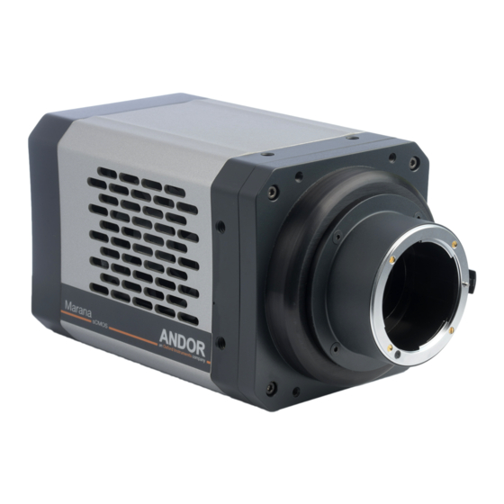
Sona & Marana SECTION 2: PRODUCT OVERVIEW This section provides an overview of the Sona and Marana. Please note that Sona configuration is shown below which will also cover the Marana model. Please refer to the additional information supplied for details of any model specific differences. -
Page 16: R Ear P Anel
Sona & Marana 2.2 R anel External I/O ON/OFF Power Input Connection Switch USB 3 Type-B port Water Connections: 4BV6 Compatible with tailpipes Sep 2019 CoaXPress port for 6 mm bore soft PVC hose (2 plcs) Figure 3: Rear Panel USB Connectivity USB 3 connection provides a robust high speed connection to the control PC. -
Page 17: P Ower R Equirements
Sona & Marana Ext Trigger (and Spare*)Inputs Camera 3.3V (5 V tolerant) > 2.4V Logic level 1 Input triggers on positive edge < 0.8V Logic level 0 10K Ohms Arm (Fire*, Fire n*) and AUX_OUT Outputs Camera > 2.0V > 1K Ohms 10K Ohms <... -
Page 18: Section 3: Installation
Sona & Marana SECTION 3: INSTALLATION WARNINGS: • PRIOR TO COMMENCING INSTALLATION, THE USER SHOULD REFER TO THE SAFETY AND WARNING INFORMATION AND UNPACKING INSTRUCTIONS AT THE BEGINNING OF THIS MANUAL. • DUE CARE MUST BE TAKEN WHEN LIFTING THE CAMERA. ENSURE THAT THE MOUNTING AND CONNECTED ASSEMBLY IS SECURE AND ABLE TO SUPPORT THE WEIGHT OF THE CAMERA. -
Page 19: Mount And Mount Daptors
Sona & Marana 3.2.2 f- MoUnt and MoUnt daptoRs Note: F-Mount and T-mounts- Use the inner set of mounting points (shown in section 3.2.1). Removing the F/T-mount 1. Place the camera on its side (to prevent debris and dust landing on the window). 2. -
Page 20: C Onnecting The C Amera To The Pc
Sona & Marana 3.4 c onnecting tHe aMeRa to tHe The camera connects to a PC via USB 3 this provides a standard, robust and high speed connection with the control PC. It is recommended to use the supplied USB 3 card as this will ensure consistent performance. Other USB ports on the PC may share bandwidth with other devices and peripheral components. -
Page 21: C Onnecting Via Usb
Sona & Marana 3.4.2 c onnecting tHe aMeRa to tHe 3.4.2.1 c onnecting via • Connect the USB cable from the camera to the appropriate PCIe card on the control PC. 4BV6 Sep 2019 3.4.2.2 c onnecting via Ress • Connect the 2 Lane CoaXPress cable from the camera to the CXP (PCIe) card on the control PC. -
Page 22: C Onnecting A C Ooling S Ystem
Sona & Marana 3.6 c onnecting a ooling ysteM The camera can use either air cooling to cool to 0 C or -25 C, or optional liquid cooling for deeper cooling to 3.6.1 i MpoRtant onsideRations WHen Using iqUid ooling ysteMs •... -
Page 23: C Oolant R Ecommendations
Sona & Marana Hose inserts are provided to enable connection to coolant hoses. • Coolant Hose Inserts: Two barbed coolant hose inserts (replacement part code ) are 6MM-HOSE-BARBS supplied as standard, suitable for connection to 6 mm [0.25”] internal diameter soft PVC tubing / hose. •... -
Page 24: C Onnecting The L Iquid C Ooling S Ystem
Sona & Marana 3.8 c onnecting tHe iqUid ooling ysteM An overview for connecting a liquid cooling system is outlined below- please refer to the information supplied with your cooling system for further information. 3.8.1 c onnecting tHe oolant oses 1. -
Page 25: 3.9 Installing Software And Drivers
Sona & Marana 3.9 INSTALLING SOFTWARE AND DRIVERS 3.9.1 M iniMUM oMpUteR eqUiReMents • 3.0 GHz single core or 2.4 GHz dual or quad core processor • 4 GB RAM • Hard drive: 850 MB/sec write speed recommended for the data rate associated with the max. frame rates. 100 MB free hard disc to install software •... -
Page 26: C Hecking & S Etting Bios Options ( For Pc S Not Supplied By A Ndor )
Sona & Marana 3.9.4 c & s bios Hecking etting options s not sUpplied by ndoR Enter the BIOS menu when starting PC. For Dell workstations, press F12 at start-up and select System Setup in the One Time Boot Menu. For Dell workstations 3 options in the Performance menu of the BIOS need to be checked/set: •... -
Page 27: Section 4: Operation
Sona & Marana SECTION 4: OPERATION WARNINGS: • IF THE EQUIPMENT IS USED IN A MANNER NOT SPECIFIED BY ANDOR OR ITS DISTRIBUTORS, THE PROTECTION PROVIDED BY THE EQUIPMENT MAY BE IMPAIRED. • PLEASE READ THE USER GUIDES SUPPLIED WITH YOUR SYSTEM COMPONENTS AND CAMERA CONTROL SOFTWARE PRIOR TO USE. -
Page 28: Xtended Ynamic Ange (Edr)
Sona & Marana Light (photons) hits the sensor and generates charge (electrons). The photo-generated charge is converted to an analog voltage for each pixel amplifier. These pixel voltages are transferred to the column bus via a row select signal. The analog voltages are then converted to digital signals via columns of analog to digital (A/D) converters. The final digitized signals are then read out sequentially at a pixel readout speed of up to 310 MHz. - Page 29 Sona & Marana Marana 4.2B-6 Frame Rates Spectroscopy Mode - Vertically binned tracks (overlap ON) Max Spectra Rate Array Size (W x H) 16-bit 12-bit (Low Noise) any x 1 25253 14881 any x 2 25253 14881 any x 8 15152 8929 any x 1200...
-
Page 30: Sing Roi (Aoi )
Sona & Marana Another consideration is data storage. High frame rate, full frame images at 16-bit can quickly generate many gigabytes worth of data. Using 12-bit, smaller ROIs or frames rates can help to reduce the amount of image data produced. 4.4.3 U (aoi sing... -
Page 31: B Lemish C Orrection F Ilter
Sona & Marana 4.4.6 b leMisH oRRection ilteR The Blemish Correction Filter identifies and compensates for three types of blemishes during the FPGA processing step: Hot Pixels Noisy Pixels Unresponsive Pixels sCMOS sensors are particularly susceptible to hot pixel blemishes. These are spurious noise pixels that have significantly higher darkcurrent than the average. -
Page 32: S Oftware A Cquisition E Vents
Sona & Marana 4.6 s oftWaRe cqUisition vents Software Acquisition Events are only accessible via SDK - these are not available in Solis, Fusion, iQ or other software but may be used internally. Refer to the SDK3 manual for further information on configuration of Software Acquisition Events. -
Page 33: R Olling S Hutter M Echanism
Sona & Marana camcorders were the image readout rate was not fast enough to keep up with a panned image. In modern sCMOS cameras however, the readout speeds are are faster and rolling shutter is suitable for the majority of scientific applications. -
Page 34: Iming Arameters And Xternal Riggering
Sona & Marana 4.7.3 t iMing aRaMeteRs and xteRnal RiggeRing The timing tables accompanying each of the triggering diagrams that follow indicate the exposure and cycle times achievable in each triggering mode. These are based on Frame and Row Periods as shown below. Timing Parameters based on Sensor Clock Speed: 1 Row 6.6 μs (16-bit) - Page 35 Sona & Marana Figure 8: Internal triggering “long” (non-overlap) Parameter Minimum Maximum Exposure 4 Rows 600 s Cycle Time (1/Frame Rate) Exposure + 1 Frame + 2 Rows Note: actual minimum Exposure time is 11.2 μs in 12-bit mode and 6.6 μs in 16-bit mode. The exposure time is incremented in 1 Row time steps.
-
Page 36: R Olling S Hutter I Nternal T Riggering (O Verlap M Ode )
Sona & Marana 4.7.5 R olling HUtteR nteRnal RiggeRing veRlap Internal Triggering in Overlap Mode allows the user to perform an exposure and acquire images from the sensor simultaneously. This is achieved by starting a new exposure for a new frame while the current frame’s exposure is being read out from the sensor. -
Page 37: R Olling S Hutter E Xternal / S Oftware T Riggering (N On -O Verlap M Ode )
Sona & Marana Parameter Minimum Maximum Exposure 4 Rows 600 s Short Exposure: 1 Frame + 2 Rows Cycle Time (1/Frame Rate) Long Exposure: Exposure + 2 Rows FIRE Any low period ~5.6 μs in 12-bit and ~9.8 μs in 16-bit (1 Row) 4.7.6 R olling HUtteR... - Page 38 Sona & Marana Figure 12: External Triggering “long” (non-overlap) Parameter Minimum Maximum Exposure 4 Rows 600 s Cycle Time (1/Frame Rate) Exposure + 1 Frame + 2 Rows External Start Delay 1 Rows 2 Rows EXT Trig Pulse Width 10 ns version 1.1 rev 04 Mar 2020...
-
Page 39: Olling Hutter Xternal Xposure Riggering On Verlap Ode )
Sona & Marana 4.7.7 R olling HUtteR xteRnal xposURe RiggeRing veRlap On detection of the trigger event a reset read out is initiated, this effectively begins a new exposure. When the external trigger input goes LOW, a signal frame read out phase begins. When the frame has been read out completely, the Arm goes high and the camera waits for the next trigger event to be detected. -
Page 40: R Olling S Hutter E Xternal E Xposure T Riggering (O Verlap M Ode )
Sona & Marana 4.7.8 R olling HUtteR xteRnal xposURe RiggeRing veRlap In overlap mode, every positive edge of an external trigger will trigger a frame read out and start a new exposure for the next frame. The period of external trigger pulse defines exposure and cycle time for each frame read out. On detection of the positive edge a frame read out is initiated at the start of the next Row read period. -
Page 41: Olling Hutter Xternal Tart Riggering
Sona & Marana 4.7.9 R olling HUtteR xteRnal taRt RiggeRing In this mode the camera will wait for a single external trigger event. Once this external trigger event is detected, the camera will progress as if the camera was in internal trigger mode (see Section 4.7.4 and 4.7.5). The ARM signal indicates to the user when the camera is ready to detect an External Start Trigger. -
Page 42: Section 5: Maintenance
Sona & Marana SECTION 5: MAINTENANCE THERE ARE NO USER-SERVICEABLE PARTS INSIDE THE CAMERA. DAMAGE CAUSED BY UNAUTHORISED MAINTENANCE OR PROCEDURES WILL INVALIDATE THE WARRANTY. 5.1 R egUlaR Hecks • The state of the product should be checked regularly, especially the integrity of the PSU and the mains cable. •... -
Page 43: T Ools R Equired
Sona & Marana 5.4.1 t ools eqUiRed • Compressed Air Can (or source of clean compressed air) • Optics Brush 5.4.2 W indoW leaning RocedURe Remove the camera from your microscope (or other optical equipment) and place it on a clean dry surface. Use the camera control software to open the shutter (if fitted). -
Page 44: Section 6: Troubleshooting
Sona & Marana SECTION 6: TROUBLESHOOTING 6.1 p Reventing ondensation Key Risks • Take special care during installation as the temperature of the camera may be low from shipping or storage. When moved to a warmer environment such as a lab, there is a higher risk of condensation forming. Therefore, ensure that sufficient time is allowed for the product to reach the ambient temperature of the operating environment before use (this may take several hours). -
Page 45: Q Uick T Roubleshooting G Uide
Sona & Marana 6.2 q Uick RoUblesHooting Uide Issue Possible Cause Action Camera buzzer does not sound on start-up. Communication error. Ensure that power is connected to the camera and the On/Off switch is set to On Camera is not recognized by PC. Camera not switched on. -
Page 46: Appendix A: Technical Specifications
Sona & Marana APPENDIX A: TECHNICAL SPECIFICATIONS Performance Specifications •1 Model Sona and Marana 4.2B-11 Sona 2.0B-11 Sona and Marana 4.2B-6 Sensor Type Back-Illuminated Scientific CMOS 2048 (W) x 2048 (H) 1400 (W) x 1400 (H) 2048 (W) x 2048 (H) Array Size 4.2 Megapixel 2.0 Megapixel... - Page 47 Sona & Marana General Specifications •1 Model Sona and Marana 4.2B-11 Sona 2.0B-11 Sona and Marana 4.2B-6 O: Fire Row 1, Fire Row n, Fire All, Fire Any, Arm I: External Trigger Modes Internal, External, External Start, External Exposure, Software Software Exposure Events Start exposure - End exposure (row 1), Start exposure - End exposure (row n) •5...
- Page 48 Sona & Marana External Power Supply Requirements Low Voltage Supply Input 15 V +/- 5% Low Voltage Supply Current Right-angle Plug: Fischer WSO 104 A037-130+ Low Voltage Supply Cable Connector Straight Plug: Fischer S 104 A037-130+ Required Cable Clamp Set: Fischer E3 104.3/6.7+B Pins 1 &...
-
Page 49: Appendix B: Mechanical Drawings
Sona & Marana APPENDIX B: MECHANICAL DRAWINGS Sona 4.2B-6 Marana 4.2B-6 175.4 6.906 166.8 6.565 36.5 1.437 15.2 0.598 CUSTOMER MOUNTING POINTS 0.75 0.030 17.5 0.75 0.691 0.030 8 X 1/4-20 UNC 8.0 0.313 (C-MOUNT FOCAL PLANE) (2 PER SIDE) Weight: approx. -
Page 50: Appendix C: Dewpoint Information
Sona & Marana APPENDIX C: DEWPOINT INFORMATION To avoid issues with condensation, the coolant temperature must be set above the dewpoint- the temperature at which condensation (dew) will form. In the relatively dry conditions of an air conditioned lab, or a cool dry climate, use of a coolant temperature of 10 C should not cause any problems. -
Page 51: Appendix D: Reference Information
Sona & Marana APPENDIX D: REFERENCE INFORMATION ltRa ecHnology UltraVac is Andors proprietary vacuum technology that provides a permanent, hermetically sealed enclosure (without O-rings) for the sensor. This ensures maximum cooling performance, with a reliability proven through years of use in Andor cameras such as the iXon EMCCD, iKon and Newton series- the Mean Time Between Failure (MTBF) value is >... -
Page 52: Appendix E: Other Information
Sona & Marana APPENDIX E: OTHER INFORMATION erms and ondiTions of ale and arranTy nformaTion The terms and conditions of sale, including warranty conditions, will have been made available during the ordering process. The current version may be viewed at: www.andor.com/pdfs/literature/Andor_Standard_Warranty.pdf 2006 (Weee) asTe...
Need help?
Do you have a question about the ANDOR Sona 4.2B-6 and is the answer not in the manual?
Questions and answers