
Related Manuals for Oxford Instruments ANDOR Kymera 328i Series


Summary of Contents for Oxford Instruments ANDOR Kymera 328i Series
- Page 1 The Kymera 328i Version 1.2 revised 22 July 2019 User Guide andor.com © Andor Technology 2019...
-
Page 2: Table Of Contents
Kymera 328i TABLE OF CONTENTS SECTION 1: INTRODUCTION ......................10 TECHNICAL SUPPORT ......................11 DISCLAIMER .......................... 12 COPYRIGHT AND PROTECTIVE NOTICES ................12 TRADEMARKS AND PATENT INFORMATION ............... 12 PACKING LIST ........................13 1.5.1 Optional Supplied Accessories ................14 ACCESSORIES FOR THE KYMERA 328I ................14 SECTION 2: PRODUCT OVERVIEW .................... - Page 3 Kymera 328i INSTALLATION OF ACCESSORY PARTS ................27 3.4.1 Grating Turret Replacement and xPressID ............28 3.4.2 Installing a Filter Wheel .................... 30 3.4.3 Accessing the Filters ....................30 3.4.3.1 Accessing and Changing the Filters ............31 3.4.3.2 Initializing the Filter Wheel ..............32 3.4.3.3 Filter Wheel Control and Updating the Filter Details in the Spectrograph Memory ................
- Page 4 Kymera 328i 4.10 DISPERSION OPTIMISER ...................... 51 4.10.1 Steps to use the Dispersion Optimiser ..............52 SECTION 5: MAINTENANCE ......................55 REGULAR CHECKS ....................... 55 ANNUAL ELECTRICAL SAFETY CHECKS ................55 FUSE REPLACEMENT ......................55 CLEANING (EXTERNAL) ......................55 GRATING ADJUSTMENT ....................... 56 5.5.1 Warning Information if Lid is Removed ..............
- Page 5 Kymera 328i evision istoRy Version Released Description 23 Oct 2017 Initial release. 29 May 2019 Updated USA and Asia-Pacific addresses (page 11) and technical drawings (page 62) 22 July 2019 Updated reference on page 34, updated table in section 3.4.6 Version 1.2 rev 22 July 2019...
- Page 6 Kymera 328i afety and aRning nfoRmation PLEASE READ THIS INFORMATION FIRST CAUTION – USE OF CONTROLS OR ADJUSTMENTS OR PERFORMANCE OF PROCEDURES OTHER THAN THOSE SPECIFIED HEREIN MAY RESULT IN HAZARDOUS RADIATION EXPOSURE. If the equipment is used in a manner not specified by Andor, the protection provided by the equipment may be impaired.
- Page 7 Kymera 328i 18. Optical surfaces are delicate and should never be touched. To avoid accidental damage, and to minimise dust settling on the optical surfaces, always keep the turret lid on and avoid exposure to a dusty environment. 19. Use gloves to remove grating turret and further minimize the risk of damage to the gratings. Store unused grating turrets in a dust-free environment, ideally a desiccator.
- Page 8 Kymera 328i afety ymbols The following are explanations of the safety symbols found on this product: Caution, potential hazard, refer to manual for information. Caution, risk of electric shock. Caution, hot surface. Risk of burns- shutter assembly gets hot in operation. Ensure shutter assembly is allowed to cool if the lid is removed for the maintenance procedures described in this manual.
- Page 9 Kymera 328i & s Hipping toRage Recautions Unpacking and Inspection: • Carefully unpack the unit and retain packaging to return equipment for servicing as shown in the following section. • If the equipment appears damaged in any way, return it to sales outlet in its original packaging. No responsibility for damage arising from the use of non-approved packaging will be accepted.
-
Page 10: Section 1: Introduction
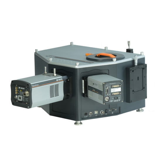
Kymera 328i SECTION 1: INTRODUCTION Thank you for choosing an Andor Kymera 328i spectrograph. Please read this user guide before using your spectrograph. Figure 1: Andor Kymera 328i spectrograph shown with Andor Newton CCD and Zyla sCMOS cameras attached. Version 1.2 rev 22 July 2019... -
Page 11: Technical Support
Kymera 328i 1.1 t ecHnical uppoRt If you have any questions regarding the use of this equipment, please contact the representative* from whom your system was purchased, or: Europe Andor Technology Andor Technology 7 Millennium Way 300 Baker Avenue Springvale Business Park Suite # 150 Belfast Concord... -
Page 12: Disclaimer
Andor, eXpressID and the Andor logo are trademarks of Andor Technology. Andor Technology is an Oxford Instruments company. All other marks are property of their owners. Changes are periodically made to the product and these will be incorporated into new editions of the manual. New releases of the manual are available through MyAndor: http://my.andor.com/login.aspx. -
Page 13: Packing List
Kymera 328i 1.5 p acking After having removed the spectrograph from its packaging, confirm that the following standard items are included: Item Quantity Kymera 328i Spectrograph Description Quantity Description Quantity System Power Supply performance Unit (PSU) booklet Power Cable Hex key set (3 m, country (2 mm, 3 mm &... -
Page 14: Optional Supplied Accessories
Kymera 328i 1.5.1 o ptional upplied ccessoRies Depending on the options purchased, the following optional accessories may also be included: • Additional grating turrets • Light-coupling interfaces: Accessories such as shutter, filter wheel & motorized slits may already have been installed on the spectrograph, prior to shipping •... -
Page 15: Section 2: Product Overview
Kymera 328i SECTION 2: PRODUCT OVERVIEW The Kymera 328i is a research-grade high performance spectrograph, yet it is compact and easy to use. It has been designed to work with demanding low-light applications, but is equally suited to routine measurements. The Kymera 328i is the latest addition to the Kymera series of spectrographs and is compatible with a wide range of Andor and other detectors. -
Page 16: Signal And Power Connections
Kymera 328i 2.2 s ignal and oWeR onnections Signal and power connections are grouped together on the front panel as shown below: Connection Panel of the Kymera 328i Accessory Connector (e.g. filter wheel) Power Shutter Power Input (BNC) Switch Figure 3: Signal and Power connections Power input (24V) Power input connection (24 V DC, 3 A max) from the external power supply unit. -
Page 17: Power Supply
Kymera 328i 2.3 p oWeR upply The Kymera 328i is powered by external PSU- details are shown in the table below. Parameter Mains Power Supply 100 - 240 V AC, 47 - 63 Hz Requirements PSU Output 24 V DC, 5A NOTES: The electrical mains lead must be certified for use in your country, and where regulations demand must be fitted with a 5 Amp 250 VAC rated fuse. -
Page 18: Section 3: Installation
Kymera 328i SECTION 3: INSTALLATION Please read before installation: • The spectrograph is intended for installation with the 4 feet sitting on a horizontal, flat surface. • It is intended for lab use only and should not be subject to dynamic loads or vibrations in excess of 1g. •... -
Page 19: An Overview For Getting Started With Your Kymera 328I Spectrograph
Kymera 328i 3.1 a n oveRvieW foR getting staRted WitH youR ymeRa i spectRogRapH After removing the spectrograph from the box and checking all components are correct as shown in the preface of this manual, and as ordered, carry out the following actions as described in this Section to complete set-up of your spectrograph. -
Page 20: Installing The Solis/Sdk Software
Kymera 328i 3.1.1 i /sdk s nstalling tHe olis oftWaRe Terminate and exit any programs which are running on the PC. Insert the Andor software CD. The InstallShield Wizard now starts. If it does not start automatically, run the file setup.exe directly from the CD then follow the on-screen prompts that then appear (Software screens may differ slightly from those shown, depending on your Operating system and software version). -
Page 21: Software And Driver Installation
Kymera 328i 3.1.2 s oftWaRe and RiveR nstallation When Andor Solis software is installed, the drivers for the Kymera and Shamrock USB should be in the Shamrock USB Drivers folder highlighted below: NOTE: If the drivers are not present, copy the USB Drivers folder from the installation CD-ROM to the Andor Solis folder. -
Page 22: Attaching A Camera To A Kymera Or Shamrock Spectrograph
Kymera 328i 3.2 a ttacHing a ameRa to a ymeRa oR HamRock spectRogRapH If the spectrograph is not supplied with a camera/detector attached, refer to the guidelines below and also the user or installation guide(s) provided with your camera/detector for mounting flange instructions. Remove the blanking plate(s) from the required output port(s) of the spectrograph using a (+) type screwdriver. -
Page 23: Connecting The Camera To The Spectrograph Via Usb
Kymera 328i Note: there is no external mechanical focus adjustment required for the Kymera 328i. The focus is automatically adjusted through the motorized, intelligent active focus interface. The auto-offset adjustment function also allows for easy adjustment of the detector offset. 3.2.1 c onnecting tHe ameRa to tHe... -
Page 24: Disconnecting The Usb Interface
Kymera 328i 3.2.2 d usb i isconnecting tHe nteRface If the USB cable needs to be disconnected please follow the steps shown below. This is the same procedure you should be familiar with from using other USB devices with your PC. Scroll over the USB icon at the bottom-right of the screen, and the Safely Remove Hardware indication appears. -
Page 25: Adjusting The Level And Height Of The Spectrograph
Kymera 328i 3.2.4 a djusting tHe evel and eigHt of tHe pectRogRapH The Kymera 328i has 4 adjustable feet to enable the level and height to be adjusted as required to match the other parts of the system, e.g. a microscope. Figure 5: Use the standard adjustable feet and optional spacer kit to match optical height with a microscope. -
Page 26: Standalone Spectrograph
Kymera 328i 3.2.5 s tandalone pectRogRapH Where a “standalone” spectrograph (i.e. without an Andor camera) has been purchased, the unit is supplied with an appropriate camera flange to allow a camera to be attached to the spectrograph body. The camera must be attached to the flange and the flange attached to the spectrograph body with the screws supplied. -
Page 27: Installation Of Accessory Parts
Kymera 328i 3.4 i nstallation of ccessoRy aRts This section outlines the procedures for installation or replacement of optional accessories. The Kymera spectrograph series has been designed so that installation and exchanging of accessories is as easy as possible. • Grating Turret (Section 3.4.1) •... -
Page 28: Grating Turret Replacement And Xpressid Tm
Kymera 328i 3.4.1 g Rating uRRet eplacement and x Ress Grating turrets can easily be interchanged by end-users. Settings for up to 3 turrets can be stored. Each turret comes with xPressID , a pre-programmed RFID (Radio-frequency identification) chip which means there is no need to re-run calibration if a grating turret has been used and configured previously. - Page 29 Kymera 328i Store the turret in a safe place (e.g. desiccator) to protect it from damage and debris. Lifting the replacement turret by the handle, carefully lower it into the turret cavity, align the alignment arrow on the turret and panel. Tighten the turret locking knob. Refer to the warning at the start of this section. Ensure the Turret is aligned correctly with the alignment arrow Replace the turret lid and slide the lid lock to the locked position to secure it.
-
Page 30: Installing A Filter Wheel
Kymera 328i 3.4.2 i nstalling a ilteR Heel The following section outlines how to install a filter wheel (shown for a Kymera 193i). Turn off power and disconnect the Spectrograph from the power supply. Remove any spacer and accessories attached to the input port e.g. Slit Mechanism as shown in this example. Line-up the filter wheel with the 4 mounting holes on the spectrograph wall, as highlighted on the figure below. -
Page 31: Accessing And Changing The Filters
Kymera 328i 3.4.3.1 a ccessing and Hanging tHe ilteRs Unscrew the filter wheel access cover. With the spectrograph powered on, check the filter position ID number shown in the software. NOTES: The filter position accessible via the access hole has an ID number 3 less than the filter position in the optical path. -
Page 32: Initializing The Filter Wheel
Kymera 328i 3.4.3.2 i nitializing tHe ilteR Heel After fitting, or replacing filters, it is good practice to synchronise the filter wheel hardware with the software interface. To reset the filter wheel, press the reset button on the filter wheel control graphic: Filter Wheel Reset Button 3.4.3.3 f... -
Page 33: Shutter
Kymera 328i 3.4.4 s HutteR Remove any slit mechanisms, spacers and filter wheels as described in the preceding sections, to access the shutter. This operation can be facilitated as follows: 1. Turn off power to the spectrograph. WARNING: SHUTTER ASSEMBLY GETS HOT DURING OPERATION- ENSURE UNIT IS ALLOWED TO COOL TO PREVENT RISK OF BURNS. -
Page 34: Manual, Motorized And Wide Aperture Slits
Kymera 328i 3.4.5 m anual otoRized and peRtuRe lits A range of slits are available (refer to specifications sheet). The slit assembly is easily installed used the supplied screws. WARNING: The wide aperture slit (SR-ASZ-0086/85) has two precision blades that are adjusted by a plunger mechanism to set the aperture. -
Page 35: Section 4: Operation
Kymera 328i SECTION 4: OPERATION The spectrograph is controlled via the Dashboard control. This easy-to-use graphical user interface allows you to control the main hardware components of the spectrograph as well as several acquisition parameters. This can be seen in figure 10. Figure 10: Andor Solis for Spectroscopy Dashboard Interface When the dashboard is launched it displays only the panel and graphic for the accessories that have been installed (for example, Shutter, Filter, Flipper, Grating and Output Slit). -
Page 36: Detector Controls
Kymera 328i 4.2 d etectoR ontRols The following sections describe the basic camera controls incorporated on the Dashboard control panel. For more detailed descriptions of these parameters and other available adjustments please refer to the supplied Solis and camera manuals. 4.2.1 e xposuRe ontRol... -
Page 37: Spectrograph Controls
Kymera 328i Multi-track: Multi track modes are associated with 2-D data display and allow you to define multiple tracks on the CCD with two options available, i.e. Standard & Custom. When one option is selected, the parameters for the other option are disabled Setup: adjust configuration options for the selected mode. -
Page 38: Changing The Wavelength Range
Kymera 328i 4.3.2.1 c Hanging tHe avelengtH ange The start, centre and end wavelengths can be changed in one of two ways: Drag the wavelength slider with the mouse. Position the cursor within the slider (cursor changes to pointing hand), click the LEFT mouse button and drag the slider to the required centre wavelength. Place the cursor at either side of the slider to move it towards the cursor (LEFT mouse button for coarse nudges and the RIGHT mouse button for fine nudges). -
Page 39: Step 'And' Glue
Kymera 328i 4.3.3 s ‘ ’ g The Step and Glue function allows the user to build up a composite spectrum made up of individual slightly overlapping spectra , and therefore gives access to larger spectrum bandpass while maintaining high spectral resolution. The user selects the start and wavelength of the scan region and the grating to be used. - Page 40 Kymera 328i It will be noticed that the Step and Glue slide bar control will expand or contract in length to indicate the number of scans that the system must perform to acquire this data (see below). Note that the acquire spectra overlap slightly. This allows the Step and Glue algorithm to glue the spectra together.
-
Page 41: Relative Efficiency Correction
Kymera 328i 4.3.3.1 R elative fficiency oRRection A Relative Efficiency Correction (REC) is possible in Step and Glue mode of your Andor spectrograph. This enables the quantitative measurement of peak intensity ratios, and to correct artefacts such as etaloning. Setting up REC First ensure you are in “Single Scan”... -
Page 42: Grating Turret Control
Kymera 328i 4.4 g Rating uRRet ontRol The Grating Turret Control is used to select a new grating by rotating the grating turret to a new position. There are two turret positions available so that a maximum of two grating can be fitted at any one time. If additional gratings are needed then an additional turret with alternative gratings can be easily swapped in by the user. -
Page 43: Offset Adjustment Panel
Kymera 328i 4.5 o ffset djustment anel The Offset Adjustment function allows the user to adjust the calibration of the instrument. Once these are set they will be automatically selected by the software. We shall define two types of offset. A detector offset and a grating offset. The Detector offset value can be adjusted to correct for any mechanical change that shifts (offsets) the displayed spectrum from the expected calibrated position. -
Page 44: Focus Mirror
Kymera 328i 4.5.1 f ocus iRRoR The focus mirror function allows the accurate, and reproducible adjustment of the focus of a spectral feature, onto the detector at the press of a button. The user may chose to manually adjust the focus, or simply to use ‘Auto Focus’. Optimal focus positions are captured automatically in the spectrograph EEPROM for each grating on a grating turret and each spectrograph output port. - Page 45 Kymera 328i If the spectral line is positioned on the centre line, then an adjustment to the detector offset value is not required. If there is a discrepancy between the displayed centre wavelength and the actual wavelength position of the spectral line, the offset should be adjusted. Press the appropriate + or - offset adjustment buttons to bring the centre of the spectral line onto the red centre line.
-
Page 46: Slit Drive Control
Kymera 328i 4.6 s Rive ontRol The Slit Drive Control is used to control the Motorised Slit Assemblies. The slits are used to control the amount of incident light that enters the spectrograph. The width can be varied between 10 μm and 2500 μm (in steps of 2.5 μm). The slit height may be altered by interchanging optional baffle plates (attached to the slit assembly using 5x M2 cross- head screws). -
Page 47: Filter Wheel Control
Kymera 328i 4.7 f ilteR Heel ontRol The optional filter wheel accessory is controlled through the Filter Wheel Control. The Filter Wheel Control indicates the currently selected filter and provides details of the filter at the bottom of the control. The filter positions and their details are stored in non-volatile memory (EEPROM) in the instrument and should be input by the user on first use of the system). -
Page 48: Shutter Control
Kymera 328i 4.8 s HutteR ontRol If you have a shutter (side or direct) attached to your system the Shutter Control can be used to set the shutter mode of operation. There are six modes of operation available: Always Open: The shutter will be open before, during, and after any data acquisition. Always Closed: This option is selected if you wish to take a series of acquisitions in darkness and do not require the shutter to open between acquisitions. -
Page 49: Shutter Operation Management
Kymera 328i 4.8.1 s HutteR peRation anagement <10 Hz 10 Hz-40 Hz >40 Hz Shutter operates for 4 seconds, then Shutter operates continuously Shutter will not operate past 40 Hz stops and beeps for 60 seconds All frequencies are approximate due to tolerances in the PIC oscillator. Shutter operation complies with manufacturer requirements. -
Page 50: Flipper Mirror Control
Kymera 328i 4.9 f lippeR iRRoR ontRol The Flipper Mirror Control allows you to rapidly select the required input or exit port(s). Port 1, or Port 2, is selected by simply clicking on the appropriate port on the Flipper Mirror Control dialog. The selected port is highlighted in yellow. Version 1.2 rev 22 July 2019... -
Page 51: Dispersion Optimiser
Kymera 328i 4.10 d ispeRsion ptimiseR In the unlikely event that the spectrograph calibration (dispersion) is not correct, the user can re-calibrate the system with the Dispersion Optimiser function. Using more than 1 wavelength on each grating will ensure that the new values calculated are optimised for the useful wavelength ranges on all gratings used. -
Page 52: Steps To Use The Dispersion Optimiser
Kymera 328i 4.10.1 teps to use tHe ispeRsion ptimiseR Note: Ensure that your spectrograph is calibrated correctly before performing this procedure. Choose a Grating and Wavelength and Add them to the list • Choose 1 grating, or the All Gratings Option: •... - Page 53 Kymera 328i Click the Optimise button • If you have Peak Checking enabled, the following dialog will pop up at each of your chosen wavelength points to confirm the correct peak is being displayed: • Two red lines will be drawn around the centre range being used and the user should confirm that the peak they are expecting is within this range.
- Page 54 Kymera 328i • By adjusting the grating offset the user can move the peak and try to move it in range. • The user can select Cancel at any time and this will abort the current optimization procedure. • During the acquisition the user can choose to Abort and the operation will terminate at the earliest opportunity. Choose Save to EEPROM (or not save) the values to the spectrograph EEPROM.
-
Page 55: Section 5: Maintenance
Kymera 328i SECTION 5: MAINTENANCE THERE ARE NO USER-SERVICEABLE PARTS INSIDE THE SPECTROGRAPH. A NUMBER OF SCREWS ON THE PRODUCT HAVE BEEN MARKED WITH RED PAINT TO PREVENT TAMPERING. IF YOU ADJUST THESE SCREWS, YOUR WARRANTY WILL BE VOID. IF SERVICE IS REQUIRED PLEASE CONTACT YOUR ANDOR REPRESENTATIVE. NOTE: THE LID SHOULD ONLY BE OPENED WHEN ABSOLUTELY NECESSARY TO PREVENT INGRESS OF DUST INTO THE UNIT. -
Page 56: Grating Adjustment
Kymera 328i 5.5 g Rating djustment Grating fine adjustment should not be required during normal use. However, it may be necessary after your spectrograph has been shipped, or otherwise moved. Whilst every effort is made to limit the shifting of optical components during shipment, it is possible that some misalignment may occur. -
Page 57: Warning Information If Lid Is Removed
Kymera 328i 5.5.1 W aRning nfoRmation if id is emoved The lid of the spectrograph forms part of the protective enclosure and should only be removed to perform the adjustment procedures as outlined in this manual. If may be removed by unscrewing the 7 thumbscrews. Optical parts are easily contaminated by dust, or easily damaged. - Page 58 Kymera 328i Each grating has two pairs of adjustment screws for Roll (screws 1 and 3), and for Tilt (screws 2 and 4). Each pair of screws work in opposition to each other, therefore for adjustment one should be loosened, then the other tightened. When you are happy with the grating position they should be gently tightened against each other and the final position re-confirmed.
-
Page 59: Electrical Connections For Accessories
Kymera 328i 5.6 e lectRical onnections foR ccessoRies When fitting motorized slit accessories, the user needs to access the spectrograph electronics board to plug in the devices. WARNINGS: Risk of damage to the system. Power to the system must first be turned off to carry out this operation. •... -
Page 60: Section 6: Troubleshooting
Kymera 328i SECTION 6: TROUBLESHOOTING Unit does not switch on • Check AC mains power lead is correctly plugged in to the building AC mains supply outlet, and that the DC output from the power supply unit is fully plugged into the Spectrograph. •... -
Page 61: Section 7: Specifications
Kymera 328i SECTION 7: SPECIFICATIONS 7.1 electRical and enviRonmental Parameter 100 - 240V, AC 47-63 Hz Power supply ratings Power consumption: 21W max, (with 10 Hz shutter and grating turret operation) Fuse rating 5A/250V Electrical safety EN 61010 Communication USB 2.0 Location to be used Indoor use only Altitude... -
Page 62: Appendix A: Mechanical Drawings
Kymera 328i APPENDIX A: MECHANICAL DRAWINGS Optical Axis Standard configuration shown with manual slit on input, CCD flange on straight output. Standard feet: Nominal optical axis height: 142.6 - 148.6 mm, Weight: 18 kg [ 39.7 lbs approx] increments of 6 mm with stackable spacer kit (SR-ASM-0098). Version 1.2 rev 22 July 2019... -
Page 63: Appendix B: Other Information
Kymera 328i APPENDIX B: OTHER INFORMATION erms and ondiTions of ale and arranTy nformaTion The terms and conditions of sale, including warranty conditions, will have been made available during the ordering process. The current version may be viewed at: http://www.andor.com/pdfs/literature/Andor_Standard_Warranty.pdf 2006 (Weee) asTe leCTroniC and...
Need help?
Do you have a question about the ANDOR Kymera 328i Series and is the answer not in the manual?
Questions and answers