
Related Manuals for Oxford Instruments ANDOR Shamrock 303i


Summary of Contents for Oxford Instruments ANDOR Shamrock 303i
- Page 1 Shamrock 303i Version 4.2 revised 15 October 2024 User Guide Covers Shamrock model: 303i andor.com © Andor Technology Ltd. 2016...
-
Page 2: Table Of Contents
Shamrock 303i TABLE OF CONTENTS ECTION 1: INTRODUCTION ......................10 TECHNICAL SUPPORT ......................11 DISCLAIMER ......................... 12 COPYRIGHT AND PROTECTIVE NOTICES ................12 TRADEMARKS AND PATENT INFORMATION ............... 12 PACKING LIST ........................13 1.5.1 Optional Accessories ....................14 ACCESSORIES FOR THE SHAMROCK SERIES ..............14 SECTION 2: PRODUCT OVERVIEW .................... - Page 3 Shamrock 303i INSTALLATION OF FILTERS (IF APPLICABLE) ..............26 3.3.1 Filter Access ......................26 3.3.2 Initializing the Filter Wheel..................27 3.3.3 Filter Wheel Control and Updating the Filter Details Stored in the ......Spectrograph Memory ....................27 GRATING TURRET REPLACEMENT ..................28 INSTALLATION OF ACCESSORY PARTS ................
- Page 4 Shamrock 303i FLIPPER MIRROR CONTROL....................48 4.10 DISPERSION OPTIMISER ...................... 49 4.10.1 Steps to use the Dispersion Optimiser: ..............50 SECTION 5: MAINTENANCE ......................53 REGULAR CHECKS ....................... 53 ANNUAL ELECTRICAL SAFETY CHECKS ................53 FUSE REPLACEMENT ......................53 CLEANING (EXTERNAL) ......................53 SECTION 6: TROUBLESHOOTING ....................
-
Page 5: Revision History
Shamrock 303i Revision History Version Released Description 11 Oct 2016 Content prepared from, and replacing previous Shamrock 303i User Guide Version 3.0 Aug 2008. Updated content in line with the machinery directive 2006/42/EC (all Sections) Presentation and manual structure updated to current company format (All sections) Revision History added Added link to Customer Support page on Website (Sections 1.1 and 5) -
Page 6: Safety And Warning Information
Shamrock 303i Safety and Warning Information PLEASE READ THIS INFORMATION FIRST If the equipment is used in a manner not specified by Andor, the protection provided by the equipment may be impaired. CAUTION – USE OF CONTROLS OR ADJUSTMENTS OR PERFORMANCE OF PROCEDURES OTHER THAN THOSE SPECIFIED HEREIN MAY RESULT IN HAZARDOUS RADIATION EXPOSURE. - Page 7 Shamrock 303i 18. Please note that this product is not designed to provide protection from ionising radiation. Any customer using this product in such an application should provide their own protection. 19. Your product is a precision scientific instrument containing fragile components. Always handle it with care. 20.
-
Page 8: Safety Symbols
Shamrock 303i afety ymbolS The following are explanations of the safety symbols found on this product: Caution, potential hazard Caution Sharp Caution, risk of electric shock Regulatory Information • The Shamrock spectrograph series complies with the requirements of the EU Electromagnetic Compatibility and Low Voltage Directives, specifically by satisfying the requirements of EN61326-1 and EN61010-1. - Page 9 Shamrock 303i Unpacking the Shamrock and Manual Handling IMPORTANT PRECAUTIONARY NOTICE: Correct manual handling techniques are important when installing Shamrock spectrographs so the integrity of the products is maintained and individuals involved are not exposed to unnecessary risks or possible injury, whilst performing any of the following actions: •...
-
Page 10: Section 1: Introduction
Shamrock 303i SECTION 1: INTRODUCTION Thank you for choosing an Andor Shamrock spectrograph. Please read this manual and information supplied with any other system components and software before using your Shamrock spectrograph. This manual covers the following models: Shamrock 303i The Shamrock 303i is available in two configurations: As a pre-aligned detector/spectrometer system allowing fast and efficient set-up, or, As a stand-alone spectrograph, to retrofit to existing cameras/systems... -
Page 11: Technical Support
Shamrock 303i 1.1 t echnical upport If you have any questions regarding the use of this equipment, please contact the representative* from whom your system was purchased, or: Europe Andor Technology Ltd. Andor Technology 7 Millennium Way 425 Sullivan Avenue Springvale Business Park Suite # 3 Belfast... -
Page 12: Disclaimer
Andor and the Andor logo are trademarks of Andor Technology Ltd. Andor Technology is an Oxford Instruments company. All other marks are property of their owners. Changes are periodically made to the product and these will be incorporated into new editions of the manual. New releases of the manual are available through MyAndor. -
Page 13: 1.5 Packing List
Shamrock 303i 1.5 packing liSt After having removed the spectrograph from its packaging, confirm that the following standard items are included: Item Quantity Shamrock Spectrograph Model 303i Description Quantity Description Quantity System Power Supply performance Unit (PSU) booklet Power Cable Allen key set (3 m) Certificate of... -
Page 14: Optional Accessories
Shamrock 303i 1.5.1 o ptional cceSSorieS Depending on the Shamrock model and options purchased, the following optional accessories may also be included: • Detector flange(s) for output port(s). • Grating turret(s): The main grating turret may already be installed in the spectrograph. •... -
Page 15: Section 2: Product Overview
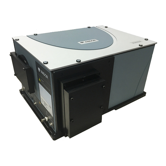
Shamrock 303i SECTION 2: PRODUCT OVERVIEW The Shamrock 303i imaging spectrograph is a research-grade, high performance, flexible and rugged platform designed for use in demanding low-light applications, but equally suited to routine measurements. Shamrock spectrographs are compatible with a wide range of Andor detectors, as well as those from other manufacturers. This section provides an overview of the main external features and the signal and power connections. -
Page 16: Signal And Power Connections
Shamrock 303i 2.2 S ignal and ower onnectionS 2.2.1 f ront anel The connections on the front panel of the Shamrock 303i are shown below: Power Input Camera Camera Gas Purge Shutter Accessory (USB) Port (6 pin) Figure 2: Front Panel Connections Power Input (24V DC) Power input connection (3-pin) from the external power supply unit. -
Page 17: Gas Purge Port
Shamrock 303i IMPORTANT NOTE: The output voltages are intended for attachment of Andor designed accessories. Other devices should only be connected with caution. Maximum current values are 24V@200mA, 12V@100mA and 5V@100mA. Failure to observe these limits may damage the system. For information on voltage selection using the jumpers, please contact your local Andor representative for further information. -
Page 18: Section 3: Installation
Shamrock 303i SECTION 3: INSTALLATION 3.1 a verview for etting up your hamrock pectrograph After you have removed the spectrograph from the box and checked all components against the packing list and they are as ordered, please follow the instruction below to prepare your spectrograph for use. An overview of the main steps is shown below: Installing the software (Solis for Spectroscopy or SDK). -
Page 19: Installing The Software (Solis Spectroscopy/Sdk)
Shamrock 303i 3.1.1 i /Sdk) nStalling the oftware oliS pectroScopy These guidelines provide a general overview; please refer to the software installation information supplied with your software. Terminate and exit any programmes which are running on the PC. Insert the Andor CD. The InstallShield Wizard should now start. If it does not start automatically, run the file setup.exe directly from the CD and follow the on-screen prompts that will guide you through the install process. -
Page 20: Software And Driver Installation
Shamrock 303i 3.1.2 S oftware and river nStallation When the Andor Solis software is installed, the drivers for the Shamrock should be found in the Shamrock USB Drivers folder. This is shown in the example below: NOTE: If the drivers are not present, copy the Shamrock USB drivers folder from the installation CD-ROM to the Andor Solis folder. -
Page 21: Connecting The Shamrock To The Power Supply And Pc
Shamrock 303i 3.1.3 c onnecting the hamrock to the ower upply and Ensure that the power to the spectrograph PSU is turned off. Connect the power cable to the power supply input of the spectrograph. Connect the USB cable between the USB input of the spectrograph and an available USB connection on the Plug in the power supply to the mains, but do not switch the power on. -
Page 22: Attaching A Camera To The Shamrock
Shamrock 303i 3.2 a ttaching a amera to the hamrock If the spectrograph is not supplied with a camera/detector pre-attached, refer to the guidelines below and also the user or installation guide(s) provided with your camera/detector. Remove the blanking plate from the spectrograph (4x M3 cap head screws, using a M2.5 allen key). Hold the camera horizontally, locate it on the flange and replace the screws- do not tighten fully. -
Page 23: Camera Signal And Power Connections
Shamrock 303i 3.2.1 c amera ignal and ower onnectionS The following instructions provide a simple overview of the connections required. Camera and power connections will vary with your specific model of camera- refer to your camera user manual for additional information. For Connection by USB Connect the USB cable between the USB connection on the Shamrock and a free USB socket on the PC. -
Page 24: Standalone Spectrograph
Shamrock 303i 3.2.2 S tandalone pectrograph Where a “standalone” spectrograph (i.e. without an Andor camera) has been purchased, the unit is supplied with an appropriate camera flange to allow a camera to be attached to the spectrograph body. The camera must be attached to the flange and the flange attached to the spectrograph body with the screws supplied. -
Page 25: Pre-Aligned Camera And Spectrograph
Shamrock 303i 3.2.3 p aligned amera and pectrograph When a pre-aligned camera and spectrograph package has been purchased the camera comes pre-fitted with a flange. This flange accurately locates the camera and flange assembly to the spectrograph body via precision pins and matching bushings (see figure below). -
Page 26: Installation Of Filters (If Applicable)
Shamrock 303i 3.3 i nStallation of ilterS if applicable Filters may be added, removed or replaced in the filter wheel via the filter access hole on the front face of the filter wheel housing. If this is necessary, please refer to the following procedures: 3.3.1 f ilter cceSS... -
Page 27: Initializing The Filter Wheel
Shamrock 303i 3.3.2 i nitializing the ilter heel After fitting, or replacing filters, it is good practice to synchronise the filter wheel hardware with the software interface. To re-initialise the filter wheel, press the reset button on the filter wheel control graphic. 3.3.3 f ilter heel... -
Page 28: Grating Turret Replacement
Shamrock 303i 3.4 g rating urret eplacement The grating turret contained within the Shamrock spectrographs can be easily replaced by end-users. The procedure for replacing the Grating turret is outlined below: WARNINGS: • ENSURE THE SPECTROGRAPH IS SWITCHED OFF BEFORE REMOVING THE LID •... -
Page 29: Installation Of Accessory Parts
Shamrock 303i Ensure the turret is correctly in position then carefully tighten the top screw. When you are satisfied that the grating turret is installed correctly, replace the lid. Navigate to the EEPROM settings (Hardware/Setup Spectrograph). 10. Click on the “System Configuration” and select the new turret. 11. -
Page 30: Grating Adjustment
Shamrock 303i 3.5.1 g rating djuStment Grating fine adjustment may become necessary after your Shamrock has been shipped, or otherwise moved. Whilst every effort is made to limit the shifting of optical components during shipment, it is possible that some misalignment may occur. -
Page 31: Correcting For Roll And Tilt
Shamrock 303i 3.5.1.2 c orrecting for oll and Screws are used for Roll and Tilt correction adjustment as shown below: There are two pairs of adjustment screws for Roll, and for Tilt (shown above). Each pair of screws work in opposition to each other, therefore for adjustment one should be loosened, then the other tightened. -
Page 32: Section 4: Operation
Shamrock 303i SECTION 4: OPERATION The Shamrock is controlled via the Dashboard control. This easy-to-use graphical user interface allows you to control the main hardware components of the Shamrock as well as several acquisition parameters. This can be seen in the figure below. -
Page 33: Emergency Mains Disconnection
Shamrock 303i 4.1 e mergency ainS iSconnection In case of emergency, the disconnecting point of the equipment is the mains power cord connected to the external power supply, or the mains socket switch: FOR EMERGENCY MAINS DISCONNECTION, SWITCH OFF THE POWER AT THE MAINS SOCKET AND REMOVE THE MAINS LEAD FROM THE EXTERNAL POWER SUPPLY. -
Page 34: Read Mode Control
Shamrock 303i 4.2.2 r ontrol The Read Mode Control dialog box can be used to change the way in which the information from the CCD in the camera is read. The mode is selected by clicking one of the buttons in the dialog box. Moving the cursor over each button displays a pop-up, indicating the mode selected by clicking on the button. -
Page 35: Spectrograph Controls
Shamrock 303i 4.3 S pectrograph ontrolS 4.3.1 r eSet ptionS When the Reset button on the Reset Menu is clicked, you then have several options that allow you to reset the various mechanisms in the system. This may be found to be necessary if a mechanism setting appears to have deviated from the displayed value (e.g. -
Page 36: Wavelength Drive Control
Shamrock 303i 4.3.2 w avelength rive ontrol The wavelength drive hardware sets the system to the target wavelength and also allows control of the grating selection. The wavelength range covered by the camera is calculated and displayed in the Wavelength section of the Dashboard. It is calculated by the software and accurately displayed in the visual control section of the dashboard. -
Page 37: Step And Glue
Shamrock 303i 4.3.3 S tep and The step and glue function allows to user to build up a composite spectrum made up of individual spectra. The user selects the start and end wavelengths of the scan region and the grating to be used. The software will then control the acquisition of several spectra that cover this spectral region. - Page 38 Shamrock 303i It will be noticed that the Step and Glue slide bar control will expand or contract in length to indicate the number of scans that the system must perform to acquire this data (see below). Note that the acquire spectra overlap slightly. This allows the Step and Glue algorithm to glue the spectra together.
- Page 39 Shamrock 303i An Hg/Ne spectrum acquired with a 1200l/mm grating over the range 300 to 900nm (approx.) is shown below- It is composed of 13 individual spectra. Version 4.2 rev 15 Oct 2024...
-
Page 40: Relative Efficiency Correction
Shamrock 303i 4.3.3.1 r elative fficiency orrection A Relative Efficiency Correction [REC] is possible in Step and Glue mode of your Andor Shamrock. This enables the quantitative measurement of peak intensity ratios, and to correct artefacts such as etaloning. Setting up REC First ensure you are in “Single Scan”... -
Page 41: Grating Turret Control
Shamrock 303i 4.4 g rating urret ontrol The Grating Turret Control is used to select a new grating by rotating the grating turret to a new position. There are three turret positions available so that a maximum of three grating can be fitted at any one time. If additional gratings are needed the turret can be changed to install three new gratings. -
Page 42: Offset Adjustment Control
Shamrock 303i 4.5 o ffSet djuStment ontrol The Offset Adjustment Control allows the user to adjust the calibration of the instrument. We shall define two types of offset. A detector offset and a grating offset. The Detector offset value can be adjusted to correct for any mechanical change that shifts (offsets) the displayed spectrum from the expected calibrated position. -
Page 43: Manual Grating Offset Adjustment Procedure
Shamrock 303i 4.5.1 m anual rating ffSet djuStment rocedure Manual adjustment of detector or grating offset is selected via the tabs on the Offset Adjustment Control. The following describes the procedure for the detector offset adjustment but the grating offset adjustments are performed in the same manner. -
Page 44: Slit Drive Control
Shamrock 303i 4.6 S rive ontrol The Slit Drive Control is used to control the Motorised Slit Assembly (refer to the spec sheet for further details). The slits are used to control the amount of incident light that enters the spectrograph. The width can be varied between 10μm and 2500μm (in steps of 2.5μm). -
Page 45: Filter Wheel Control
Shamrock 303i 4.7 f ilter heel ontrol The optional filter wheel accessory is controlled through the Filter Wheel Control: The Filter Wheel Control indicates the currently selected filter and provides details of the filter at the bottom of the control. The filter positions and their details are stored in non-volatile memory (EEPROM) in the instrument and should be input by the user on first use of the system). -
Page 46: Shutter Control
Shamrock 303i 4.8 S hutter ontrol If you have a shutter attached to your system the Shutter Control can be used to set the shutter mode of operation. There are a number of modes of operation available including: Always Open: The shutter will be open before, during, and after any data acquisition Always Closed: This option is selected if you wish to take a series of acquisitions in darkness and do not require the shutter to open between acquisitions. -
Page 47: Control Of Shutter Via External Ttl Signal
Shamrock 303i 4.8.1 c ttl S ontrol of hutter via xternal ignal For flexibility, the shutter in Shamrock spectrographs may also be operated by an external TTL signal. This allows the shutter to be operated by, and synchronised to, other laboratory equipment such as an Andor camera. The shutter connector is a standard female BNC type and is located at the front of the spectrograph below the flange mount. -
Page 48: Flipper Mirror Control
Shamrock 303i 4.9 f lipper irror ontrol The Flipper Mirror Control allows you to rapidly select the required port. The port is selected by simply clicking on the appropriate port on the Flipper Mirror Control dialog. The selected port is highlighted in yellow. Note: The Dual Exit Port option is not available as an accessory. -
Page 49: Dispersion Optimiser
Shamrock 303i 4.10 d iSperSion ptimiSer The Dispersion Optimiser is designed to fine tune the dispersion on Andor Shamrock spectrographs. Optimised dispersion will ensure that the calibration of wavelengths falling on the sides of the spectrum/sensor is accurate. Using more than 1 wavelength on each grating will ensure that the new values calculated are optimised for the useful wavelength ranges on all installed gratings. -
Page 50: Steps To Use The Dispersion Optimiser
Shamrock 303i 4.10.1 tepS to uSe the iSperSion ptimiSer Choose a Grating and Wavelength and Add them to the list • Choose 1 grating, or the All Gratings Option: • Choose the wavelength you want to use: • Add the selected grating and wavelengths to the list •... - Page 51 Shamrock 303i Click the Optimise button • If you have Peak Checking enabled the following dialog will pop up at each of your chosen wavelength points to confirm the correct peak is being displayed • Two red lines will be drawn around the centre range being used and the user should confirm that the peak they are expecting is within this range •...
- Page 52 Shamrock 303i • Once the operation is complete the following display will be added to the dialog • The Current column shows the Optical Parameters currently in use, and the New column shows the recommended values calculated by the Optimiser •...
-
Page 53: Section 5: Maintenance
Shamrock 303i SECTION 5: MAINTENANCE WARNINGS • THERE ARE NO USER-SERVICEABLE PARTS INSIDE THE SHAMROCK. • A NUMBER OF SCREWS ON THE SHAMROCK HAVE BEEN MARKED WITH RED ANTI-TAMPER PAINT. IF THESE ARE REMOVED, YOUR WARRANTY WILL BE VOID. • IF SERVICE IS REQUIRED PLEASE CONTACT YOUR ANDOR REPRESENTATIVE. -
Page 54: Section 6: Troubleshooting
Shamrock 303i SECTION 6: TROUBLESHOOTING Spectrograph does not switch on • Check power cord is plugged in and connected correctly to mains supply • If the unit still does not switch on, check the correct fuse is properly installed • If the unit still does not switch on after the checks above have been carried out, contact Andor Technical Support Spectrograph is not recognised by PC/Software... -
Page 55: Section 7: Specifications
Shamrock 303i SECTION 7: SPECIFICATIONS 7.1 (electrical environmental) Parameter Shamrock 303i Power supply ratings 100 - 240V, 50 - 60Hz, 2.5A Fuse rating 5A/500V Electrical safety EN 61010 Communication USB 2.0 Location to be used Indoor use only Altitude Up to 2000 m Operating temperature range 0°C to 30°C Storage temperature... -
Page 56: Specifications (Optical)
Shamrock 303i 7.2 SpecificationS (optical) Unless otherwise stated, specifications are obtained using 1200l/mm gratings and 10 μm slits @ 500 nm central wavelength and Newton DU940 camera with 13.5 µm pixel and 26.7 mm wide array: Parameter 303i Optical configuration Czerny-Turner with imaging toroidal optics Focal length 303 mm... -
Page 57: Appendix A: Mechanical Drawings
Shamrock 303i APPENDIX A: MECHANICAL DRAWINGS Dimensions in mm [inches] Shamrock 303i Optical Axis 127 mm [5”] with pad feet The optical path height is shown with standard feet attached. Screw Type Requirements CCD flange to spectrograph flange 4 off, M4 x 16 Camera to CCD flange 4 off, M3 x 10 iXon camera to iXon flange... -
Page 58: Appendix B: Other Information
Shamrock 303i APPENDIX B: OTHER INFORMATION erms and ondiTions of ale and arranTy nformaTion The terms and conditions of sale, including warranty conditions, will have been made available during the ordering process. The current version may be viewed at: http://www.andor.com/pdfs/literature/Andor_Standard_Warranty.pdf 2006 (Weee) asTe leCTroniC and...
Need help?
Do you have a question about the ANDOR Shamrock 303i and is the answer not in the manual?
Questions and answers