
Related Manuals for Oxford Instruments ANDOR iXon Ultra 888


Summary of Contents for Oxford Instruments ANDOR iXon Ultra 888
- Page 1 iXon Ultra 888 27 M 2015 ersion reVised arch Hardware Guide andor.com © Andor Technology 2015...
-
Page 2: Table Of Contents
iXon Ultra 888 TABLE OF CONTENTS SECTION 1: INTRODUCTION ....................... 8 TECHNICAL SUPPORT ......................9 DISCLAIMER ......................... 10 COPYRIGHT AND PROTECTIVE NOTICES ................10 TRADEMARKS AND PATENT INFORMATION ............... 10 SUPPLIED COMPONENTS ....................11 1.5.1 Optional Components ....................11 CAMERA POWER SUPPLY UNIT (PSU) ................12 1.6.1 Working with Electronics .................. - Page 3 iXon Ultra 888 COOLING THE CCD ....................... 21 3.3.1 Sources of Heat Generation ..................21 3.3.2 Minimum Achievable Temperatures ................. 22 3.3.3 How to Determine the Minimum Achievable Temperature for your ....Specific Acquisition Settings ................... 23 CONNECTING A COOLING SYSTEM ..................24 3.4.1 Hose Connections ....................
- Page 4 iXon Ultra 888 TRIGGERING OPTIONS IN FAST KINETICS (FK) MODE ............45 4.5.1 Internal (FK) ....................... 45 4.5.2 External (FK) ......................46 4.5.3 External Start (FK) ..................... 47 IXON TRIGGERING DATA ...................... 48 4.6.1 iXon Ultra 888 ......................48 4.6.2 iXon Ultra 897 ......................
- Page 5 iXon Ultra 888 evision istoRy Version Released Description 27 Mar 2015 Initial Release. This new hardware guide has been developed from iXon Ultra 897 guide and updated specifically for the Ultra 888 model. Version 1.0 rev 27 Mar 2015...
- Page 6 Before using the system, please follow and adhere to all warnings, safety, manual handling and operating instructions located either on the product or in this guide. The Andor iXon Ultra 888 camera is a precision scientific instrument containing fragile components. Always handle with care.
- Page 7 iXon Ultra 888 afety and arning yMbols The following are explanations of the symbols found on this product: This product has been tested to the requirements of CAN/CSA-C22.2 No. 61010-1, 2nd edition, including Amendment 1, or a later version of the same standard incorporating the same level of testing requirements The iXon Ultra camera requires a Direct Current (DC) supply.
-
Page 8: Section 1: Introduction
INTRODUCTION SECTION 1: INTRODUCTION Thank you for choosing the Andor iXon Ultra 888. You are now in possession of a revolutionary new Electron Multiplying Charge Coupled Device (EMCCD), designed for the most challenging low-light imaging applications. This Hardware Guide contains useful information and advice to ensure you get the optimum performance from your new system. -
Page 9: Technical Support
iXon Ultra 888 INTRODUCTION 1.1 t ecHnical uppoRt If you have any questions regarding the use of this equipment, please contact the representative* from whom your system was purchased, or: Europe Andor Technology Andor Technology 7 Millennium Way 425 Sullivan Avenue Springvale Business Park Suite # 3 Belfast... -
Page 10: Disclaimer
Andor and the Andor logo are trademarks of Andor Technology. Andor Technology is an Oxford Instruments company. All other marks are property of their owners. Changes are periodically made to the product and these will be incorporated into new editions of the manual. -
Page 11: Supplied Components
Ultra 888 INTRODUCTION 1.5 s upplied omponents The Andor iXon Ultra 888 is supplied with the following standard components: Description Quantity iXon Ultra 888 EMCCD Camera (with integrated C-mount shutter) Description Quantity Description Quantity Mounting Posts USB 3.0 cable 1 x 3 m (Ø1/2”... -
Page 12: Camera Power Supply Unit (Psu)
iXon Ultra 888 INTRODUCTION 1.6 c (psu) ameRa oWeR upply The iXon Ultra powered from an external 12 V PS-90 PSU as shown in Figure 2. Input Characteristics • 100-240 V AC, 47-63 Hz • 1.6 A (max) • IEC input connector (3 pin) Output Characteristics •... -
Page 13: Prevention Of Condensation
EM Gain fall-off over a period of time. This ageing effect applies to any EMCCD camera manufacturer that incorporates L3Vision sensors into their cameras. The Andor iXon Ultra 888 model uses an L3Vision sensor. A technical note entitled: ‘EMCCD - RealGain &... -
Page 14: Minimizing Particulate Contamination
iXon Ultra 888 INTRODUCTION 1.9 m inimizing aRticulate ontamination It is important that particulate contamination of the exterior of the camera window is kept to a minimum, such that images are kept free of ‘shadowing’ particles directly in the optical path. The iXon Ultra range comes equipped with an internal C-mount shutter. -
Page 15: Section 2: Product Overview
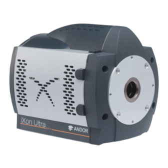
iXon Ultra 888 PRODUCT OVERVIEW SECTION 2: PRODUCT OVERVIEW 2.1 i ltRa The iXon Ultra 888 combines the largest available 1024 x 1024 EMCCD sensor, USB 3.0 and optimized electronics within the iXon platform along to provide the highest performance and reliability available for an EMCCD camera. Figure 2: iXon Ultra 888 EMCCD Camera Features of the iXon Ultra 888 include: •... -
Page 16: Power And Signal Connections
iXon Ultra 888 PRODUCT OVERVIEW 2.2 p oWeR and ignal onnections The power and signal connections are located on the base plate of the iXon Ultra 888: Figure 3: Power and Signal Connections of the Ixon Ultra 888 Power connector: For connection to the Power Supply Unit (PSU). Note the connector is keyed and has a locking action. USB 3.0: A USB connection should be made to the PC with the supplied USB 3.0 cable. -
Page 17: Camera Link
iXon Ultra 888 PRODUCT OVERVIEW NOTES: The cable termination at the customer end should be high impedance (>1KΩ) as an incorrect impedance match could cause errors with timing and triggering. The External Trigger Input is TTL level, CMOS compatible and has >10KΩ impedance. Signal diagrams of these connections are shown on Section 2.4. -
Page 18: External I/O
iXon Ultra 888 PRODUCT OVERVIEW 2.4 e XteRnal The iXon Ultra has a 26 way high density D-type connector to enable full functionality. Figure 4: iXon Ultra I/O connector Table 1: Pinouts for D-Type connector External Trigger I/O data bit 0 5 V Out Trigger Invert I/O data bit 1... -
Page 19: Signal Diagrams
iXon Ultra 888 PRODUCT OVERVIEW 2.5 s ignal iagRams 2.5.1 & o ltRa nput utput iming aRdWaRe Figure 5: External Trigger • VIH (High level input voltage, minimum) = 2.2V • VIL (Low level input voltage, maximum) = 0.88V • Change to falling edge trigger by connecting “Trigger Invert Input”... -
Page 20: Section 3: Installing The Ixon Ultra 888
iXon Ultra 888 INSTALLATION SECTION 3: INSTALLING THE IXON ULTRA 888 3.1 pc R equiRements Install the camera software before first connecting the camera – this will ensure that USB drivers are available when required. There are no restrictions on the order in which components are connected. It is best to allow a few seconds from camera power on (using either the button or a mains switch) to starting Solis in order for the camera to be recognised by the PC. -
Page 21: Cooling The Ccd
iXon Ultra 888 INSTALLATION 3.3 c ooling tHe Heat is generated by the sensor during normal operation which if not addressed may have a significant adverse effect on performance (e.g. signal to noise ratio and sensitivity) due to increased dark current noise. The iXon Ultra range makes use of a four-stage Peltier cooling assembly (thermoelectric cooler, TEC), which utilizes the thermoelectric effect to rapidly cool the sensor down to the stable operating temperature. -
Page 22: Minimum Achievable Temperatures
iXon Ultra 888 INSTALLATION 3.3.2 M inimum cHievable empeRatuRes The iXon Ultra 888 breaks new boundaries in the clocking speeds of EMCCDs and therefore the minimum achievable cooling will be impacted for some readout configurations. Clocking the image and storage regions of the sensor has by far the biggest impact on heat generation. -
Page 23: How To Determine The Minimum Achievable Temperature For Your
iXon Ultra 888 INSTALLATION The impact of the ROI and Binning parameters on minimum achievable CCD temperatures are shown for a range of examples in Table 2. Table 2: The effect of ROI type and size and Binning on minimum achievable CCD Temperature ROI Type Binning CCD Min (°C) -
Page 24: Connecting A Cooling System
iXon Ultra 888 INSTALLATION 3.4 C onnecting a ooling ystem 3.4.1 H onnections Two barbed coolant hose inserts are supplied as standard with the iXon Ultra camera, suitable for connection to 6 mm (0.25”) internal diameter soft PVC tubing / hose. Recommended tubing: 10 mm (0.4”) outside diameter, i.e. -
Page 25: Removing The Coolant Hoses
iXon Ultra 888 INSTALLATION 3.4.4 R emoving tHe oolant oses CAUTION: Before attempting to remove the hose connections, ensure that all water has been drained from the hoses and the coolant channel within the camera head. Care must be taken to avoid permanent damage to the camera system resulting from either leakage of coolant during connection / removal of hoses or spillage of any residual coolant contained within the camera head once the hoses have been removed. -
Page 26: Installing Andor Solis Software For Windows (Vista, 7 And 8)
iXon Ultra 888 INSTALLATION 3.6 i nstalling ndoR olis oftWaRe foR indoWs ista Terminate and exit any programmes that are running on the PC. Insert the Andor CD. The InstallShield Wizard now starts (this will vary slightly depending on your version of Windows software). - Page 27 iXon Ultra 888 INSTALLATION Select iXon Ultra, then click Next> and the following dialog box appears. Click Next > (alternatively, click on Browse…, choose your own shortcut destination then click Next >). Select (or de-select) the additional tasks to be performed during the set-up, then click Next>. Version 1.0 rev 27 Mar 2015...
- Page 28 iXon Ultra 888 INSTALLATION Click Install to continue with the installation (or click <Back, if you want to review / change any settings. When Install is pressed an update progress bar appears while the installation is performed, e.g. When the hardware installation is complete, the following screen appears. Version 1.0 rev 27 Mar 2015...
-
Page 29: New Hardware Wizard
iXon Ultra 888 INSTALLATION 3.7 n aRdWaRe izaRd When the first iXon Ultra camera is connected to a PC for the first time, the Found New Hardware Wizard screen appears: Select the ‘No, not this time only’ option then click Next> and the following screen appears: Select the ‘Install from a list or specified location (Advanced)’... - Page 30 iXon Ultra 888 INSTALLATION The installation wizard runs, e.g. When hardware installation is complete, the following screen appears. Click the Finish button to complete the installation. NOTE: If the camera is connected to a different USB port, steps 1 – 6 will have to be repeated on the first connection only.
-
Page 31: Start-Up Dialog
iXon Ultra 888 INSTALLATION 3.8 s taRt ialog On start-up of Solis software a dialog may appear (similar to that shown below) if multiple cameras are connected to your Figure 11: Start Up Dialog Menu Highlight the Andor iXon Ultra camera (The Serial Number can be found on the label on the camera) Click OK to continue with the selected camera. -
Page 32: Section 4: Triggering Information
iXon Ultra 888 TRIGGERING INFORMATION SECTION 4: TRIGGERING INFORMATION This section describes the Keep Clean Cycles and Triggering modes for the iXon Ultra 888. 4.1 k lean ycles iXon Ultra cameras have a range of different Keep Clean Cycles that run depending on the actual model and the state the camera is in. -
Page 33: Internal Keep Clean Cycle
iXon Ultra 888 TRIGGERING INFORMATION 4.1.2 i nteRnal lean ycle The second type of Keep Clean Cycle is called the Internal Keep Clean Cycle. It is performed between individual scans in a kinetic series, and is relevant to Non-Frame Transfer Mode combined with either Internal or Software Trigger. When the user configures a kinetics series acquisition, as well as defining the exposure time and the readout mode, they also define the number of scans to capture and the time between the scans. -
Page 34: External Keep Clean Cycle
iXon Ultra 888 TRIGGERING INFORMATION 4.1.3 e XteRnal lean ycle The third Keep Clean Cycle is the External Keep Clean Cycle. This cycle uses a different sequence of horizontal and vertical clocking, as it must be able to respond to external events extremely rapidly, but at the same time keep the image area of the sensor charge free. -
Page 35: Ixon Series Keep Clean Information
iXon Ultra 888 TRIGGERING INFORMATION 4.1.4 eRies lean nfoRmation The following table provides a summary of the differences in the keep clean cycles between the various iXon models. iXon x3 Ultra 897 Ultra 888 1 Vertical Shift 1 Vertical Shift 1 Vertical Shift Idle X Horizontal Shifts... -
Page 36: 4.2 Triggering Modes
iXon Ultra 888 TRIGGERING INFORMATION 4.2 tRiggeRing modes The iXon Ultra camera has several different triggering modes. These include Internal, External (and Fast External), External Start, External Exposure and Software Trigger. Note also that many of these features require iCam technology within the camera, fuller details of which can be viewed through www.andor.com In Internal Trigger the camera determines the exact time when an exposure happens, based on the acquisition... -
Page 37: Triggering Options In Frame Transfer (Ft) Mode
iXon Ultra 888 TRIGGERING INFORMATION 4.3 t (ft) m RiggeRing ptions in Rame RansfeR 4.3.1 i nteRnal RiggeRing Internal Triggering is the simplest mode of operation, in that the camera determines when the exposure happens. By monitoring the Fire output, the user can determine exactly when the camera is “exposing”. When the camera is idle, it runs the Idle Keep Clean Cycle (Section 4.1.1). -
Page 38: External Triggering
iXon Ultra 888 TRIGGERING INFORMATION 4.3.2 e XteRnal RiggeRing When the camera is idle, it runs the Idle Keep Clean Cycles described in Section 4.1.1. On receipt of the Start command from the PC, the camera goes into its External Keep Clean Cycles. The camera will repeat this these cycles a minimum of X times, where X is the number of image rows on the sensor, before it will accept any External Trigger events. - Page 39 iXon Ultra 888 TRIGGERING INFORMATION iCam Since all iXon Ultra cameras have iCam technology, the rising edge of the external trigger can occur before the end of the previous read out, provided that the falling edge of the Fire pulse occurs after the readout has completed, i.e. the External Trigger is only accepted up to the ‘User Defined Delay Period’...
-
Page 40: External Exposure Triggering
iXon Ultra 888 TRIGGERING INFORMATION 4.3.3 e XteRnal XposuRe RiggeRing External Exposure Triggering mode is distinct from the triggering modes discussed previously, in that the exposure period is fully controlled by the width of the external trigger pulse. The exposure period starts on the positive edge and concludes on the negative edge. -
Page 41: Triggering Options In Non-Frame Transfer (Nft) Mode
iXon Ultra 888 TRIGGERING INFORMATION 4.4 t (nft) m RiggeRing ptions in Rame RansfeR 4.4.1 i (nft) nteRnal RiggeRing In Internal Triggering (NFT) mode, when the camera is idle, it repeatedly runs the Idle Keep Clean Cycles. When the Start command is received from the PC, the camera completes the current Keep Clean Cycle, and then perform sufficient vertical shifts to ensure the Image and Storage regions are completely free of charge. -
Page 42: External & Fast External (Nft) Triggering
iXon Ultra 888 TRIGGERING INFORMATION 4.4.2 e & f (nft) t XteRnal XteRnal RiggeRing In the External Triggering modes, once an acquisition starts, the camera is goes into “External Keep Clean’ Cycle (see Section 4.1.3). As can be seen from Figure 20, the External Keep Clean Cycle runs continuously until the first external trigger event is detected;... -
Page 43: External Exposure (Nft) Triggering
iXon Ultra 888 TRIGGERING INFORMATION 4.4.3 e (nft) t XteRnal XposuRe RiggeRing External Exposure (NFT) mode is distinct from the triggering modes covered previously, in that the exposure period is fully controlled by the width of the external trigger pulse. The exposure period starts on the positive edge and concludes on the negative edge. -
Page 44: Software (Nft) Triggering
iXon Ultra 888 TRIGGERING INFORMATION 4.4.4 s (nft) t oftWaRe RiggeRing This mode is particularly useful when the user needs to control other equipment between each exposure and does not know in advance how long such control will take, or if the time taken changes randomly. With Software Trigger, the camera and software are in a high state of readiness and can react extremely quickly to a trigger event issued via software. -
Page 45: Triggering Options In Fast Kinetics (Fk) Mode
iXon Ultra 888 TRIGGERING INFORMATION 4.5 t (fk) m RiggeRing ptions in inetics 4.5.1 i (fk) nteRnal As Fast Kinetics uses both the Image and Storage areas as temporary storage areas, the number of options available is quite limited. The simplest mode is again Internal Trigger and, as with the internal trigger modes described previously, the system determines when the acquisition begins and then uses the exposure time defined by the user. -
Page 46: External (Fk)
iXon Ultra 888 TRIGGERING INFORMATION 4.5.2 e (fk) XteRnal In External Trigger mode, a trigger pulse is required to start each scan in the series. The rising edge of the trigger defines the trigger event. The user can delay the start of the vertical shifting relative to the trigger event. After the delay has elapsed, the number of rows (as specified by the user) are vertically shifted. -
Page 47: External Start (Fk)
iXon Ultra 888 TRIGGERING INFORMATION 4.5.3 e (fk) XteRnal taRt External Start triggering mode is a combination of External and Internal Trigger. At the start of the capture process, the camera runs the External Keep Clean Cycle, waiting for a trigger pulse to be applied to the External Trigger input. On receiving the trigger the exposure starts. -
Page 48: Ixon Triggering Data
iXon Ultra 888 TRIGGERING INFORMATION RiggeRing The following section provides delay time, jitter and sensor sweep times for different operating speeds and vertical shift speeds for the different models in the iXon series. 4.6.1 ltRa Vertical shift speed 4.33 µS Speed MHz Typical delay (µS) pk-pk Jitter (µS) -
Page 49: Ixon 3 (Du-897)
iXon Ultra 888 TRIGGERING INFORMATION 4.6.3 3 (du-897) Vertical shift speed 12.9 µS Speed MHz Typical delay (µS) pk-pk Jitter (µS) Sensor sweep time (ms) 11.20 +-3.4 11.30 +-3.4 11.67 +-3.4 13.28 +-3.6 Vertical shift speed 0.3 µS Speed MHz Typical delay (µS) pk-pk Jitter (µS) Sensor sweep time (ms) -
Page 50: Section 5: Troubleshooting
iXon Ultra 888 TROUBLESHOOTING SECTION 5: TROUBLESHOOTING 5.1 u nit does not sWitcH on • Check power cord is plugged in and connected correctly to mains supply • If applicable, replace fuse in the supplied mains cable as detailed in Section 6.2.4 •... -
Page 51: Camera High Fifo Fill Alarm
iXon Ultra 888 TROUBLESHOOTING 5.4 c fifo fill a ameRa laRm The Ixon Ultra 888 supports USB 3.0. The camera will function in a USB 2.0 port – but will not sustain the full camera frame rate. Camera High FIFO fill alarms will likely occur if the Ultra 888 is used with a USB 2.0 PC port. In addition, it has been observed in some systems that a camera may stop acquiring after approximately 1 - 10 seconds. -
Page 52: Section 6: Maintenance
iXon Ultra 888 MAINTENANCE SECTION 6: MAINTENANCE 6.1 c leaning ameRa XteRioR Only use a dry, clean, lint free cloth to clean the painted surfaces. If necessary, use a water diluted mild detergent to lightly dampen the cloth- do not use Isopropyl alcohol, solvents or aerosols. 6.2 R egulaR Hecks... -
Page 53: Section 7: Technical Specifications
iXon Ultra 888 SPECIFICATIONS SECTION 7: TECHNICAL SPECIFICATIONS 888 s ltRa pecifications Power supply ratings 100 - 240 V, 47 - 63 Hz, 1.6 A Location to be used Indoor use only Altitude Up to 2000 m Operating temperature range 0°C to 30°C Storage temperature -20°C to +55°C... -
Page 54: Appendix A: Mechanical Drawings
iXon Ultra 888 MECHANICAL DRAWINGS APPENDIX A: MECHANICAL DRAWINGS Version 1.0 rev 27 Mar 2015... -
Page 55: Appendix B: Dew Point Graph
iXon Ultra 888 DEW POINT GRAPH APPENDIX B: DEW POINT GRAPH The relationship between Relative Humidity and Dew Point at varying Ambient Temperature is shown below. This can be used to calculate the minimum temperature the cooling water should be set to. Figure 26:Calculation of dew point from ambient temperature and relative humidity For example, when using an iXon Ultra 888, you will need 10ºC cooling water to guarantee performance down to -95ºC In the relatively dry atmosphere of an air-conditioned lab, cooling water at 10ºC should not present any problems. -
Page 56: Appendix C: Emccd Technology
iXon Ultra 888 EMCCD TECHNOLOGY APPENDIX C: EMCCD TECHNOLOGY ccd? hat is an lectron ultiplying Electron Multiplying Charge Coupled Device (EMCCD) is a type of image sensor that is capable of detecting single photon events without an image intensifier (achievable by way of a unique electron multiplying structure built into the chip). - Page 57 iXon Ultra 888 EMCCD TECHNOLOGY rates than full frame devices, and have the advantage of a high duty cycle i.e. the sensor is always collecting light. A potential disadvantage of this architecture is the charge smearing during the transfer from the light-sensitive to the masked regions of the EMCCD (although they are significantly better than full frame devices).The smearing is more prevalent when exposure times are closer to the time taken to shift the charge under the mask (in the order of milliseconds).
- Page 58 iXon Ultra 888 EMCCD TECHNOLOGY herMoelectric ooler The iXon Ultra range has a four-stage Peltier cooling assembly, which utilizes the thermoelectric effect to rapidly cool the sensor down to the stable operating temperature. TE coolers have a cold side (in contact with the sensor) and a hot side.
-
Page 59: Appendix D: Glossary
iXon Ultra 888 GLOSSARY APPENDIX D: GLOSSARY This glossary provides an overview of the concepts and terminology used in Andor’s EMCCD technology. eMccd eadout equence of an In the course of readout, charge is moved vertically into the shift register then horizontally from the shift register into the output node of the amplifier. - Page 60 iXon Ultra 888 GLOSSARY a/d c onVersion Charge from the EMCCD is initially read as an analogue signal, ranging from zero to the saturation value. A/D conversion changes the analogue signal to a binary (digital) number, which can then be manipulated by the computer. ackground Background is a data acquisition made in darkness.
- Page 61 iXon Ultra 888 GLOSSARY The first area is the Image Area, which is located at the top and farthest from the readout register. This is the light sensitive area of the CCD. The second section is the Storage Area, and is located between the Image Area and the readout register. This section is covered by an opaque mask, usually a metal film, and hence is not sensitive to light.
- Page 62 iXon Ultra 888 GLOSSARY oise Shot Noise is due to the basic laws of physics and cannot be removed. Any signal, whether it is a dark signal or a light signal, will have shot noise associated with it. Shot noise is a statistical variation in signal level which follows a Poisson distribution.
- Page 63 iXon Ultra 888 GLOSSARY eadout Readout is the process by which data are taken from the pixels of the EMCCD and stored in computer memory. The pixels, which are arranged in a single row, are read out individually in sequence. Readout involves amplifying the charge on each pixel into a voltage, performing an analog to digital conversion and then storing the data in computer memory.
-
Page 64: Appendix E: Other Information
iXon Ultra 888 OTHER INFORMATION APPENDIX E: OTHER INFORMATION erMs and onditions of ale and arranty nforMation The terms and conditions of sale, including warranty conditions, will have been made available during the ordering process. The current version may be viewed at: http://www.andor.com/pdfs/literature/Andor_Standard_Warranty.pdf 2006 (Weee) aste...
Need help?
Do you have a question about the ANDOR iXon Ultra 888 and is the answer not in the manual?
Questions and answers