Table of Contents
Advertisement
Quick Links
Advertisement
Table of Contents

Related Manuals for Oxford Instruments Cryojet


Summary of Contents for Oxford Instruments Cryojet
- Page 1 Operator’s Handbook Cryojet Issue 4 January 2001 File reference: CJ250101.DOC Part number UMC0001 Oxford Instruments Superconductivity Tubney Woods, Abingdon, Oxon, OX13 5QX, England Tel: +44 (0)1865 393 200 Fax: +44 (0)1865 393 333 E-mail:superconductivity@oxinst.co.uk www.oxford-instruments.com...
-
Page 2: Table Of Contents
RS232 Connection Hardware ..............20 GPIB (IEEE-488) Connection Hardware ............ 20 Control Using the Oxford Instruments ObjectBench software package..................... 21 6.3.1 Installation of Cryojet driver in ObjectBench......21 6.3.2 Setting up the Cryojet driver ..........22 6.3.3 Control of the Cryojet ............22 Restoring Standard Calibration Parameters.......... - Page 3 Before you attempt to install or operate this equipment for the first time, please make sure that you are aware of the precautions that you must take to ensure your own safety. The booklet “Safety Matters”, supplied with this manual gives advice. Oxford Instruments Superconductivity Limited, January, 2001. All rights strictly reserved.
-
Page 4: Quick User Guide
Turn the automatic temperature control ON. The Cryojet will now cool to the set temperature. (To select Automatic mode, the sample flow must be at least 2l/min. If a flow has been selected but after a couple of minutes no flow can be felt, switch the temperature control off and see section 9.) - Page 5 Keep the plastic cap and the pressure relief valve in place on the dewar top fitting, to prevent the ports becoming blocked by ice. Alignment of Nozzle The nozzle should be placed as close to the sample as possible to prevent icing - 5 mm is recommended.
- Page 6 See Figure 2. Sample flow and shield flow start Auto-Start is useful if there is a possibility of brief as soon as Cryojet is turned on, power failures when the Cryojet is running with automatic temperature Do not select Auto-Start unattended.
-
Page 7: Description Of The System
Description of the system The Cryojet is designed principally for X-ray diffraction studies. It allows a sample to be cooled or heated using a stream of gas without the need for windows between the X-ray source, sample and detector. Figure 3 illustrates the system. -
Page 8: Sample Flow Unit
This shield flow then flows through the outer nozzle, preventing atmospheric water vapour from icing up the sample or the nozzle. Stand The Cryojet is supported via a stand that is adjustable to suit the geometry of the user’s experiment. Storage Dewar A 75 l storage dewar is used to store the liquid nitrogen used for the sample flow and shield flow. -
Page 9: Unpacking And Preparation
Unpacking and preparation Unpacking the system Carefully remove the Cryojet and all the accessories from the packing cases, and check the packing list to make sure that you have found all of the components. Examine the system to make sure that it has not been damaged since it left the factory. If you find any signs of damage please contact Oxford Instruments immediately. - Page 10 Tighten the three small screws on the dewar top fitting. i) Fit a suitable hose from your pressurised supply dewar to the Cryojet dewar. Some users use polythene tube. This becomes brittle when cold, and must be used with caution.
- Page 11 j) If you are using a level probe, first remove the screw in the side of the probe. Insert the probe through the stepped tube on the dewar top fitting. (Remove the pressure relief valve if one has been fitted.) Push down firmly until the level probe is as far down as it will go, and does not wobble.
- Page 12 tilt adjust Coarse xyz fine height adjustment dj t DETAIL Figure 6 Coldhead and stand (The appearance of the knobs may be different from that illustrated.) Figure 7 Close-up of stand assembly...
-
Page 13: Controller
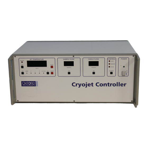
Controller Full details are in the Cryojet Controller Technical Handbook, included together with this manual. See also Figure 1. Control of flow rates The flow rates of the sample flow and shield flow are shown on the display in l/min (as if they were measured at atmospheric pressure and 293 K). -
Page 14: Default Conditions On Start-Up
Gas flows non-zero - can be configured to any desired value. Heat exchanger in Automatic mode Auto-Start is useful if there is a possibility of brief power failures when the Cryojet is Do not select Auto-Start unless you are sure that there running unattended. -
Page 15: Operation
Operation Suggested operating conditions Always keep at least 10 cm of liquid in the dewar when the Cryojet is running, as lower levels could impair the performance. Never allow the dewar to become empty when the Cryojet is running. Keep the plastic cap, the vent valve and the pressure relief valve (or level probe) in place on the dewar top fitting, to prevent water from the atmosphere entering. -
Page 16: Filling The Dewar
Figure 8 Possible alignment technique Filling the dewar The Cryojet can be run continuously for as long as required. The dewar can be refilled while the Cryojet is running. Fit the liquid nitrogen hose from your supply dewar onto or into the fill tube. Make sure it is held in place so that it will not be blown free by the pressure of nitrogen during the fill. -
Page 17: Warming Up The System
To speed this up, reduce the sample flow to about 3 l/min. If you do not use the Cryojet for several days, the dewar can warm up. It is then possible for water to collect at the bottom. This could block the system when it freezes, although the dewar legs have been designed to prevent this. -
Page 18: Evacuating The Outer Vacuum Chamber (Ovc)
If the Cryojet has not been used for a month or more and the dewar has warmed up, it is often advisable to pump the vacuum in the sample flow unit before starting to use it again. -
Page 19: Calibration Of Sample Temperature
Contact Oxford Instruments for calibration information. Stability The temperature displayed is normally stable to about 0.1 K. Small fluctuations in temperature will occur when the dewar is refilled. -
Page 20: Control From A Computer
GPIB cable, conforming to the standard IEEE-488.1. Connections should be made using a standard GPIB cable. If you wish to connect both a Cryojet controller and a level meter to a GPIB port on a computer, use a “GPIB Gateway” - contact your sales engineer or Oxford Instruments Cryospares. -
Page 21: Control Using The Oxford Instruments Objectbench Software Package
Control Using the Oxford Instruments ObjectBench software package ObjectBench is provided with the Cryojet. This section describes how to install and run the Cryojet driver in ObjectBench. For other information, see the ObjectBench manual. 6.3.1 Installation of Cryojet driver in ObjectBench... -
Page 22: Setting Up The Cryojet Driver
6.3.3 Control of the Cryojet The Cryojet instrument driver in ObjectBench is intended to be self-explanatory. Control of the instrument may either be LOCAL from the front panel, or REMOTE via the computer interface. The LOC/REM button may be used to switch between LOCAL and... -
Page 23: Restoring Standard Calibration Parameters
ObjectBench software. Use the following sequence of operations and menu selections. This feature is not available from the Cryojet instrument driver. Instead, you must add the instrument driver called ITC503.drv (using Configure / Add/remove instrument / Add). -
Page 24: Setting Of P, I And D Control Terms
Setting of P, I and D Control Terms The PROPORTIONAL, INTEGRAL and DERIVATIVE control terms may be displayed and set by means of the recessed P, I and D buttons. Use a pointed object to press these buttons. The system is already set with optimised values of these parameters: it should not be necessary to change them, or to read the rest of this section. - Page 25 d) Time the period of oscillation (in minutes). This is a measure of the response time of the system. e) Set I to a value approximately equal to the response time. Then increase the P setting to a point where oscillation just ceases. Note the value of P at this point, then set it to approximately double this value.
-
Page 26: Liquid Nitrogen Autofill System
The level meter has already been set up to function correctly in the 75 litre Cryojet dewar. The display shows the depth of liquid, expressed as a percentage of the maximum depth, which is 805 mm for the standard 75 litre Cryojet dewar. -
Page 27: Setting Up The Autofill System
Setting Up the Autofill System Your pressurised dewar must be equipped with a pressure regulator or pressure relief valve which will ensure that the pressure does not exceed 1.5 bar. If the dewar has a pressure build circuit, you may not need to use it, as adequate pressure will build up naturally. -
Page 28: The Solenoid Valve
Note: This will increase the temperature fluctuation caused by filling. The autofill is ready for use. If the Cryojet dewar is below the FILL level, it will start to fill. The Solenoid Valve The valve is closed when no power is supplied to it. When the solenoid valve is energised (open) for a long period it will become very hot. -
Page 29: Fault Finding
“Lo N” appears on the There is less than 6 cm of liquid in the dewar. Do not controller operate the Cryojet with less than 10 cm of liquid. Refill the dewar, then switch the controller off and on again. - Page 30 The temperature stays at room Check that cable from the controller to the coldhead temperature, even though the is plugged in correctly, and that there is liquid sample flow is not set to zero. nitrogen in the dewar. The heat exchanger could be blocked with moisture from the atmosphere, if it was switched off while cold.
- Page 31 Cryostat will not reach its Check that there is at least 10 cm of liquid in the specified base temperature storage dewar. Move the dewar so that the curve of the flexible transfer tube is as gentle as possible - avoid sharp bends.
-
Page 32: Wiring Information
D-plugs. The 15 way D-sockets on the controller labelled “Cryojet dewar leg” and “Shield unit” are identical. You can monitor voltage outputs to the coldhead while the jet is running by disconnecting the shield unit from the controller (or vice versa), and connecting a voltmeter across the pins of the socket you have disconnected. - Page 33 10.2 Sample flow unit: 15 way D-connector (labelled “Cryojet dewar leg”) Component Pins on 15 Pins on 4-pin round Typical Typical output way D- connector fixed to resistance of controller connector dewar leg of between pins, measured using sample flow unit...
Need help?
Do you have a question about the Cryojet and is the answer not in the manual?
Questions and answers