
Related Manuals for Oxford Instruments PlasmalabSystem100


Summary of Contents for Oxford Instruments PlasmalabSystem100
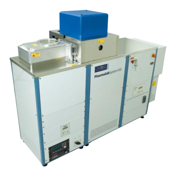
- Page 1 PlasmalabSystem100 Modular Cluster System – TEOS Installation Data Issue 10: February 2011...
-
Page 2: Table Of Contents
Installation Data PlasmalabSystem100 Oxford Instruments Plasma Technology Contents Page Introduction ......................3 Installation information ................... 4 Dimensions ......................4 Weights ......................4 Heat load ......................4 Services connections ....................8 Gas handling ......................10 Services ........................ 14 Electrical Supply requirement ................14 Water Cooling requirement ................ -
Page 3: Introduction
NOTE: All information, services, dimensions etc., refer only to the PlasmalabSystem100, i.e. plasma processing at up to 200 mm wafers in MESC compatible chambers. Consider access when planning the system installation. Ensure that good access is available to parts of the system that require maintenance. Ensure that all isolation points for the system services are easily accessible. -
Page 4: Installation Information
Installation Data PlasmalabSystem100 Oxford Instruments Plasma Technology Installation information Dimensions System dimensions are given in Fig 1, Fig 2 and Fig 3. Gas handling component dimensions are given in Fig 6, Fig 7 and Fig 8. Teos pod and TEOS oven dimensions are given in Fig 9 and Fig 10 respectively. -
Page 5: Fig 1: Pecvd System Layout (3-Frame Base Pressure Turbo Configuraton)
Installation Data Oxford Instruments Plasma Technology PlasmalabSystem100 1630 SERVICE ACCESS OIPT RECOMMENDS THAT AT LEAST 600mm SERVICE ACCESS SPACE IS ALLOWED BETWEEN ANY OBSTACLE (E.G. WALLS, PARTITIONS, ETC.) AND SERVICEABLE ITEMS, E.G. THE POWER DISTRIBUTION UNIT. 1412 Fig 1: PECVD system layout (3-frame Base pressure turbo configuraton) -
Page 6: Fig 2: Pecvd System Layout (2-Frame)
Installation Data PlasmalabSystem100 Oxford Instruments Plasma Technology 1090 SERVICE ACCESS OIPT RECOMMENDS THAT AT LEAST 600mm SERVICE ACCESS SPACE IS ALLOWED BETWEEN ANY OBSTACLE (E.G. WALLS, PARTITIONS, ETC.) AND SERVICEABLE ITEMS, E.G. THE POWER DISTRIBUTION UNIT. 1412 Fig 2: PECVD system layout (2-frame) -
Page 7: Fig 3: Pecvd Layout (2-Frame Cluster Upgradeable)
Installation Data Oxford Instruments Plasma Technology PlasmalabSystem100 1795 SERVICE ACCESS OIPT RECOMMENDS THAT AT LEAST 600mm SERVICE ACCESS SPACE IS ALLOWED BETWEEN ANY OBSTACLE (E.G. WALLS, PARTITIONS, ETC.) AND SERVICEABLE ITEMS, E.G. THE POWER DISTRIBUTION UNIT. 1412 Fig 3: PECVD Layout (2-frame cluster upgradeable) -
Page 8: Services Connections
Installation Data PlasmalabSystem100 Oxford Instruments Plasma Technology Services connections TOP ELECTRODE 3/8“ SWAGELOK & AMU COOLING 3/8“ SWAGELOK LF GENERATOR COOLING 3/8“ SWAGELOK PROCESS CHAMBER (Only used if COOLING chamber cooling is fitted) 1/4“ SWAGELOK (Only used if TURBO COOLING... -
Page 9: Fig 5: Electrical Connections
Installation Data Oxford Instruments Plasma Technology PlasmalabSystem100 POWER DISTRIBUTION UNIT (REMOVABLE COVER) SYSTEM POWER CABLE GLAND (CABLE LENGTH = 4 METRES) SKT 9 SKT 7 SKT 10A SKT 10 COOLING EARTH TERMINAL 2 AMP 2 AMP 2 AMP SKT 8... -
Page 10: Gas Handling
Installation Data PlasmalabSystem100 Oxford Instruments Plasma Technology Gas handling IMPORTANT OIPT gas pods typically weigh >40kg. If you intend fixing your gas pod to a wall, ensure the wall and gas pod fixings are sturdy enough to bear at least four times the weight of the gas pod. Periodically, e.g. annually, check the gas pod and its fixings are secure. -
Page 11: Fig 7: 8-Line Gas Pod
Installation Data Oxford Instruments Plasma Technology PlasmalabSystem100 100 mm DIAMETER EXTRACTION COLLAR SECONDARY GAS OUTLET LINE TO SYSTEM (ONLY USED IF A SPLIT MANIFOLD IS FITTED) ¼" 988.7 GAS 8 918.4 GAS 7 848.1 GAS 6 GAS INLET LINES 777.8 (¼"STAINLESS... -
Page 12: Fig 8: 12-Line Gas Pod
Installation Data PlasmalabSystem100 Oxford Instruments Plasma Technology 100 mm DIAMETER EXTRACTION COLLAR SECONDARY GAS OUTLET LINE TO SYSTEM (ONLY USED IF A SPLIT MANIFOLD IS FITTED) 42.3 ¼" 1269.9 GAS 12 1199.6 GAS 11 1129.3 GAS 10 1059 GAS 9 988.7... -
Page 13: Fig 9: Teos Pod
Installation Data Oxford Instruments Plasma Technology PlasmalabSystem100 EXTRACTION NOTES: COLLAR MAXIMUM DISTANCE OF TEOS POD FROM MAIN UNIT IS 2 METRES ALL GAS LINES ARE 1/4“ STAINLESS STEEL TUBE, PROTRUDING 160 mm FROM POD FOR WELDING MAINS CABLE TO MAIN UNIT... -
Page 14: Services
The required services are listed in the following sub-sections. For full details of services specifications including connection diagrams, electrical connection schematic etc., read in conjunction with the Oxford Instruments Plasma Technology ‘Services Specifications for Plasmalab and Ionfab Systems’ document. Electrical Supply requirement... -
Page 15: Nitrogen Requirement
Installation Data Oxford Instruments Plasma Technology PlasmalabSystem100 Nitrogen requirement Function Connection Parameter Specification System N ¼” stainless steel Flow 8 lpm (0.32 cfm) Swagelok Pressure 3.0 Bar (45 psi) minimum Rotary pump purge ¼” stainless steel Flow Refer to sub-section... -
Page 16: Pump Set Information
Oxford Instruments Plasma Technology Pump set information CAUTION Where the rotary vane or Roots pumps are powered from a mains supply separate from the PlasmalabSystem100, a separate 'emergency off' facility must be provided by the customer. Process pump options Available... - Page 17 Installation Data Oxford Instruments Plasma Technology PlasmalabSystem100 Loadlock and wafer-handler pump options Available Length Width Height Pump inlet *Pump Weight Water Power **Minimum pump connection outlet cooling consumption purge options connection rate Adixen DN 25 DN 25 0.45 (50Hz) 2 lpm 2015C2 0.55 (60Hz)
-
Page 18: Heater/Chiller Information
Installation Data PlasmalabSystem100 Oxford Instruments Plasma Technology Heater/chiller information Chiller Width Length Height Weight Usable Water Electrical Temperature Connections Requirements Range °C Julabo FP51 -30 to 80 3/8” 400V, 50Hz, 3 Phase, Swagelok 14 Amps 230V, 60Hz, Julabo FP51 -30 to 80 3/8”... - Page 19 Installation Data Oxford Instruments Plasma Technology PlasmalabSystem100 Part Number Fluid Usable Temperature Recommended Range Application 94-G-WTR-SUN-909 Thermal G -30 to 80°C FL601. FP51 when fitted to systems with electrically heated tables and the automatic liquid nitrogen changeover unit (ACU). 94-G-WTR-SUN-903 Thermal H5 -50 to 105°C...
-
Page 20: Plc Interlock Chain
Installation Data PlasmalabSystem100 Oxford Instruments Plasma Technology PLC interlock chain General description The interlocks form a continuous 24Vdc chain, which must be complete before the process gases and RF power supplies are enabled. An output to disable external devices unless the lid/ hoist is closed is also provided; this is typically used to disable a lid- mounted endpoint detector laser. - Page 21 Installation Data Oxford Instruments Plasma Technology PlasmalabSystem100 RF enable interlock chain details are given in Table 1; Refer to drawing 94-SE00A26865 (PC2003 interface schematic). INTERLOCK DEVICE PCB1 Link out Comments input Vacuum Vacuum Switch BLK17 NONE Pressure below 600 mBar...
-
Page 22: Gas Box Interlocks
Installation Data PlasmalabSystem100 Oxford Instruments Plasma Technology Gas box interlocks Refer to drawing: 94-SE81B26657 (PC2003 gas pod loom). To enable process gases, the RF interlock chain must be complete. The gas box interlock is shown in Fig 11. SYSTEM CONSOLE... -
Page 23: System Link Configuration Table
Installation Data Oxford Instruments Plasma Technology PlasmalabSystem100 8.2.2 System Link Configuration Table NAME FUNCTION NOTES ANALOGUE 0V TO CHASSIS DIGITAL 0V TO ANALOGUE 0V NON – CONTROLLER CRYO ENABLE HEATER SNAP SWITCH BYPASS FIT IF NO OEM CONTROLLER LK6 A/B... -
Page 24: System Led Monitoring Table
Installation Data PlasmalabSystem100 Oxford Instruments Plasma Technology 8.2.3 System LED Monitoring Table NAME COLOUR MONITORING LED1 GREEN +24V DC LED2 +15V DC LED3 YELLOW -15V DC LED4 GREEN +5V DC LED5 CM COMP OK LED6 PUMP CURRENT SWITCH LED7 N2 PRESSURE SWITCH...
Need help?
Do you have a question about the PlasmalabSystem100 and is the answer not in the manual?
Questions and answers