Table of Contents
Advertisement
Quick Links
Advertisement
Table of Contents

Related Manuals for 1 Sound Contour CT28


Summary of Contents for 1 Sound Contour CT28
- Page 1 Contour CT28 Wall & Ceiling Installation...
-
Page 2: Table Of Contents
Contents Chapter 1. Contour CT28..............3 CT28 Specifications................3 Chapter 2. Accessories...............4 CT28 Wall Bracket................. 4 ....................4 CT28 Horizontal Mounting Bracket..........4 ....................4 CT28 Angle Bar................4 ....................4 Chapter 3. Installing CT28 on the Wall Bracket........5 Critical information................5 Products, accessories and tools required........5 Procedures..................5... -
Page 3: Chapter 1. Contour Ct28
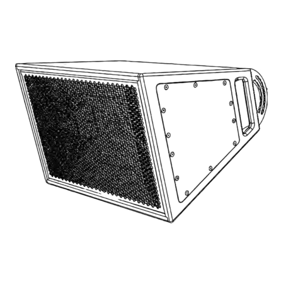
Chapter 1. Contour CT28 Horn-Loaded Point Source Speaker Enclosure Figure 1. Contour CT28 The Contour CT28 is a compact, 3-way passive loudspeaker capable of delivering a maximum SPL of 140 dB. This is a powerful speaker that sounds intimate at lower volumes. -
Page 4: Chapter 2. Accessories
• 4 × M8 stainless steel lock nuts This bracket attaches to the rear of the Contour CT28 enclosure and mounts to a wall. It allows for variable positioning on both the horizontal and vertical axes. The vertical positioning can be tilted down to 25°. The bracket is made from stainless steel 316, or galvanized zinc plated steel with black or white powder coating. -
Page 5: Chapter 3. Installing Ct28 On The Wall Bracket
Restriction: Only hardware and accessories included with the product or specified by 1 Sound should be used for its installation. - Page 6 CONTOUR CT28 WALL & CEILING INSTALLATION Figure 6. Removing the bottom M4 pan-lock bolt. Figure 7. Removing the top M4 pan-lock bolt. • Use a 3 mm hex wrench to loosen and remove the M4×16 mm pan-lock bolt from the bottom of the bracket. Be sure to keep this bolt, as it will be necessary to fix the pan angle when the installation is completed.
- Page 7 | 3 - INSTALLING CT28 ON THE WALL BRACKET Figure 8. Removing the bottom M8 pivot bolt. Figure 9. Removing the top M8 pivot bolt. • Likewise, remove the M8×25 mm pivot bolt and its washer from • Then use a 5 mm hex wrench to remove the M8×25 mm pivot the bottom of the bracket, and keep them for the installation.
- Page 8 CONTOUR CT28 WALL & CEILING INSTALLATION Figure 10. Separating the tilt assembly from the wall Figure 11. Loosening the tilt-lock bolt. yoke. • The tilt assembly should come away from the yoke. Note: Before mounting the tilt assembly to the CT28 enclosure, it is recommended that you unlock the tilt mechanism to ensure that it moves properly.
- Page 9 | 3 - INSTALLING CT28 ON THE WALL BRACKET Figure 12. Removing the tilt-lock bolt. Figure 13. Verifying the movements of the tilt mechanism. • Swing down the tilt arm to verify the free movement of the components of the tilt mechanism. As the rotating bracket and the tilt arm move with respect to each other, the moving cam should slide up and down the tilt arm and within the rotating bracket with negligible resistance.
-
Page 10: Installing The Tilt Arm Assembly On The Ct28
CONTOUR CT28 WALL & CEILING INSTALLATION Figure 14. Verifying the movement of the cam in the Figure 15. The rear panel of the CT28 with the tilt arm. mounting points for the bracket indicated. • Lay the enclosure on its front grille, taking whatever necessary precautions to avoid damaging the finish of the cabinet or the grille. - Page 11 | 3 - INSTALLING CT28 ON THE WALL BRACKET Figure 16. Removing the M6 mounting bolts from Figure 17. Removing the M6 bolts from the bottom the top of CT28. (connector end) of the CT28 • Using a 4 mm hex wrench or hex driver, remove the two M6 ×...
- Page 12 CONTOUR CT28 WALL & CEILING INSTALLATION • Align the four holes in the mounting ears of the tilt arm with the Figure 18. Aligning the tilt arm and M6 bolts with the M6 rigging points on the CT28 M6 rigging points from which the screws have been removed.
- Page 13 | 3 - INSTALLING CT28 ON THE WALL BRACKET Fixing the Tilt Angle Figure 21. The holes corresponding to the selectable tilt angles. It is necessary to fix the desired tilt angle before installing the tilt arm assembly on the CT28 enclosure. the tilt angle of the Wall Bracket can be adjusted from 0°...
-
Page 14: Installing Redundant Safety Anchors
CONTOUR CT28 WALL & CEILING INSTALLATION Figure 22. Re-inserting the tilt-locking bolt in the the M5 rigging points on the top of the CT28 enclosure for this holes corresponding to the selected angle (-25° purpose. shown). In most cases of wall mounting a single CT28 enclosure, the use of a steel wire rope safety bridle will provide sufficient redundant safety. -
Page 15: Installing The Wall Bracket To The Wall
| 3 - INSTALLING CT28 ON THE WALL BRACKET Figure 26. Removing the M5×25 mm countersunk Figure 27. Inserting the M5 eye screws for the installation of safety anchors. bolts in the rigging points on the top of the CT28 enclosure. •... - Page 16 Notice: Due to the wide variety of building materials and construction methods that can be encountered in an installation, 1 Sound can only provide general recommendations for installing the Wall Bracket. It is the responsibility of the installer to assess the appropriate stability and sturdiness of the installation.
- Page 17 | 3 - INSTALLING CT28 ON THE WALL BRACKET • When it has been verified that there is no wiring or plumbing Figure 32. Driving the screw anchors into the wall. in the wall behind the mounting position, use the plate itself as a drilling template and mark with the pencil the centers and outlines of the mounting holes.
-
Page 18: Installing And Pointing Ct28 On The Wall Bracket
CONTOUR CT28 WALL & CEILING INSTALLATION Figure 33. Tightening the screw anchors with a Figure 34. Applying downward force to verify the torque wrench. mount. • Using a torque wrench, tighten each screw anchor into the wall. Take care not to exceed the maximum installation torque specified by the manufacturer of the hardware. - Page 19 | 3 - INSTALLING CT28 ON THE WALL BRACKET Figure 37. Tightening the bottom CAUTION pivot bolt. Two People Required The following task simultaneously requires moderate two-handed lifting and the performance of fine motor operations. To avoid possible injury or damage, this procedure must be performed by two people.
- Page 20 CONTOUR CT28 WALL & CEILING INSTALLATION Fixing the pan angle Figure 42. The holes corresponding to the selectable pan angles (overhead view). Once the pivot bolts have been installed and tightened, the CT28 must be fixed at the required pan angle to achieve the desired coverage.
-
Page 21: Attaching A Safety Bridle
| 3 - INSTALLING CT28 ON THE WALL BRACKET Figure 44. Tightening the bottom pan-lock bolt. Attaching a safety bridle If the CT28 speaker enclosure has been equipped with eye bolts for a redundant safety bridle (steel wire rope), these must be attached to the external anchor before concluding the installation. -
Page 22: Chapter 4. Installing Ct28 On The Horizontal Mounting Bracket
Keep these bolts, as the will be Restriction: Only hardware and accessories included with required to reassemble the bracket once it is installed. the product or specified by 1 Sound should be used for its installation. Restriction: Do not modify or alter the loudspeaker or any accessory. -
Page 23: Installing The Horizontal Bracket On The Ct28
| 4 - INSTALLING CT28 ON THE HORIZONTAL MOUNTING BRACKET Figure 50. Removing the end plates from the wall- Figure 51. The rear panel of the CT28 with the mount yoke . mounting points for the bracket indicated. • Once the plate has been removed completely from one end of the bracket, repeat the above process to remove the plate from the opposite end. - Page 24 CONTOUR CT28 WALL & CEILING INSTALLATION Figure 52. Removing the mounting screws from the Figure 53. Installing the Horizontal Bracket plates top of CT28. on the CT28. • Insert the two M6 x 25 mm screws previously removed, and thread them into the enclosure through the mounting holes in the bracket end.
- Page 25 | 4 - INSTALLING CT28 ON THE HORIZONTAL MOUNTING BRACKET Figure 55. Removing the M6 bolts from the bottom (connector end) of the CT28 Figure 56. The plates of the Horizontal Bracket installed on the CT28. • Repeat the previous four steps on the opposite (bottom/ connector side) end of the CT28.
-
Page 26: Installing Redundant Safety Anchors
CONTOUR CT28 WALL & CEILING INSTALLATION Installing redundant safety anchors Figure double-swivel hoist ring measurement requirements. Attention: When correctly installed, the Wall Bracket and the Horizontal Mounting Bracket are designed to safely support the CT28 speaker enclosure under normal conditions. However,... -
Page 27: Installing The Horizontal Bracket To The Wall
| 4 - INSTALLING CT28 ON THE HORIZONTAL MOUNTING BRACKET Figure 61. Torquing the hoist rings. • Using a 3 mm hex wrench, remove the two rear M5×25 mm • Tighten the two hoist rings into the rigging points to the to countersunk screws from the top of the CT28 enclosure. - Page 28 Notice: Due to the wide variety of building materials and construction methods that can be encountered in an installation, 1 Sound can only provide general recommendations for installing the Horizontal Mounting Bracket. It is the responsibility of the installer to assess the appropriate stability and sturdiness of the installation.
- Page 29 | 4 - INSTALLING CT28 ON THE HORIZONTAL MOUNTING BRACKET Figure 66. Marking the mounting surface for Figure 68. Correctly orienting the Bracket yoke. drilling. • Insert the four screws or anchors directly through the mounting holes in the rear plate of the yoke, tightening the screw anchors •...
-
Page 30: Installing And Pointing Ct28 On The Horizontal Mounting Bracket
CONTOUR CT28 WALL & CEILING INSTALLATION Figure 70. Tightening the screw anchors with a Figure 72. Lifting the CT28 onto the wall-mounted torque wrench. yoke. Figure 73. Fitting the CT28 with plates onto the yoke of the Horizontal Mounting Bracket (Top View). - Page 31 | 4 - INSTALLING CT28 ON THE HORIZONTAL MOUNTING BRACKET Figure 74. Aligning the lug on the angle-adjustment Figure 76. The tilt-locking holes and their plate with the hook on the wall-mounted yoke. corresponding angles (0° being perpendicular to wall). •...
- Page 32 CONTOUR CT28 WALL & CEILING INSTALLATION • Using a 4 mm hex wrench, tighten the first bolt firmly into the Figure 78. Example alignment of an odd angle (-15°). bracket, so that the head of the bolt is inside the hole and will prevent upward or downward tilt of the bracket.
-
Page 33: Attaching A Safety Bridle
| 4 - INSTALLING CT28 ON THE HORIZONTAL MOUNTING BRACKET • Once the two primary bolts have been inserted to fix the tilt Figure 83. Tightening the secondary bolts (-10° tilt angle, the secondary bolts should be inserted on each side angle shown). - Page 34 CONTOUR CT28 WALL & CEILING INSTALLATION ATTENTION A redundant safety must be anchored to a point higher than the enclosure and, where possible, to a separate structural member than the Bracket. If the secondary safety bridle must be anchored using...
-
Page 35: Chapter 5. Installing Ct28 On The Horizontal Mounting Bracket And Angle Bar
Restriction: Only hardware and accessories included with the product or specified by 1 Sound should be used for its installation. Restriction: Do not modify or alter the loudspeaker or any accessory. -
Page 36: Installing The Horizontal Bracket On The Ct28
CONTOUR CT28 WALL & CEILING INSTALLATION Figure 85. Removing the M6 bolts from the Figure 88. The rear panel of the CT28 with the Horizontal Mounting Bracket. mounting points for the bracket indicated. Figure 86. Removing the end plates from the wall- mount yoke. - Page 37 | 5 - INSTALLING CT28 ON THE HORIZONTAL MOUNTING BRACKET AND ANGLE BAR Figure 89. Removing the mounting screws from the Figure 90. Installing the Horizontal Bracket plates top of CT28. on the CT28. • Insert the two M6 x 25 mm screws previously removed, and thread them into the enclosure through the mounting holes in the bracket end.
- Page 38 CONTOUR CT28 WALL & CEILING INSTALLATION Figure 92. Removing the M6 bolts from the bottom (connector end) of the CT28 Figure 93. The plates of the Horizontal Bracket installed on the CT28. • Repeat the previous four steps on the opposite (bottom/...
-
Page 39: Installing Redundant Safety Anchors
| 5 - INSTALLING CT28 ON THE HORIZONTAL MOUNTING BRACKET AND ANGLE BAR Installing redundant safety anchors Figure double-swivel hoist ring measurement requirements. Attention: When correctly installed, the Wall Bracket and the Horizontal Mounting Bracket are designed to safely support the CT28 speaker enclosure under normal conditions. -
Page 40: Installing The Angle Bar
CONTOUR CT28 WALL & CEILING INSTALLATION Figure 98. Torquing the hoist rings. • Using a 3 mm hex wrench, remove the two rear M5×25 mm • Tighten the two hoist rings into the rigging points to the to countersunk screws from the top of the CT28 enclosure. - Page 41 Notice: Due to the wide variety of building materials and construction methods that can be encountered in an installation, 1 Sound can only provide general recommendations for installing the Angle Bar. It is the responsibility of the installer to assess the appropriate stability and sturdiness of the installation.
- Page 42 CONTOUR CT28 WALL & CEILING INSTALLATION • When it has been verified that there is no wiring or plumbing in Figure 103. The clearance and drilling template of the wall-mounted face of the CT28 Angle Bar. the wall or ceiling behind the mounting position, use the Angle Bar itself as a drilling template and mark with the pencil the centers and outlines of the mounting holes.
- Page 43 | 5 - INSTALLING CT28 ON THE HORIZONTAL MOUNTING BRACKET AND ANGLE BAR • Drill the eight holes, using a drill or percussion drill with a bit Figure 108. Driving the screw anchors into the appropriate to the substrate material (masonry/concrete, wood, ceiling.
- Page 44 CONTOUR CT28 WALL & CEILING INSTALLATION Figure 109. Tightening the screw anchors with a Figure 111. Aligning the Yoke with the Angle Bar in torque wrench. the wall-mount configuration. Figure 112. Mounting the yoke of the Horizontal Mounting Bracket to the Angle Bracket (ceiling configuration shown).
-
Page 45: Mounting And Pointing The Ct28
| 5 - INSTALLING CT28 ON THE HORIZONTAL MOUNTING BRACKET AND ANGLE BAR Figure 114. Applying downward force to verify the Figure 116. Fitting the CT28 with plates onto the mount. yoke of the Horizontal Mounting Bracket (Top View). • Apply force or weight to the mounting yoke to verify physically its ability to support the necessary load. - Page 46 CONTOUR CT28 WALL & CEILING INSTALLATION Figure 118. Positioning the CT28 for the required Figure 120. The tilt-locking holes and their coverage (-30° shown). corresponding angles wall-mounted configuration (0° = perpendicular to wall). • As one person holds and tilts the speaker enclosure, the second...
- Page 47 | 5 - INSTALLING CT28 ON THE HORIZONTAL MOUNTING BRACKET AND ANGLE BAR • Using a 4 mm hex wrench, tighten the first bolt firmly into the Figure 122. Example alignment of an odd angle (-45° ceiling mount shown) . bracket, so that the head of the bolt is inside the hole and will prevent upward or downward tilt of the bracket.
- Page 48 CONTOUR CT28 WALL & CEILING INSTALLATION Figure 125. Tightening the locking bolt on the opposite side (-40° shown). • When these two secondary bolts are threaded into the Bracket, use a 4 mm hex wrench to tighten them securely. These two...
-
Page 49: Attaching A Safety Bridle
| 5 - INSTALLING CT28 ON THE HORIZONTAL MOUNTING BRACKET AND ANGLE BAR Figure 128. An example of a steel wire rope safety bridle attached using carabiners. • It is now safe to release the speaker enclosure and verify the stability and security of the installation.