
Related Manuals for Omega MICROMEGA CN77000 series


Summary of Contents for Omega MICROMEGA CN77000 series
- Page 1 User’ s Guide Shop on line at ® ® www.omega.com e-mail: info@omega.com www.omega.com/software MICROMEGA ® CN77000 Series Controller...
- Page 2 It is the policy of OMEGA to comply with all worldwide safety and EMC/EMI regulations that apply. OMEGA is constantly pursuing certification of its products to the European New Approach Directives. OMEGA will add the CE mark to every appropriate device upon certification.
- Page 3 To Order Model CN77000 SERIES CONTROLLER (Specify Model Number) PROCESS CONTROLLER, DUAL DISPLAY FOR THERMOCOUPLE, RTD, VOLTAGE OR CURRENT INPUTS IN A 1/16 DIN CASE Model No. Description cont. Model No. Description OPTIONAL OUTPUTS CN77 Dual displays for simultaneous display of measured value and setpoint. none (no entry required) Selectable preset tune, adaptive tune, autotune, PID, PI, PD control modes.
- Page 4 NOTES...
- Page 5 ABLE OF ONTENTS Part 1: Introduction Safety Considerations .................1 Before You Begin..................2 Part 2: Setup Mounting the Controller...............4 Front Panel View ..................7 ................7 Front Panel Annunciators Rear Panel View..................8 ..............9 Rear Panel Connector Labels Mechanical Installation ..............10 ................10 Dip Switch Configuration ..................11 Dip Switch Settings ............
- Page 6 ABLE OF ONTENTS Part 3: Operation: Configuration Mode Introduction ..................16 ..........16 Turning Your Controller on for the First Time ..............17 Function in Configuration Mode Menu Configuration................18 .....................19 ID Number ....................20 Set Points ..............24 Input Type (Thermocouple) ..................25 Input Type (RTD) ................26 Input Type (RTD Value) ................27...
- Page 7 ABLE OF ONTENTS Configuration Mode Cont......................72 Command Formats Reading Scale ................................................87 Reading Offset ....................88 Remote Setpoint Option Part 4 Specifcations ..................List of Figures Figure 2.1 a. Ñ Mounting the Square Mount Controller ..............5 Figure 2.1 b. Ñ Mounting the Round Mount Controller ..............6 Figure 2.2 Ñ...
- Page 8 ABLE OF ONTENTS List of Figures Cont. Figure 3.4 Ñ Flowchart for Alarm 1 and Alarm 2................32 Figure 3.5 Ñ Flowchart for Loop Break ..................37 Figure 3.6 Ñ Flowchart for Output 1.....................41 Figure 3.7 Ñ Flowchart for Output 2.....................51 Figure 3.8 Ñ Flowchart for Ramp & Soak ..................57 Figure 3.9 Ñ...
-
Page 9: Safety Considerations
part NTRODUCTION 1.1 Safety Considerations This device is marked with the international caution symbol. It is ¥ Do not exceed voltage rating on the label located on the important to read this manual before installing or commissioning top of the instrument housing. this device as it contains important information relating to Safety ¥... -
Page 10: Before You Begin
part NTRODUCTION 1.2 Before You Begin If you need assistance, please contact the nearest Customer Service Department, Customer Service listed in this manual. Remove the packing slip and verify that you have received everything listed. Inspecting Your Shipment Inspect the container and equipment for signs of damage as soon as you receive the shipment. - Page 11 part NTRODUCTION TO DISABLE OUTPUTS Standby mode is useful during setup of the controller or when maintenance of the system is necessary. When the controller is in standby, it remains in the ready condition but all outputs are disabled. This allows the system to remain powered and ready to go.
-
Page 12: Mounting The Controller
part ETUP 2.1 Mounting the Controller If necessary, the rear connector assembly may be removed from the main case for Note wiring (see Figure 2.1a for Square Mount, Figure 2.1b for Round Mount). R 0.06 [1.6]... -
Page 13: Figure 2.1 A. Ñ Mounting The Square Mount Controller
part ETUP Square Mount Square Mount Micro Controller Mounting Instructions Figure 2.1a Ñ Mounting the Square Mount Controller... -
Page 14: Figure 2.1 B. Ñ Mounting The Round Mount Controller
part ETUP Round Mount Round Mount Micro Controller Mounting Instructions Separate the display from the meter by squeezing the case (where shown) and then unplugging the cable from the meter. Slide the retainer over the rear of the case, but do not engage serrations on case. -
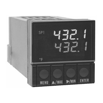
Page 15: Front Panel View
part ETUP 2.2. Front Panel View Front Panel Annunciators OUT1/Setpoint 1 indicator. OUT2/Setpoint 2 indicator. Alarm 1 indicator. Alarm 2 indicator. ¡C ¡C unit indicator. ¡F ¡F unit indicator. Upper display shows the Process Value Lower display shows the Setpoint Value MENU Changes display to Configuration Mode and advances thru menu items* Figure 2.2 Front Panel Display... -
Page 16: Rear Panel View
part ETUP 2.3. Rear Panel View Figure 2.3 Typical Rear Connector Label and Possible Labels of Different Models... -
Page 17: Rear Panel Connector Labels
part ETUP Rear Panel Connector Labels POWER AC Power Connector: All models INPUT Input Connector: All models TC, PR (Process) ALARM 1 ALARM 1 relay SPST, programmable: All models OUTPUT 1 Control Output 1: Based on one of the following models. Relay SPDT Voltage and Current Solid State Relay... -
Page 18: Mechanical Installation
part ETUP 2.4. Mechanical Installation The settings of the DIP switch must be verified or set to comply with your Dip Switch selection at the Input/Type menu (see Section 3.0 for Input/Type). The DIP Configuration switch is accessible through an opening on the side of the case. After carefully removing the controller from the case, see Section 2.1 for instructions, locate the dip switch (see Figure 2.4) and set the switches according to the following tables. -
Page 19: Dip Switch Settings
part ETUP Dip Switch Settings... -
Page 20: Electrical Installation
part ETUP 2.5. Electrical Installation POWER CONNECTION EXAMPLES The figure below shows the power wiring hookup. Use copper conductors only for power connections The Protective Conductor terminal must be connected for safety reasons. Fuse Connector Output Type 115 Vac 230 Vac Fuse 1 Output 1 Relay... -
Page 21: Input Connection Examples
part ETUP INPUT CONNECTION EXAMPLES The figure below shows the wiring hookup for any thermocouple type. For 2.5.1. Thermocouple example, for Type K hookup, connect the yellow wire to the + (+S) Terminal and the red wire to the Ð (ÐS) Terminal. When configuring your controller, select Thermocouple and Thermocouple type in the Input Type menu (see part 3). -
Page 22: Two/Three/Four Wire Rtd
part ETUP The figures below show the input connections and input connector jumpers 2.5.2. Two/Three/Four-Wire RTD required to hookup a 2, 3 or 4-wire RTD. The two-wire connection is the simplest method, but does not compensate for lead- wire temperature change and often requires calibration to cancel lead-wire resistance offset. -
Page 23: Process Current
part ETUP 2.5.3. Process Current The figure shows the wiring hookup for Process Current 0 - 20 mA. When configuring your controller, select Process type in the Input Type menu (see part 3). Figure 2.5.4 Process Current Wiring Hookup 2.5.4. Process Voltage The figure shows the wiring hookup for Process Voltage 0 - .1 V, 0 - 1 V, or 0 -10 V. -
Page 24: Introduction
part PERATION ONFIGURATION 3.1 Introduction The Controller has two different modes of operation. The first, Run Mode, is used to display values for the process variable, setpoint value and to display or clear peak and valley values. The other mode, Menu Configuration Mode, is used to navigate through the menu options and configure the controller. -
Page 25: Function In Configuration Mode
part PERATION ONFIGURATION Button Function in Configuration Mode MENU To enter the Configuration Mode, the user must first press MENU. Use this button to advance/navigate to the next setting. The first menu to appear will be "ID Code", if enabled. The user can navigate through all the top level menus by pressing MENU. -
Page 26: Menu Configuration
part PERATION ONFIGURATION 3.2 Menu Configuration: Modifying set points will not reset the controller Figure 3.1 Flowchart for ID and Set Point Menus... -
Page 27: Id Number
part PERATION ONFIGURATION ID Number (if enabled) It is recommended that you put the controller in the Standby Mode Note for any configuration change other than setpoints & alarms Display Action Response SEE ID OPTION SUBMENU IN THE BREAK LOOP ALARM SECTION FOR ENABLE/DISABLE ID OPTION ENTERING OR CHANGING YOUR (NON-DEFAULT) ID NUMBER Press MENU Press MENU, if necessary, until "ID C0DE"... -
Page 28: Set Points
part PERATION ONFIGURATION Set Points (if ID Number Enabled) Display Action Response SETPOINT 1 " " Press MENU Press MENU, if necessary, until SET PT prompt appears. " " Press ENTER Display advances to , Setpoint 1. DISPLAY SHOWS PREVIOUS VALUE. 1ST DIGIT FLASHING. Press MAX Press MAX to increase digit 0-9. - Page 29 part PERATION ONFIGURATION Setpoints cont. Display Action Response OUTPUT REDIRECTION: DISPLAY SHOWS ÒS1. o . 1 Ó AND CURRENT SETTING, ÒS1. o . 1 Ó S1. o . 1 OR ÒS1. o . 2 Ó S1. o . 1 When ÒS1. o . 1 Ó is selected, Setpoint 1 (and OUT 1 configuration) direct the control output at label ÒOutput 1Ó...
- Page 30 part PERATION ONFIGURATION Set Points (if ID Number Disabled - default) Display Action Response With ID number disabled and in Run Mode, pressing MENU one time advances the controller to Setpoint 1 setting directly. SET POINT 1 Press MENU 1) Press MENU once from Run Mode. 125.
- Page 31 part PERATION ONFIGURATION Figure 3.2 Flowchart for Input Type...
-
Page 32: Input Type (Thermocouple)
part PERATION ONFIGURATION Input Type (Thermocouple) Display Action Response ENTER INPUT TYPE MENU: INPT " " Press MENU Press MENU, if necessary, until Inpt type prompt appears. TYPE " " " " " " Press ENTER Display flashes t. c , or proc (RTD, Thermocouple, Process), if the... -
Page 33: Input Type (Rtd)
part PERATION ONFIGURATION Input Type (RTD) Display Action Response ENTER INPUT TYPE MENU: INPT " " Press MENU Press MENU, if necessary, until Inpt type prompt appears. TYPE " " " " " " Press ENTER Display flashes t. c , or proc (RTD, Thermocouple, Process), if the... -
Page 34: Input Type (Rtd Value)
part PERATION ONFIGURATION Input Type (RTD Value) Display Action Response RTD VALUE SUBMENU: " " Press ENTER Press ENTER at rtd valU prompt to enter your RTD Value. Display flashes VALU previous RTD value selection ie. 100 _ (see below for RTD value selections) Press MAX Scroll through the available RTD Values to the selection of your choice: 100 _... -
Page 35: Input Type (Process)
part PERATION ONFIGURATION Input Type (Process) Display Action Response ENTER INPUT TYPE MENU: INPT " " Press MENU Press MENU, if necessary, until Inpt type prompt appears. TYPE " " " " " " Press ENTER Display flashes t. c , or proc (RTD, Thermocouple, Process), if the... - Page 36 part PERATION ONFIGURATION Figure 3.3 Flowchart for Reading Configuration...
-
Page 37: Reading Configuration
part PERATION ONFIGURATION Reading Configuration Display Action Response " " Press MENU Press MENU, if necessary, until Reading Configuration prompt appears. CNFG " " Press ENTER Display advances to deC. pt (Decimal Point). DECIMAL POINT SUBMENU: DEC. Press ENTER Display flashes previous selection for decimal location. Press MAX Scroll though the available selections and choose decimal location: FFFF. - Page 38 part PERATION ONFIGURATION Reading Configuration cont. Display Action Response FILTER CONSTANT SUBMENU: fltr Press ENTER 9) Display flashes previous selection for filter constant. Cnst Press MAX 10) Scroll though the available selections: 0001, 0002, 0004, 0008, 0016, 0032, 0064, 0128. - Default is 0004 FLTR "...
- Page 39 part PERATION ONFIGURATION Reading Configuration cont. (If process was selected) Display Action Response INPUT SCALE & OFFSET SUBMENU: INPT S C . 0 F " " " " Press ENTER 12) Press enter at the INPT prompt. Display flashes 1st digit in submenu IN 1 SC.
- Page 40 part PERATION ONFIGURATION Modifying Alarm settings will not reset the controller Figure 3.4 Flowchart for Alarm 1 and Alarm 2...
-
Page 41: Alarm
part PERATION ONFIGURATION Alarm 1 Display Action Response ALAR " " Alar 1 Press MENU 1) Press MENU, if necessary, until prompt appears. " " " " Press ENTER 2) Display advances to Alar. 1 enbl dsbl submenu. ALARM 1 ENABLE/DISABLE SUBMENU: ALR. - Page 42 part PERATION ONFIGURATION Alarm 1 cont. Display Action Response ALARM LATCHED OR UNLATCHED SUBMENU: ALR. 1 Press MAX 7) Display flashes previous selection. Press MAX to Latched or Unlatched. LTCH " " " " Press ENTER 8) Display flashes strd message and advances to Contact Closure submenu.
- Page 43 part PERATION ONFIGURATION Alarm 1 cont. Display Action Response ALARMS ENABLE/DISABLE AT POWER ON: A. P . o N Press MAX 11) Display flashes previous selection. Press MAX to enable or disable. ENBL If the alarm is enabled at Power On, the alarm will be active right after reset. If the alarm is Note disabled at Power On, the alarm will become enabled when the process value enters the non alarm area.
-
Page 44: Alarm
part PERATION ONFIGURATION Alarm 2 Display Action Response ALAR " " Press MENU 1) Press MENU, if necessary, until Alar 2 display appears. " " Press ENTER 2) Display advances to Alarm 2 Enable/Disable submenu. " " IF ALARM 2 IS NOT INSTALLED, THE CONTROLLER WILL SHOW NOT INSTALLED NoT _ "... - Page 45 part PERATION ONFIGURATION Figure 3.5 Flowchart for Loop Break...
-
Page 46: Loop Break Alarm
part PERATION ONFIGURATION Loop Break Alarm Display Action Response L00P " " Press MENU 1) Press MENU, if necessary, until the Loop Break prompt appears. BR. A L " " Press ENTER 2) Display advances to Loop Break Enable/Disable submenu. LOOP BREAK ENABLE/DISABLE SUBMENU: L. - Page 47 part PERATION ONFIGURATION Loop Break Alarm cont. Display Action Response LOOP BREAK ALARM VALUE SUBMENU: L. B . A L Press ENTER 6) Display flashes 1st digit of previous loop value. " " Press MAX & MIN 7) Press MAX and MIN buttons to enter a new Loop Value 00.
- Page 48 part PERATION ONFIGURATION Loop Break Alarm cont. Display Action Response ID CODE OPTION SUBMENU 12) Display flashes current status of ID Option, enabled or disabled. Press MAX 13) Press MAX button to select between Enable and Disable. Press ENTER 14) Display flashes ÒstrdÓ and advances to ÒOutput 1.Ó DSBL With ID Code Option disabled, the ID Number submenu is hidden.
- Page 49 part PERATION ONFIGURATION Figure 3.6 Flowchart for Output 1...
-
Page 50: Output 1
part PERATION ONFIGURATION Output 1 Display Action Response " " Press MENU 1) Press MENU, if necessary, until the out 1 prompt appears. Press ENTER 2) Display advances to ÒSelfÓ submenu. SELF SUBMENU The Self Option allows the output of the controller to be controlled manually from the front panel. SELF 3) Display flashes the current setting of Self, enabled or disabled. - Page 51 part PERATION ONFIGURATION Output 1 cont. Display Action Response MAXIMUM/PERCENT HIGH SUBMENU Specify in percent, the maximum value (0099) for control output. If the output is analog, then the maximum voltage or current, in percent, is specified. If the output is time proportional, then the maximum duty-cycle, in percent, is specified.
- Page 52 part PERATION ONFIGURATION Output 1 cont. Display Action Response 4-20 If Current/Voltage is your analog control output 1, this menu i.e. ctrL type will not appear, instead 4-20/Curr will be CURR " " " " displayed. Select Enbl for a 4-20 mA (2-10 V) output or dsbl for a 0-20 mA (0-10 V) output.
- Page 53 part PERATION ONFIGURATION Output 1 cont. Display Action Response AUTO PID SUBMENU: AUTO " " " " enbl dsbl Press ENTER 19) Display flashes Press MAX 20) Scroll through the available selections: Enable or Disable. " " Enabled , the controller can determine, by enabling Start PID, the optimum values AUTO for the three adjustments Ñ...
- Page 54 part PERATION ONFIGURATION Output 1 cont. Display Action Response ANTI INTEGRAL SUBMENU: ANT I " " " " Press ENTER 25) Display flashes enbl dsbl I NTG Press MAX 26) Scroll through the available selections: Enable or Disable. " " Enabled , this feature allows the error term outside the proportional band to be ANT I...
- Page 55 part PERATION ONFIGURATION Output 1 cont. Display Action Response " " " " AUTO TUNE PID DISABLED , the display will show the following three submenus so the user may manually enter values for Proportional, Reset and Rate terms corresponding to P, I, and D. It also can be used for auto PID for disabling unwanted parameters e.
- Page 56 part PERATION ONFIGURATION Output 1 cont. Display Action Response CYCLE TIME SUBMENU: CYCL " " Press ENTER 37) Display flashes 1st digit of the previous Cycle Time value. TIME " " Press MAX & MIN 38) Press MAX and MIN buttons to enter a new Cycle Time value.
- Page 57 part PERATION ONFIGURATION Output 1 cont. Display Action Response DAMPING FACTOR SUBMENU: DPNG " " Press ENTER 40) Display flashes the previous Damping Factor selection. FCTR Press MAX 41) Scroll through the available selections: 0000, 0001, 0002, 0003, 0004, 0005, DPNG 0006, 0007, 0008 - Default is 0003.
- Page 58 part PERATION ONFIGURATION Output 1 cont. Display Action Response " " " " Dead Band submenu will only appear if the On/Off was selected from the " " Control Type menu. DEADBAND SUBMENU: DEAD " " Press ENTER 43) Display flashes 1st digit of the previous Dead Band value.
- Page 59 part PERATION ONFIGURATION Figure 3.7 Flowchart for Output 2...
-
Page 60: Output 2
part PERATION ONFIGURATION Output 2 Display Action Response " " Press MENU 1) Press MENU, if necessary, until the out 2 prompt appears. " " Press ENTER 2) Display advances to Control Type submenu. " " IF OUTPUT 2 IS NOT INSTALLED, THE CONTROLLER WILL SHOW NOT INSTALLED NoT _ "... - Page 61 part PERATION ONFIGURATION Output 2 cont. Display Action Response ACTION TYPE SUBMENU: ACTN " " " " drCt rUrs Press ENTER 6) Display flashes TYPE Press MAX 7) Scroll through the available selections: Direct or Reverse. " " " " Press ENTER 8) Display flashes strd...
- Page 62 part PERATION ONFIGURATION Output 2 cont. Display Action Response AUTO PID SUBMENU: AUTO " " " " Press ENTER 9) Display flashes enbl dsbl Press MAX 10) Scroll through the available selections: Enable or Disable. " " Enabled , the PID parameter of Output 1 will be copied to Output 2. AUTO "...
- Page 63 part PERATION ONFIGURATION Output 2 cont. Display Action Response CYCLE TIME SUBMENU: " " Press ENTER 15) Display flashes 1st digit of the previous Cycle Time value. TIME " " Press MAX & MIN 16) Press MAX and MIN buttons to enter a new Cycle Time value.
- Page 64 part PERATION ONFIGURATION Output 2 cont. Display Action Response " " " " Dead Band submenu will only appear if the On/Off was selected from the " " Control Type menu. DEAD BAND SUBMENU: DEAD " " Press ENTER 18) Display flashes 1st digit of the previous Dead Band value.
- Page 65 part PERATION ONFIGURATION Figure 3.8 Flowchart for Ramp & Soak...
-
Page 66: Ramp & Soak
part PERATION ONFIGURATION Ramp & Soak Display Action Response " " RAMp raMp soac Press MENU 1) Press MENU, if necessary, until the prompt appears. " " Press ENTER 2) Display advances to Ramp Enable/Disable submenu. SoAc RAMP ENABLE/DISABLE SUBMENU: RAMp "... - Page 67 part PERATION ONFIGURATION Ramp & Soak cont. Display Action Response RAMP VALUE SUBMENU: RAMp " " Press ENTER 9) Display flashes 1st digit of previous raMp value. 05. 6 7 " " Press MAX & MIN 10) Press MAX and MIN buttons to enter a new raMp value.
-
Page 68: Available Options
part PERATION ONFIGURATION 3.3 Available Options The Controller may be ordered with one of the three following options: 1) Analog Output: This option provides additional flexibility to transmit the equivalent value of process variable to other devices using a 4 to 20 mA current loop or 0-10 V signal. -
Page 69: Analog Output Option
part PERATION ONFIGURATION Analog Output Option Figure 3.9 Flowchart for Analog Output Option... - Page 70 part PERATION ONFIGURATION Analog Output Option cont. Display Action Response ANLG " ANLG OUT " Press MENU 1) Press MENU, if necessary, until the prompt appears. Press ENTER 2) Display advances to "Analog Type" submenu. IF THE ANALOG OUTPUT OPTION IS NOT INSTALLED, THE CONTROLLER WILL NoT _ "...
- Page 71 part PERATION ONFIGURATION Analog Output Option cont. Display Action Response READING 1 RD 1 Press ENTER 6) Display flashes 1st digit of previous ÒReading 1Ó value. 0000 Press MAX & MIN 7) Enter "Reading 1" value. "o " Press ENTER 8) Display advances to OUT 1 UT.
-
Page 72: Communication Option
part PERATION ONFIGURATION Communication Option Figure 3.10 Flowchart for Communication Option... - Page 73 part PERATION ONFIGURATION Communication Option cont. Display Action Response COM7 " COM7 OPTN " Press MENU Press MENU, if necessary, until the prompt appears. OPTN Press ENTER Display advances to ÒCommunication Parameters" submenu. IF THE COMMUNICATION OPTION IS NOT INSTALLED, THE CONTROLLER WILL NoT _ "...
- Page 74 part PERATION ONFIGURATION Communication Option cont. Display Action Response PARITY SUBMENU: PRTY Press ENTER 7) Display flashes previous selection for "Parity". EVEN Press MAX 8) Scroll through the available selections: NO, ODD, EVEN. " strd " " " Press ENTER 9) Display flashes message and advances to Data Bit...
- Page 75 part PERATION ONFIGURATION Communication Option cont. Display Action Response LINE FEED SUBMENU: _ LF _ Press ENTER 14) Display flashes previous selection for "Line Feed". _ No _ Press MAX 15) Scroll through the available selections: NO, YES. " " strd Press ENTER 16) Display flashes...
- Page 76 part PERATION ONFIGURATION Communication Option cont. Display Action Response MODE SUBMENU: MoDE Press ENTER 23) Display flashes previous selection for "Mode". CMD _ Press MAX 24) Scroll through the available selections: CMND, CONT (command, continuous). " " " " Press ENTER 25) Display flashes strd message and advances to...
- Page 77 part PERATION ONFIGURATION Communication Option cont. Display Action Response STATUS SUBMENU: STAT Press ENTER 33) Display flashes previous selection for "Status" (alarm status). _ YES Press MAX 34) Scroll through the available selections: NO, YES. " " Press ENTER 35) Display flashes strd message and advances to "Reading"...
- Page 78 part PERATION ONFIGURATION Communication Option cont. Display Action Response UNIT SUBMENU: UNIT " " Press ENTER 45) Display flashes previous selection for Unit _ YES Press MAX 46) Scroll through the available selections: NO, YES. " " " " Press ENTER 47) Display flashes strd message and advances to...
- Page 79 part PERATION ONFIGURATION Communication Option cont. Display Action Response TRANSMIT TIME SUBMENU: TR. T I " " tr. t i st. u p Display shows prompt. This menu is applicable if Continuous Mode was ST. U P selected. " " Press ENTER 55) Display advances to Transmit Time Value...
-
Page 80: Command Formats
part PERATION ONFIGURATION COMMUNICATION COMMANDS (Table 3.1) Command Prefix Meaning (Command Class) Special read, Communication parameters P (Put) Write HEX data into RAM W (Write) Write HEX data into EEPROM. 1,000,000 writes to EEPROM is guaranteed! G (Get) Read HEX data from RAM R (Read) Read HEX data from EEPROM Read status byte... - Page 81 part PERATION ONFIGURATION Command Formats cont. Where "*" is the selected Recognition Character. You may select any ASCII table symbol from "!" (HEX address "21") to the right-hand brace (HEX "7D") except for the caret "^", "A", "E", which are reserved for bus format request. "(nn)" are the two ASCII characters for the device Bus Address.
- Page 82 part PERATION ONFIGURATION Command Formats cont. Description: SETPOINT.23 ~ 0 means 3 bytes x 8 bit positions (2 characters in each byte). SETPOINT.23 = 0 = positive sign SETPOINT.22~20 = 000 - Not Allowed SETPOINT.19~0 = Setpoint data 1 = negative sign 001 - Decimal Point 1 (XXXX.) 010 - Decimal Point 1 (XXX.X) 011 - Decimal Point 1 (XX.XX)
- Page 83 part PERATION ONFIGURATION Command Formats cont. Note No spaces are allowed in the data string. The spaces provided in the previous example are for illustration purposes only. Note Decimal Point position for TC/RTD = 1 or 2, for PROCESS = 1, 2 , 3, or 4. Decimal Point position for setpoint should be the same as Decimal Point position sets for Process Value and can not be Note overwritten by SETPOINT command.
- Page 84 part PERATION ONFIGURATION COMMAND LETTERS AND INDEX (Table 3.2) Command Command Function Command Default Index Bytes Characters Value 200000 200000 GPRW RDGOFF 200000 0000 INPUT GPRW RDGCNF AL1CNFG LOOP BREAK TIME 003B OUT1CNF OUT2CNF RAMPTIME 0000 COMM.PARAMETERS AL1LO A003E8 AL1HI 201170 GPRW RDGSCL...
- Page 85 part PERATION ONFIGURATION COMMAND LETTERS AND INDEX cont. COMMAND LETTERS AND INDEX cont. Command Command Function Command Default Command Command Function Index Bytes Characters Value Index GPRW PB1/DEAD BAND 00C8 DISABLE ALARM 1 GPRW RESET 1 00B4 STANDBY GPRW RATE 1 0000 DISABLE SELF GPRW...
- Page 86 part PERATION ONFIGURATION Command Formats Description: INPUT.76543210 means 8 bit positions of the Input Command Data (Operand). INPUT.76 = 00 = 100 ohm RTD INPUT.5432 = 0000 J/392-2/0-100 mV INPUT.10 = 00 TC 01 = 500 ohm RTD 0001 K/392-3/0-1 V 01 RTD 10 = 1000 ohm 0010...
- Page 87 part PERATION ONFIGURATION Command Formats cont. RDGCNF.210 = 000 Not Allowed RDGCNFG.3 = 0 ¡C RDGCNFG.765 = 000 Filter constant 1 001 Decimal Point 1 (XXXX.) 1 ¡F 001 Filter constant 2 010 Decimal Point 2 (XXX.X) 010 Filter constant 4 011 Decimal Point 3* (XX.XX) 011 Filter constant 8 100 Decimal Point 4* (X.XXX)
- Page 88 part PERATION ONFIGURATION Command Formats cont. AL1CNFG.0 = 0 Disable AL1CNFG.1 = 0 Absolute AL1CNFG.2 = 0 Unlatch AL1CNFG.3 = 0 Normally Open 1 Enable 1 Deviation 1 Latch 1 Normally Closed AL1CNFG.54 = 00 Above AL1CNFG.6 = 0 Loop Break Alarm Disable AL1CNFG.7 = 0 Alarm Power On Enable 01 Below 1 Loop Break Alarm Enable...
- Page 89 part PERATION ONFIGURATION Command Formats cont. Time Proportional: OUT1CNFG.0 = 0 On/off Analog Proportional: OUT1CNFG.6 = 0 0 - 20 mA 1 PID 1 4 - 20 mA OUT1CNFG.1 = 0 Reverse OUT1CNFG.2 = 0 Auto PID Disable OUT1CNFG.3 = 0 Adaptive Disable 1 Direct 1 Auto PID Enable 1 Adaptive Enable...
- Page 90 part PERATION ONFIGURATION Command Formats cont. OUT2CNFG.0 = 0 On/off OUT2CNFG.1 = 0 Reverse OUT2CNFG.2 = 0 Manual PID 1 PID 1 Direct 1 Auto PID OUT2CNFG.3 = 0 Ramp Disable OUT2CNFG.4 = 0 Soak Disable OUT2CNFG.765 = 000 Damping 1 1 Ramp Enable 1 Soak Enable 001 Damping 2...
- Page 91 part PERATION ONFIGURATION Command Formats cont. COMM.PARAMETERS.210 = 000 BAUD COMM. PARAMETERS.43 = 00 No Parity 01 Odd 1200 10 Even 2400 11 N/A 4800 9600 110 19200 COMM. PARAMETERS.5 = 0 7 Bit Data COMM. PARAMETERS.6 = 0 1 Stop Bit 8 Bit Data 2 Stop Bit Example: Set Baud 9600, Odd, 7 Bit, 1 Stop.
- Page 92 part PERATION ONFIGURATION Command Formats cont. Note DATAFORMAT is used for V01 command or Continuous Mode (RS-232). DATAFORMAT.0 = 0 No Status DATAFORMAT.1 = 0 No Reading DATAFORMAT.2 = 0 No Peak 1 Alarm Status 1 Reading 1 Peak DATAFORMAT.3 = 0 No Valley DATAFORMAT.6 = 0 No Unit DATAFORMAT.7 = N/A 1 Valley...
- Page 93 part PERATION ONFIGURATION Command Formats cont. RDGOFF.0~19 = Offset Data RDGOFF.20~22 = DP+2 RDGOFF.23 = 0 Positive Offset 1 Negative Offset RDGSC.0~18 = Scale Data RDGSC.19 = 0 Direct Scale RDGSC.20~23 = DP+1 1 Reverse Scale Example: To have an input of 4 to 20 mA displayed as 0 to 100, The Low input value = min.
-
Page 94: Reading Scale
part PERATION ONFIGURATION Reading Scale Scale = (UD - LD)/(UI -LI), where: UD - Upper Display, LD - Low Display UI - Upper Input, LI - Low Input Scale = (100 - 0)/(9999-2000) = 0.0125016 (These values were obtained from example on previous Section 3: Reading Configuration with Process) 0.0125016 = 125016 x 10^ -7, where 125016 is Reading Scale Data, Decimal Point = 7 RDGSC.23~20 = 8 (DP = 7);... -
Page 95: Reading Offset
part PERATION ONFIGURATION Reading Offset Offset = UD - Scale x UI Offset = 100 - (0.0125) x (10000) = (-25), where Offset data = 25, Decimal Point = 0, Offset is negative. RDGOFF.23 = 1 (Offset is negative); RDGOFF.22 ~ 20 = 2 (DP = 0); RDGOFF.19 ~ 0 = 00019Hex (25 Dec) Binary Code: Hex. -
Page 96: Remote Setpoint Option
part PERATION ONFIGURATION Remote Setpoint Option Figure 3.11 Flowchart for Remote Setpoint... - Page 97 part PERATION ONFIGURATION Remote Setpoint Option cont. Display Action Response R. S ET " " r. s et p0nt Press MENU Press MENU, if necessary, until the prompt appears. p0nt " " Press ENTER Display advances to Remote Setpoint 1 submenu.
- Page 98 part PERATION ONFIGURATION Remote Setpoint Option cont. Display Action Response REMOTE SETPOINT 3 SUBMENU: R. S P. 3 " " Press ENTER Display flashes 1st digit of previous selection for Remote Setpoint 3 value. 275. 0 " " Press MAX & MIN Enter a new Remote Setpoint 3 value.
- Page 99 part PECIFICATIONS CONTR R OL Accuracy: See the following Specification Chart. Resolution: 1¡/0.1¡; 10 µV process Action: Reverse (heat) or direct (cool) Temperature Stability: 0.08¡C/¡C; 50 ppm/¡C process Modes: Time proportioning and proportional control modes; selectable preset tune, adaptive tune, auto-tune, PID, proportional, proportional with integral, proportional Thermocouple Cold End Tracking: 0.05¡C/¡C with derivative with anti-reset windup, on-off NMRR: 60 dB...
- Page 100 part PECIFICATIONS G G E E N N E E R R A A L L : : C C O O M M M M U U N N I I C C A A T T I I O O N N S S : : Line Voltage: 90-240 Vac +/-10%, 50-400 Hz RS-232 or RS-485: 300 to 19.2k baud;...
- Page 101 part PECIFICATIONS Input Input Type Range Accuracy* Type Range Accuracy* Iron- -210 to 760°C 0.4°C 5%Re-W/ 0-2354°C 0.4°C Constantan -346 to 1400°F 0.7°F 26%Re-W 32-4253°F 0.7°F -270 to -160°C 1.0°C -250 to -100°C 1.0°C CHROMEGA ® -160 to 1372°C 0.4°C Nicrosil- -100 to 1300°C 0.4°C...
- Page 102 CE APPROVAL INFORMATION 1. Electromagnetic Compatibility (EMC) This instrument complies with the following EMC Emission Standards This device comforms with requirements of EMC Directive 89/336/EEC, as tested per EN 50081-1, 1992 (Residential, Commercial and Light amended by 93/68/EEC. This instrument complies with the following Industrial) EMC Immunity Standards as tested per EN 50082-2, 1995 (Industrial environment)
- Page 103 If the unit should malfunction, it must be returned to the factory for evaluation. OMEGAÕs Customer Service Department will issue an Authorized Return (AR) number immediately upon phone or written request. Upon examination by OMEGA, if the unit is found to be defective it will be repaired or replaced at no charge. However, this WARRANTY is VOID if the unit shows evidence of having been tampered with or shows evidence of being damaged as a result of excessive corrosion;...
- Page 104 Where Do I Find Everything I Need for Process Measurement and Control? OMEGA…Of Course! Shop on line at www.omega.com DATA ACQUISITION TEMPERATURE Data Acquisition & Engineering Software Thermocouple, RTD & thermistor Probes, Connectors, Communications-Based Acquisition Systems Panels & Assemblies Plug-in Cards for Apple, IBM & Compatibles Wire: Thermocouple, RTD &...
Need help?
Do you have a question about the MICROMEGA CN77000 series and is the answer not in the manual?
Questions and answers