
Subscribe to Our Youtube Channel
Related Manuals for Teledyne JCU-3


Summary of Contents for Teledyne JCU-3
- Page 1 JCU-3 INSTALLATION & OPERATION INSTRUCTIONS English (en-US) Date: 01-2023 Document number: 71002 (Rev 2) © 2023 Teledyne FLIR LLC...
- Page 3 Trademark and patents notice Raymarine, Tacktick, Clear Pulse, Truzoom, SeaTalk, SeaTalk , SeaTalkng, and Micronet, are registered or claimed trademarks of Raymarine Belgium. FLIR, YachtSense, DockSense, LightHouse, RangeFusion, DownVision, SideVision, RealVision, HyperVision, Dragonfly, Element, Quantum, Axiom, Instalert, Infrared Everywhere, The World’s Sixth Sense and ClearCruise are registered or claimed trademarks of FLIR Systems, Inc. All other trademarks, trade names, or company names referenced herein are used for identification only and are the property of their respective owners.
-
Page 5: Table Of Contents
Product overview ............13 Keypad network connections ........29 Compatibility ............... 13 Single JCU-3 keypad with single camera and CHAPTER 4 PARTS SUPPLIED........14 laptop web browser ..........29 Parts supplied ............. 15 Single JCU-3 keypad with single camera and CHAPTER 5 PRODUCT DIMENSIONS....... - Page 6 CHAPTER 10 POWER CONNECTIONS ..... 31 Conformance specification 14.4 ........47 Positive ground systems 10.1 ........32 CHAPTER 15 TECHNICAL SUPPORT......48 Alternate power connection 10.2 ........32 FLIR Maritime product support and 15.1 Inline fuse and thermal breaker ratings 10.3 ....
-
Page 7: Chapter 1 Important Information
CHAPTER 1: IMPORTANT Warning: Potential ignition source INFORMATION This product is NOT approved for use in hazardous/flammable atmospheres. Do NOT install in a hazardous/flammable atmosphere (such as in an engine room or near fuel tanks). Safety warnings Caution: Power supply protection When installing this product ensure the power source is Warning: Product installation and operation adequately protected by means of a suitably-rated fuse or... -
Page 8: Declaration Of Conformity
Product disposal Note: Dispose of this product in accordance with the WEEE Directive. In areas of extreme EMC interference, some slight interference may be The Waste Electrical and Electronic Equipment (WEEE) Directive requires noticed on the product. Where this occurs the product and the source of the recycling of waste electrical and electronic equipment which contains the interference should be separated by a greater distance. -
Page 9: Publication Copyright
Publication copyright Copyright © 2023 Teledyne FLIR LLC. All rights reserved. No parts of this material may be copied, translated, or transmitted (in any medium) without the prior written permission of Teledyne FLIR LLC. -
Page 10: Chapter 2 Document Information
CHAPTER 2: DOCUMENT INFORMATION CHAPTER CONTENTS • 2.1 Document information — page 11 • 2.2 Document illustrations — page 11 • 2.3 Product documentation — page 11... -
Page 11: Document Information
All images are provided for illustration purposes only. 2.3 Product documentation The following documentation is applicable to your product: Description Part number JCU-3 Installation and operation instructions (this 71002 doccument) JCU-3 Mounting template 87283 Document information... -
Page 12: Chapter 3 Product And System Overview
CHAPTER 3: PRODUCT AND SYSTEM OVERVIEW CHAPTER CONTENTS • 3.1 Product overview — page 13 • 3.2 Compatibility — page 13... -
Page 13: Product Overview
3.1 Product overview 3.2 Compatibility The JCU-3 is a remote keypad for FLIR thermal cameras. The keypad is a The JCU-3 keypad is compatible with the following FLIR thermal cameras: class 1 PoE (Power over Ethernet) device and can be powered either using •... -
Page 14: Chapter 4 Parts Supplied
CHAPTER 4: PARTS SUPPLIED CHAPTER CONTENTS • 4.1 Parts supplied — page 15... -
Page 15: Parts Supplied
4.1 Parts supplied The parts supplied with the keypad are shown below. Item Description JCU-3 keypad Landscape keypad mat Portrait keypad mat (supplied fitted to the unit) Mounting gasket 4 x mounting fixings Documentation pack Right angled power cable 2 m (6.6 ft.) RayNet network cable 2 m (6.6 ft.) -
Page 16: Chapter 5 Product Dimensions
CHAPTER 5: PRODUCT DIMENSIONS CHAPTER CONTENTS • 5.1 Product dimensions — page 17... -
Page 17: Product Dimensions
5.1 Product dimensions Item Dimension 34.8 mm (1.37 in) 10.5 mm (0.41 in) 28.4 mm (1.12 in.) 31.7 mm (1.25 in.) 50.7 mm (2.00 in.) 80.0 mm (3.15 in.) 119.0 mm (4.69 in.) 133.0 mm (5.24 in.) 41.0 mm (1.61 in.) 55.0 mm (2.17 in.) Product dimensions... -
Page 18: Chapter 6 Location Requirements
CHAPTER 6: LOCATION REQUIREMENTS CHAPTER CONTENTS • 6.1 Warnings and cautions — page 19 • 6.2 General location requirements — page 19 • 6.3 Compass safe distance — page 19... -
Page 19: Warnings And Cautions
6.1 Warnings and cautions motors, generators, radio transmitters / receivers and cables carrying high power. Important: • Magnetic compass — refer to the Compass safe distance section in this document for advice on maintaining a suitable distance between this Before proceeding, ensure that you have read and understood the product and any compasses on your vessel. -
Page 20: Chapter 7 Cables And Connections - General Information
CHAPTER 7: CABLES AND CONNECTIONS — GENERAL INFORMATION CHAPTER CONTENTS • 7.1 Cable types and length — page 21 • 7.2 Cable routing — page 21 • 7.3 Strain relief — page 21 • 7.4 Cable shielding — page 21 •... -
Page 21: Cable Types And Length
7.1 Cable types and length • Do NOT run cables near to engines or fluorescent lights. • Always route data cables as far away as possible from: It is important to use cables of the appropriate type and length. – Other equipment and cables. •... -
Page 22: Connections Overview
7.6 Connections overview 1. Alternate power connector 2. Network / PoE connector The alternate power connector is required when connecting to a network which does not support Power over Ethernet PoE. The alternate power connector must be connected directly to a power supply. Note: Do not connect the alternate power connector to a SeaTalk network. -
Page 23: Chapter 8 Mounting
CHAPTER 8: MOUNTING CHAPTER CONTENTS • 8.1 Tools required — page 24 • 8.2 Removing the keypad mat — page 24 • 8.3 Flush mounting the keypad — page 25 • 8.4 Surface mounting the keypad — page 26 • 8.5 Fitting the keypad mat —... -
Page 24: Tools Required
8.1 Tools required 8.2 Removing the keypad mat Product installation requires the following tools: To gain access to the mounting hole locations, the keypad mat must be removed. 1. Power drill 2. Pozidrive screwdriver 3. Drill bit Note: Note: To help prevent scratching the product, cover the tip of your screwdriver blade with a small piece of insulation tape. -
Page 25: Flush Mounting The Keypad
8.3 Flush mounting the keypad 8. Ensure that the unit fits into the removed area and then remove rough edges. Flush mounting provides a sleek installation where the product and dash are 9. Place the supplied gasket onto the rear of the keypad, ensuring the mounting holes are aligned. -
Page 26: Surface Mounting The Keypad
8.4 Surface mounting the keypad 10. Secure using the fixings provided. Note: Surface mounting provides a uniform installation where the products protrude, usually by the thickness of the bezel, from the mounting surface. The appropriate tightening torque and drill bit size to use depends on the thickness of the mounting surface and the type of material it is made from. -
Page 27: Fitting The Keypad Mat
8.5 Fitting the keypad mat 3. Close the opposite end of the keypad mat into the keypad, ensuring that the tab slides into the notch provided. Push all of the tabs on the longer sides into their notches (you should hear a click as each tab engages). Your keypad can be installed in portrait or landscape orientation. -
Page 28: Chapter 9 Network Connections
CHAPTER 9: NETWORK CONNECTIONS CHAPTER CONTENTS • 9.1 Keypad network connections — page 29... -
Page 29: Keypad Network Connections
9.1 Keypad network connections Single JCU-3 keypad with single camera and laptop web browser Your keypad must be connected to the same network as your thermal camera, via a network switch. If the network connection to the keypad does not provide Power over Ethernet (PoE), then you must power the keypad using the Alternate power connector. -
Page 30: Single Jcu-3 Keypad With Single Camera And Analog Video Monitor
RayNet (Ethernet) to RJ45 cable process is complete. PoE injector (provides power to JCU-3) Item Description Single JCU-3 keypad with single camera and analog M100 / M200–Series camera video monitor Analog video monitor Joystick control unit (JCU-3) Ethernet network switch... -
Page 31: Chapter 10 Power Connections
CHAPTER 10: POWER CONNECTIONS CHAPTER CONTENTS • 10.1 Positive ground systems — page 32 • 10.2 Alternate power connection — page 32 • 10.3 Inline fuse and thermal breaker ratings — page 32 • 10.4 Power distribution — page 32 •... -
Page 32: Positive Ground Systems
10.1 Positive ground systems Note: • The suitable fuse rating for the thermal breaker is dependent on the Do not connect this unit to a system which has positive grounding. number of devices you are connecting. If in doubt consult an authorized FLIR dealer. - Page 33 individual inline fuses for each power circuit to provide the necessary Important: protection. • When planning and wiring, take into consideration other products in your • The power cable supplied with your product includes a drain wire, which system, some of which (e.g. sonar modules) may place large power must be connected to the vessel’s common RF ground.
-
Page 34: Systems)
Implementation — direct connection to battery Suitable for a vessel with a common RF ground point. In this scenario, the power cable’s drain wire should be connected to the vessel’s common • Where connection to a power distribution panel is not possible, the power ground point. -
Page 35: Power Cable Drain Wire Connection
• Negative grounded (“bonded”), with the negative battery terminal Cable length in Wire gauge in AWG Wire gauge in AWG connected to the vessel's RF ground. meters (feet) ) for 12 V supply ) for 24 V supply • Floating, with neither battery terminal connected to the vessel's ground. 24 (75) 14 (2.08 mm 16 (1.31 mm... -
Page 36: Chapter 11 Operation
CHAPTER 11: OPERATION CHAPTER CONTENTS • 11.1 JCU–3 controls overview — page 37 • 11.2 Pairing the keypad — page 39 • 11.3 Resetting the keypad to factory defaults — page 40... -
Page 37: Jcu-3 Controls Overview
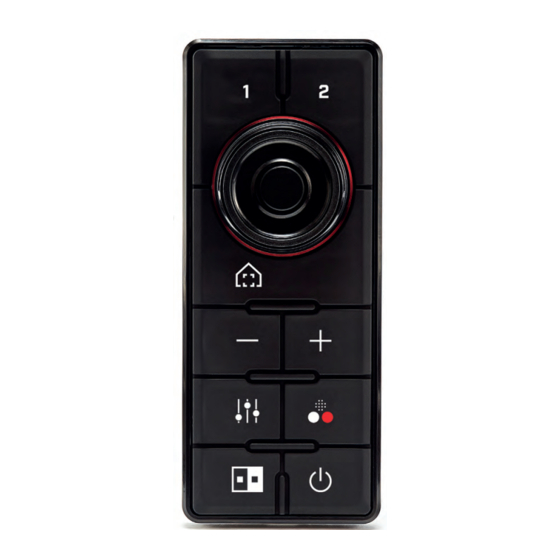
11.1 JCU–3 controls overview Item Description 3, 4, 5 [UNI-CONTROLLER] – Use the uni-controller to control the camera: • Press ring (4) up, down left right – Pan / Tilt camera (pan available on M200–Series only). • Rotate outer ring (3) clockwise or counter-clockwise to pan the camera (pan available on M200–Series only). -
Page 38: Jcu-3 Controls: Notes
The login screen with a picture of the JCU-3 is displayed. JCU–3 controls: notes Note: The listed button actions are the default actions for a JCU-3 keypad controlling an M100/M200 Series thermal camera. Note: You can change the default actions of certain buttons and controls for M100/M200 Series cameras (including the user programmable buttons) using the camera’s web interface. -
Page 39: Pairing The Keypad
11.2 Pairing the keypad 4. Enter “user” for Username and “user” for Password, then click [Login]. Each JCU-3 keypad can be paired with multiple thermal cameras, and each The JCU configuration page is displayed. thermal camera can be paired to multiple keypads. -
Page 40: Resetting The Keypad To Factory Defaults
5. In the left-hand menu, click CAMERAS. list, to confirm that you can control the camera with the JCU-3 keypad. In the [camera connect] list, highlight the camera you want to connect The camera pairing page is displayed. to and click [Select] The JCU-3 keypad connects to the camera;... -
Page 41: Chapter 12 System Checks And Troubleshooting
CHAPTER 12: SYSTEM CHECKS AND TROUBLESHOOTING CHAPTER CONTENTS • 12.1 Keypad status — page 42 • 12.2 PoE troubleshooting — page 42 • 12.3 Power up troubleshooting — page 42 System checks and troubleshooting... -
Page 42: Keypad Status
12.1 Keypad status 12.2 PoE troubleshooting The keypad is backlit with LEDs. The LEDs are used to identify the status of If you are experiencing connection issues with the remote keypad when the keypad. powering the device via PoE, consider using the keypad’s dedicated power connector to supply the power to the device. - Page 43 Possible causes Possible solutions Possible causes Possible solutions Blown fuse / tripped 1. Check condition of relevant fuses and breakers Power supply and See possible solutions from ‘Products does not turn breaker and connections, replace if necessary (Refer connection on or keeps turning off’ above. to the Technical Specification section of your Software corruption 1.
-
Page 44: Chapter 13 Maintenance
CHAPTER 13: MAINTENANCE CHAPTER CONTENTS • 13.1 Service and maintenance — page 45 • 13.2 Routine equipment checks — page 45 • 13.3 Product cleaning — page 45... -
Page 45: Service And Maintenance
13.1 Service and maintenance This product contains no user serviceable components. Please refer all maintenance and repair to authorized FLIR dealers. Unauthorized repair may affect your warranty. 13.2 Routine equipment checks It is recommended that you perform the following routine checks, on a regular basis, to ensure the correct and reliable operation of your equipment: •... -
Page 46: Chapter 14 Technical Specification
CHAPTER 14: TECHNICAL SPECIFICATION CHAPTER CONTENTS • 14.1 Power specification — page 47 • 14.2 Environmental specification — page 47 • 14.3 Wired connections — page 47 • 14.4 Conformance specification — page 47... -
Page 47: Conformance Specification
14.1 Power specification 14.4 Conformance specification Specification Specification PoE class: Class 1 Ethernet/PoE: • IEEE 802.3 Nominal supply voltage: • PoE: 48 V dc • IEEE 802.3af (PoE) • Alternate power: 12 V / 24 V dc EMC: • EN60945 Operating voltage range: •... -
Page 48: Chapter 15 Technical Support
CHAPTER 15: TECHNICAL SUPPORT CHAPTER CONTENTS • 15.1 FLIR Maritime product support and servicing — page 49... -
Page 49: Flir Maritime Product Support And
15.1 FLIR Maritime product support and Region Contact details servicing United Kingdom (UK), EMEA, and Telephone: Asia Pacific +44 (0)1329 246 932 FLIR provides a comprehensive product support service, as well as E-mail: warranty, service, and repairs. You can access these services through the FLIR website, telephone, and e-mail. - Page 50 Region Contact details Region Contact details France Telephone: Finland Telephone: +33 (0)1 46 49 72 30 +358 (0)207 619 937 E-mail: E-mail: support.fr@flir.com support.fi@flir.com (FLIR Maritime subsidiary) (FLIR Maritime subsidiary) Germany Telephone: Norway Telephone: +49 (0)40 237 808 0 +47 692 64 600 E-mail: E-mail: support.de@flir.com...
-
Page 51: Power Cable Extension
CHAPTER 16: SPARES AND ACCESSORIES CHAPTER CONTENTS • 16.1 Keypad spares and accessories — page 52 • 16.2 RayNet to RayNet cables and connectors — page 53 • 16.3 RayNet to RJ45, and RJ45 (SeaTalkhs) adapter cables — page 54 Spares and accessories... -
Page 52: Keypad Spares And Accessories
16.1 Keypad spares and accessories Spares: Item Part number Portrait keypad mat spare R70557 Landscape keypad mat spare R70558 Accessories: Item Part number Right angled 2 m (6.6 ft) power cable A06070 Straight 2 m (6.6 ft) power cable A06049... -
Page 53: Raynet To Raynet Cables And Connectors
16.2 RayNet to RayNet cables and connectors 1. Standard RayNet connection cable with a RayNet (female) socket on both ends. 2. Right-angle RayNet connection cable with a straight RayNet (female) socket on one end, and a right-angle RayNet (female) socket on the other end. Suitable for connecting at 90°... - Page 54 16.3 RayNet to RJ45, and RJ45 (SeaTalkhs) adapter cables...
- Page 55 1. Adapter cable with a RayNet (female) socket on one end, and a waterproof (female) RJ45 (SeaTalkhs®) socket on the other end, accepting the following cables with an RJ45 (SeaTalkhs®) waterproof locking (male) plug: • A62245 (1.5 m). • A62246 (15 m). 2.
- Page 57 Best practice ..................34 Interference ................... 19 See also Compass safe distance Backlight ....................42 Box contents, See Parts supplied JCU-3 orientation setting ............... 38 Cable Keypad mat fitting.................. 27 Bend radius..................21 keypad mat removal ................24 Protection................... 21 Routing....................
- Page 58 Cable extension ................. 34 Wired connections ................47 Distribution ..................32 Technical support................... 49 Distribution panel ................33 Tools required ..................24 Grounding ..................34 Troubleshooting..................42 Sharing a breaker ................33 Typical systems ..................29 Power cable extension ................34 Power connection ..................
- Page 60 EUROPE Teledyne FLIR LLC Teledyne FLIR LLC 110 Lowell Road, Marine House, Cartwright Drive Hudson, NH 03051. Fareham, PO15 5RJ United States of America United Kingdom...
Need help?
Do you have a question about the JCU-3 and is the answer not in the manual?
Questions and answers