
Subscribe to Our Youtube Channel
Related Manuals for Teledyne Oldham MX 16


Summary of Contents for Teledyne Oldham MX 16
- Page 1 SER GUIDE MX 16 ANALOG AND DIGITAL CONTROLLER Version Easy Duo NP16EN Revision A.0...
- Page 2 Copyright November 2020 by TELEDYNE OLDHAM SIMTRONICS S.A.S. All rights reserved. The reproduction of all or any section of this document in any form whatsoever without the written permission of TELEDYNE OLDHAM SIMTRONICS S.A.S. is forbidden. The information contained in this manual is accurate to our knowledge.
-
Page 3: Table Of Contents
MX 16 ANALOG AND DIGITAL CONTROLLER USER GUIDE Table of contents General Information ............... 1 User Manual ......................1 Symbols used ....................... 1 Safety Instructions ....................2 Important Information ..................2 Liability Limits ....................... 2 Warranty ........................ 3 General Introduction ..............5 Purpose of the MX 16 controller .............. - Page 4 12 Specific conditions of use and Functional Safety ....51 Specific Conditions of Use ................51 Specific instructions for the prevention of explosions ......51 Connecting detectors other than TELEDYNE OLDHAM SIMTRONICS detectors to the MX 16 controller ........... 53 NP16EN Revision: A.0...
-
Page 5: General Information
The information, technical data, and diagrams contained in this manual are based on the information that is available at a given time. In case of doubt, contact TELEDYNE OLDHAM SIMTRONICS for additional information. The aim of this manual is to supply simple and accurate information to the user... -
Page 6: Safety Instructions
TELEDYNE OLDHAM SIMTRONICS has been informed of such damage. -
Page 7: Warranty
MX 16 ANALOG AND DIGITAL CONTROLLER USER GUIDE Warranty Under normal conditions of use and on return to the factory, parts and workmanship carry a two year warranty, excluding consumables such as backup power supplies, audio and visible alarms, etc. NP16EN Revision: A.0... - Page 8 MX 16 ANALOG AND DIGITAL CONTROLLER USER GUIDE NP16EN Revision: A.0...
-
Page 9: General Introduction
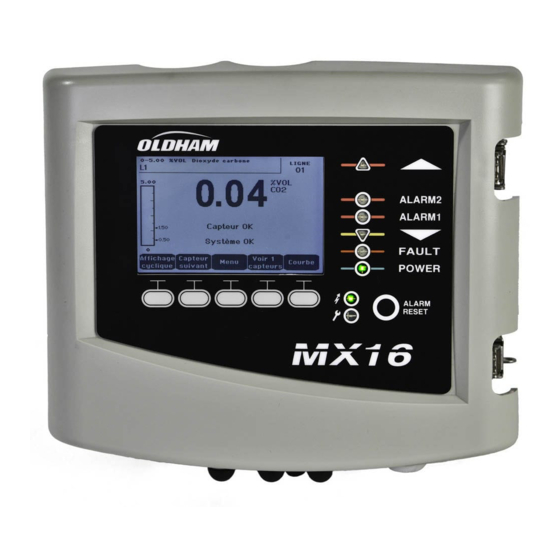
MX 16 ANALOG AND DIGITAL CONTROLLER USER GUIDE 2 General Introduction Purpose of the MX 16 controller This controller is intended for the continuous measurement and control of the gases present in the atmosphere. Figure 1: MX 16 The system primarily comprises: MX 16 controller ■... - Page 10 MX 16 ANALOG AND DIGITAL CONTROLLER USER GUIDE MX 16 Figure 2: Example of an configuration using one analog detector NP16EN Revision: A.0...
-
Page 11: The Different Versions
MX 16 ANALOG AND DIGITAL CONTROLLER USER GUIDE The different Versions MX 16 controller is available in 2 versions: 1 line for digital detector: ■ OLCT10N O2 (0-30% Vol.) OLCT10N CO2 (0-5;00% Vol.) 1 line for 4-20mA analog detector: ■ O2 (0-30% Vol) CO2 (0-5.00% Vol.) CH4 (0-100% LEL) -
Page 12: Firmplate
MX 16 ANALOG AND DIGITAL CONTROLLER USER GUIDE Firmplate 201104Y-693 Firme plate It contains relevant information with respect to the controller version. Tag. Description Part Number Product Name Serial Number. The first four digits (in this case 2007) correspond to the year and the month of manufacture (20 and 07 indicating manufacturing in July 2020) CE marking Electrical characteristics... -
Page 13: Mechanical Installation
MX 16 ANALOG AND DIGITAL CONTROLLER USER GUIDE 3 Mechanical Installation MX 16 Controller Location MX 16 is intended for indoor use only and shall be installed in premises without explosive atmospheres, away from direct exposure to sunlight, and protected from humidity, dust, and temperature variations. - Page 14 Heavy gases are detected close to the ground, while lighter gases are present along the ceiling. If necessary, contact TELEDYNE OLDHAM SIMTRONICS for any questions regarding proper detector positioning.
-
Page 15: The Mx 16 Controller
MX 16 ANALOG AND DIGITAL CONTROLLER USER GUIDE 4 The MX 16 Controller Overview of the Unit External view Figure 6: External view Rep. Function Rep. Function Monochromatic, back-lit graphic Alarm Acknowledgement button LCD display Channel status indicator Failure/maintenance indicator Toggle Latch (one is lockable) Contextual soft keys Power On/Off indicator... - Page 16 MX 16 ANALOG AND DIGITAL CONTROLLER USER GUIDE Internal view Figure 7: Internal view Rep. Function LCD graphic display card Microcontroller reset button. Press this button to reset the controller. CR2032 lithium battery. Allows data and real time clock saving in case of power failure. MX 16 Runtime is approx.
-
Page 17: Front Plate
MX 16 ANALOG AND DIGITAL CONTROLLER USER GUIDE Rep. Function Irregular Irregular Bad communication quality with digital detector. blinking blinking Blinks Communication failure. Absence or failure of digital time detector On communication failure, the internal buzzer, the failure indicator and the Fault relay are activated. No active digital detector is present on the line Grounding terminals to connect cable shield for digital and analog connections From top to bottom, relay alarm terminals (R1 to R2 respectively). - Page 18 MX 16 ANALOG AND DIGITAL CONTROLLER USER GUIDE Figure 9: Display of the measurement (on the left) or parameter settings display (on the right) Menus Refer to paragraph on page 23 for more details about the information that are available on the screen.
- Page 19 MX 16 ANALOG AND DIGITAL CONTROLLER USER GUIDE Icon Function Solid: the gas detector is in alarm condition. Acknowledgment is programmed in automatic mode* or the alarm reset button located on the front panel has already been pushed. *automatic mode acknowledgment is not a standard mode (Consult us) ...
-
Page 20: Alarm Thresholds And Relays
MX 16 ANALOG AND DIGITAL CONTROLLER USER GUIDE Alarm Reset Key (H) Press this key to silence the on-board buzzer and reset the alarms that can be acknowledged. Remote Acknowledgement connector This reset button can be remote, see paragraph on page Alarm Thresholds and Relays MX 16’s Program... - Page 21 MX 16 ANALOG AND DIGITAL CONTROLLER USER GUIDE AL(1,2) Activated if event Solid if event is grayscale mode is still present still present Alarm Reset AL(1,2,3) Deactivated if the OFF if the event is pressed grayscale mode event has disappeared disappeared Alarm Normal mode...
- Page 22 MX 16 ANALOG AND DIGITAL CONTROLLER USER GUIDE NP16EN Revision: A.0...
-
Page 23: Wiring And Electrical Connections
MX 16 ANALOG AND DIGITAL CONTROLLER USER GUIDE 5 Wiring and Electrical Connections This chapter details the electrical connections of all components of the system (MX 16, modules, additional equipment). Controller Connection The electrical connections must be carried out by qualified personnel in compliance with the different directives in force in the country of installation. - Page 24 MX 16 ANALOG AND DIGITAL CONTROLLER USER GUIDE of the building, in the immediate proximity of the MX 16, and be easily accessible to operators. It shall be marked as the cut-off device of the MX 16. The main power shall be connected to the terminal block as indicated in Figure 10. The ground conductor shall be connected to the ground terminal .
- Page 25 MX 16 ANALOG AND DIGITAL CONTROLLER USER GUIDE Digital lines The cabling of the digital lines connecting the controller to the different modules deployed along OLCT 10N Modules, 4- or 8-relay modules, 16-logic the lines are the subject of the paragraphs input modules, 8-analog input modules and 4-analog output modules of this same chapter.
- Page 26 MX 16 ANALOG AND DIGITAL CONTROLLER USER GUIDE Internal alarm relays MX 16 has 3 internal relays: Output Function Alarm 1 Relay Alarm 2 Relay Failure : Non-programmable common relay, energized, activated upon MX 16 the presence of a failure in the (detector and/or module, (Fault) system failure, etc.).
-
Page 27: Menus
MX 16 ANALOG AND DIGITAL CONTROLLER USER GUIDE 6 Menus General Menu Tree The following figure shows the general tree of the group of menus. See page 24 ↓ See page 25 ↓ ↓ ↓ 1 SYSTEM 2 PROGRAM 3 CALIBRATION See page 25 See page 26 See page 26... -
Page 28: Navigation Key Functions
MX 16 ANALOG AND DIGITAL CONTROLLER USER GUIDE Navigation Key Functions Function Vertical displacement in the selected menu block. Horizontal displacement between two menu blocks. Enter Validation of the selected line. Escape Return to previous screen. Table 3: Function of the navigation keys Display in normal mode Measurement Display Figure 17: Example of the measurement display in normal mode and in grayscale mode... -
Page 29: Main Menu
MX 16 ANALOG AND DIGITAL CONTROLLER USER GUIDE Information on the detector status. Information on the MX 16 status. Zone of indication of activated alarms with blinking threshold display. The screen changes to inverse video (Figure 17). Figure 18: Example of a curve display screen Main Menu MX 16 This displays all the management menus of... -
Page 30: Program
Screen saver : no screen saver. ■ : turns into the screen saver mode (displays TELEDYNE OLDHAM ■ SIMTRONICS logo) if no key is pressed for a certain period of time. 5. Language Selection of the display menu language. -
Page 31: Np16En
MX 16 ANALOG AND DIGITAL CONTROLLER USER GUIDE C. Display of the address (digital detector) or line number (analog detector) to which the detector is connected. D. Press Cal gas to enter its value by means of the ↑↓ keys. Validate by pressing Enter. Note: Only analog detectors that are not equipped with a local display can be calibrated from the MX 16 controller. - Page 32 MX 16 ANALOG AND DIGITAL CONTROLLER USER GUIDE 4. Validation This allows the adjustment and validation of zero and detector sensitivity once calibration is completed. Figure 21: Adjustment of zero (left) and sensitivity (right) Operating mode 1. Press Validate. Zero calibration 1.
-
Page 33: Maintenance
MX 16 ANALOG AND DIGITAL CONTROLLER USER GUIDE procedure. 2. The detector is calibrated. 5. Sensor exchange This function reboots the parameters (rate of wear, calibration date, internal parameters corresponding to the 4-20mA range, etc.) from the selected detector(s) following or in view of a change of cell. -
Page 34: Information
MX 16 ANALOG AND DIGITAL CONTROLLER USER GUIDE The controller no longer keeps account of inputs (detectors, logic inputs). ■ The simulation measurements/status are initialized to the current measurement/status values. ■ The relays, the internal buzzer, and the analog outputs remain in their current status. The screens, management of relays, outputs, etc. - Page 35 MX 16 ANALOG AND DIGITAL CONTROLLER USER GUIDE Detector in level 2 alarm Detector in level 3 alarm Detector in OVS alarm AL1 M Detector in alarm set to level 1 mean value AL2 M Detector in alarm set to level 2 mean value AL3 M Detector in alarm set to level 3 mean value Table 4: Gas alarm file messages.
- Page 36 MX 16 ANALOG AND DIGITAL CONTROLLER USER GUIDE Delete allows for the deletion of this entire monitoring file. Up to 512 events can be memorized. Beyond that, the most recent event deletes the oldest. Previous page, Next page, and Last page allow access to the corresponding pages of the file; each page can display a maximum of 8 lines.
- Page 37 MX 16 ANALOG AND DIGITAL CONTROLLER USER GUIDE Message Significance CAL S Calibration defect (used cell). CAL F Calibration defect (cell oversensitive). CAL D Calibration defect (measurement unstable). Table 8: Material incidents file messages 6. System troubles records MX 16 This displays the events relative to operation (power failure/fluctuation, On/Off, etc.).
- Page 38 MX 16 ANALOG AND DIGITAL CONTROLLER USER GUIDE NP16EN Revision: A.0...
-
Page 39: Main Part Numbers
MX 16 ANALOG AND DIGITAL CONTROLLER USER GUIDE 7 Main Part Numbers Reference Description EASY DUO Digital controller MX16, with OLCT10N O (0-30% Vol. - MX16-N-1-0-0-0 life time for the sensor: 2 years), no digital output EASY DUO Digital controller MX16, with OLCT10N O (0-30% Vol. - Page 40 MX 16 ANALOG AND DIGITAL CONTROLLER USER GUIDE Description Reference Image RS485 commnication board 6451680 100-240Vac/24Vdc Power Supply 6314210 Fuse F7 (4A time-delay, 8.4A for 120 seconds - 6154738 250Vac) CR2032 lithium battery 6111321 NP16EN Revision: A.0...
-
Page 41: Cleaning And Maintenance
(see Chapter 8 for the list of spare parts). The controller must be first switched off. Power on the controller once the battery has been replaced. TELEDYNE OLDHAM SIMTRONICS does not allow any other repairs than those listed here above. - Page 42 MX 16 ANALOG AND DIGITAL CONTROLLER USER GUIDE NP16EN Revision: A.0...
-
Page 43: Certificate Of Compliance
MX 16 ANALOG AND DIGITAL CONTROLLER USER GUIDE 9 Certificate of Compliance The document hereafter (1 page) reproduces the EU declaration of conformity. NP16EN Revision: A.0... - Page 44 MX 16 ANALOG AND DIGITAL CONTROLLER USER GUIDE NP16EN Revision: A.0...
-
Page 45: Technical Specifications
MX 16 ANALOG AND DIGITAL CONTROLLER USER GUIDE 10 Technical Specifications MX 16 Controller Function Function Gas Detection Controller Number of lines 1 (1 detector) Display and indicators Display Back-lit graphic LCD Status indicators 6 LEDs ■ 1 Power On/Off visual indicator ■... - Page 46 MX 16 ANALOG AND DIGITAL CONTROLLER USER GUIDE Locking 2 toggle latches (one can be locked) ■ Environmental characteristics Temperature of use -20 to +50°C, -4°F to +122°F (depending on power consumption) Storage temperature -20 to +50°C, -4°F to +122°F Humidity 5 to 95% relative humidity, non codensing Pressure, Altitude...
-
Page 47: Rs485 Digital Output
MX 16 ANALOG AND DIGITAL CONTROLLER USER GUIDE 11 RS485 Digital Output MX 16 RS485 Modbus units using the option are equipped with a communication card (code Modbus 6451680), which is affixed to the motherboard. This card generates a RS485 output in format. -
Page 48: Transfer Table
MX 16 ANALOG AND DIGITAL CONTROLLER USER GUIDE Transfer Table Two types of information can be retrieved the RS485 output: Information about sensor configuration; ■ Real-time sensor information (measurements, alarms, etc.). ■ 1. Access to configuration information It is possible to access the installation configuration (for example, to access the alarm thresholds or the names of the sensors). -
Page 49: Address Table
MX 16 ANALOG AND DIGITAL CONTROLLER USER GUIDE Example Access to measurements from the sensor located at line 2 and address 32 of unit n° 2. A. Determination of the sensor address: 1 Modbus B. Structure of the request: - Slave number for the unit 02 = 0x02 - Operating type (03 = read) 03 = 0x03... - Page 50 MX 16 ANALOG AND DIGITAL CONTROLLER USER GUIDE From addresses 2000 to 65535 the Modbus address management is typical 65535 address management. NP16EN Revision: A.0...
- Page 51 MX 16 ANALOG AND DIGITAL CONTROLLER USER GUIDE Configuring sensors Downloading the configuration MX 16 uses 1 external addresses (line #1 channel #1 and 257 analog channels for which the addresses are located from 257 to 258. Modbus With the automated system, it is possible to send1 requests, where the address field is numbered at 1 then at 257 in order to download the configuration of each sensor into the internal memory.
- Page 52 MX 16 ANALOG AND DIGITAL CONTROLLER USER GUIDE Address SENSORS Data type [64 + 2] bytes 1 Com sensor 2 X 16 Unicode text (16 bits) 16 characters including the final Start / Stop: if in operation, 17 Status variable = 1. If stopped, variable = 0.
- Page 53 MX 16 ANALOG AND DIGITAL CONTROLLER USER GUIDE inactive 1 = active 67 Acknowl Configuration per bit Manual acknowl Al 1, 2, 3, bit7 bit6 bit5 bit4 bit3 bit2 bit1 bit 0 alarm? verification (Auto/manu) Verification 1 = Manual acknowl and 0 = Automatic Acknowl.
- Page 54 MX 16 ANALOG AND DIGITAL CONTROLLER USER GUIDE Acquisitions retrieved cyclically Real address SENSOR Data type MEASUREMENTS [256 bytes + 8] If digital Sensor measurement Table with 66 signed integer of 16 bits where the measurements are listed at their address. The Start: 2001 measurement being whole, the automatic system...
-
Page 55: Specific Conditions Of Use And Functional Safety
MX 16 controller is digitally compatible with OLCT 10N, OLCT 80, OLCT 710, iTrans2, 700 and Meridian gas detectors. In the event the user connects a non- TELEDYNE OLDHAM SIMTRONICS brand • detector to the MX 16 controller, the user must ensure that the detector is compatible with the input characteristics of the controller, so that the information delivered by the detector will be properly interpreted (see transfer curve on the following page). - Page 56 MX 16 ANALOG AND DIGITAL CONTROLLER USER GUIDE Highest alarm set point for flammable gases shall not exceed 60% LEL and shall be of • a latching type. • Over-range (flammable gases) As soon as gas concentration exceeds 100% LEL, MX 16 stores the over-range >100% LEL.
-
Page 57: Connecting Detectors Other Than Teledyne Oldham
Transfer table The following table shows the controller status depending on the detector analog signal output. In the event the user connects a non- TELEDYNE OLDHAM SIMTRONICS brand detector to the MX 16 controller, the user must ensure that the detector is compatible with the input characteristics of the controller, so that the information delivered by the detector will be properly interpreted. - Page 58 MX 16 ANALOG AND DIGITAL CONTROLLER USER GUIDE NP16EN Revision: A.0...
- Page 59 MX 16 ANALOG AND DIGITAL CONTROLLER USER GUIDE NP16EN Revision: A.0...
- Page 60 The Woodlands Renfrew, PA4, 9RG Jinzang Road Shanghai Free Trade Zone TX 77381, USA Scotland, UK China Tel.: +1-713-559-9200 Tel.: +44 (0) 141 812 3211 Tel.: +86-134-8229-5057 www.teledynegasandflamedetection.com © 2020 Teledyne Oldham Simtronics. All right reserved. NP16EN Revision A.0 /November 2020...
Need help?
Do you have a question about the Oldham MX 16 and is the answer not in the manual?
Questions and answers
We have a MX 32 controller and require password to configure. The factory password 1000 that we entered is saying "the password is invalid".