Table of Contents

Related Manuals for Teledyne Foxy Jr


Summary of Contents for Teledyne Foxy Jr
- Page 1 TELEDYNE FOXY JR Clarity Control Module Code/Rev.: M167/80C Date: 8/24/2020 Phone: +420 251 013 400 DataApex Ltd. Fax: +420 251 013 401 Petrzilkova 2583/13 clarity@dataapex.com 158 00 Prague 5 www.dataapex.com The Czech Republic...
- Page 2 Clarity ® , DataApex ® and ® are trademarks of DataApex Ltd. Microsoft ® and Windows TM are trademarks of Microsoft Corporation. DataApex reserves the right to make changes to manuals without prior notice. Updated manuals can be downloaded from www.dataapex.com. Author: IM...
-
Page 3: Table Of Contents
Contents 1 Teledyne Foxy Jr Control Module 2 Requirements 3 Installation Procedure 3.1 Teledyne Foxy Jr fraction collector communication 3.2 Clarity Configuration 4 Using the control module 4.1 Method Setup - FC - Fraction Table 4.2 Method Setup - FC - Vial Numbers 4.3 Hardware Configuration... - Page 4 Teledyne Foxy Jr Table of Contents To facilitate the orientation in the Teledyne Foxy Jr manual and Clarity chromatography station, different fonts are used throughout the manual. Meanings of these fonts are: Instrument (blue text) marks the name of the window to which the text refers.
-
Page 5: Teledyne Foxy Jr Control Module
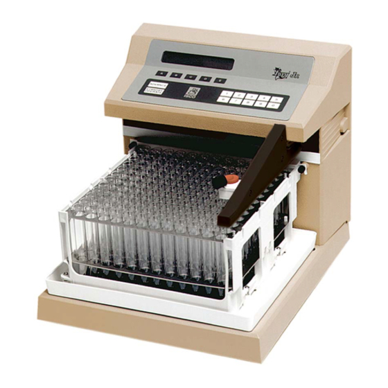
Teledyne Foxy Jr 1 Teledyne Foxy Jr Control Module 1 Teledyne Foxy Jr Control Module This manual describes the setting of the Teledyne Foxy Jr fraction collector. The control module enables direct control of the instrument over serial line Fig 1: Teledyne Foxy Jr fraction collector. -
Page 6: Requirements
Teledyne Foxy Jr 2 Requirements 2 Requirements Clarity Installation USB with appropriate control license allowed - LC Control (p/n A24) or GC Control module (p/n A23) for thermostats, valves and detectors, LC Control (p/n A24) for pumps and fraction collectors, GC Control module (p/n A23) for gas chromatographs or AS Control module (p/n A26) for autosamplers. -
Page 7: Installation Procedure
Teledyne Foxy Jr 3 Installation Procedure 3 Installation Procedure 3.1 Teledyne Foxy Jr fraction collector communication The Teledyne Foxy Jr is controlled by serial (RS232) communication. It uses a DB9F-DB25F straight cable (p/n SK04) described in the picture below. Fig 2: DB9F-DB25F... -
Page 8: Clarity Configuration
Teledyne Foxy Jr 3 Installation Procedure 3.2 Clarity Configuration Fig 3: How to add Teledyne Foxy Jr - 4 -... - Page 9 Note: DataApex UNI Setup dialog is described in detail in the chapter "DataApex UNI Setup" on pg 17. ④ The Teledyne Foxy Jr item will appear in the Setup Control Modules list of the System Configuration dialog. Drag the appropriate item from the Setup Control Modules list on the left ⑤...
-
Page 10: Using The Control Module
After adding and setting up the new device one or more new tabs will appear in the Metho depending on the type of the instrument. A new Teledyne Foxy Jrfraction collector section enabling the monitoring of the current fraction collector state will be also created in the Device Monitor window. -
Page 11: Method Setup - Fc - Fraction Table
4.1 Method Setup - FC - Fraction Table Method Setup - FC - Fraction Table tab is used for setting the automatic fraction collection program of the Teledyne Foxy Jr fraction collector. The actions of the fraction collector can be displayed in Data... - Page 12 Teledyne Foxy Jr 4 Using the control module has no waste/collect valve, this field should be left empty and he total tubing volume between the detector and fraction collector tray should be typed into the Delay Volume Detector - Valve field.
- Page 13 Teledyne Foxy Jr 4 Using the control module None - The fractions are collected in the defined time interval ruled by Start Time and Stop Time regardless of signal course. Level - The fraction collection: starts when the detector signal increases above the Level Start...
- Page 14 Teledyne Foxy Jr 4 Using the control module Note: It is strongly recommended not to use Slope Signal Condition for fraction collection based on noisy detector signal. Start L+S End L+S - The fraction collection: starts when both start signal conditions are fulfilled simultaneously, detector signal increases above Level Start value and also the first derivative of the detector signal increases above Slope Start value.
- Page 15 Teledyne Foxy Jr 4 Using the control module value. If none of the start signal conditions is fulfilled the fraction collection does not start. stops when any of the stop signal conditions is fulfilled (whatever occurs first), detector signal decreases below Level Stop value or the first derivative of the detector signal first decreases and then increases above the negative of the Slope Stop value.
-
Page 16: Method Setup - Fc - Vial Numbers
4.2 Method Setup - FC - Vial Numbers Method Setup - FC - Vial Numbers tab is used for setting the behavior of the Teledyne Foxy Jr fraction collector. Fig 7: Method Setup - FC - Vial Numbers Start Vial Number Vial Number Sets the number of the vial where the first collected fraction will be stored. - Page 17 Teledyne Foxy Jr 4 Using the control module After Last Vial Specifies the action executed when current vial number exceeds the Last Vial Number. Waste - the acquisition continues, but the fraction table is ignored and the samples are automatically discarded.
-
Page 18: Hardware Configuration
(invoked by using the FC Status button from the Method Setup - LC Method Setup - FC displays the configuration of the Teledyne Foxy Jr , namely the communication type and its parameters. Fig 8: Hardware Configuration - 14 -... -
Page 19: Device Monitor
Monitor - Device Monitor command from the Instrument window or using Device Monitor icon. Fig 9: Device Monitor - Teledyne Foxy jr Current Position Displays whether the fraction collector is currently wasting or the position to which it is currently collecting. -
Page 20: Data Acquisition Window
Teledyne Foxy Jr 4 Using the control module 4.5 Data Acquisition window Fig 10: Data Acquisition window Data Acquisition window can display the fractions in the graph using the background color and also the start and stop fraction events and marker of the Fraction Delay. -
Page 21: Dataapex Uni Setup
Value column) will be used throughout the Clarity station. Device Type Displays the subtype of the fraction collector. Baud Rate Sets the Baud Rate communication parameter for the Teledyne Foxy Jrfraction collector. Available values are 1200, 2400, 4800, 9600, 19200, 38400, 56800 and 115200 baud. - 17 -... - Page 22 Teledyne Foxy Jr 4 Using the control module Rack Selection Allows the user to select the correct rack type installed on the Teledyne Foxy Jr fraction collector. - 18 -...
-
Page 23: Report Setup
Teledyne Foxy Jr 5 Report Setup 5 Report Setup The fraction collector section on the method report can be enabled by checking the Instrument Control checkbox on the Method tab of the Report Setup dialog. Fig 12: Report Setup All of the parameters set in the... -
Page 24: Troubleshooting
Note: Instead of COM1, type the communication port used to communicate with the Teledyne Foxy Jrfraction collector. This port number is displayed when the FC Status button in the Method Setup - FC dialog is invoked. Note: %D (or %d) in the filename parameter means that the log will be created separately for each day.
Need help?
Do you have a question about the Foxy Jr and is the answer not in the manual?
Questions and answers