Table of Contents
Advertisement
Quick Links
Advertisement
Table of Contents

Related Manuals for DeviceWell UHS6610


Summary of Contents for DeviceWell UHS6610
- Page 1 Users’ Manual VER 1.0 4K UHD Switcher...
-
Page 2: Precautions
Due to the continuous update of product functions, the user manual in your hand may be different from the actual application. Please download the latest user manual from the Devicewell official website. The update date of this user manual is March 31, 2023. -
Page 3: Table Of Contents
SWITCHER 目录 Precautions…………………………………………………………………2 Overview……………………………………………………………...6 Product Introduction ............. 6 Function Features……………………………………………………..7 Size:384*252*92mm ............10 Interfaces…………………………………………………………….10 Interface Introduction ............10 Parameters ................12 Control Panel & Interfaces…………………………………………..13 Control Panel ..............13 Area Description ..............14 Button Description .............. 14 4.2.1. Audio Mixer ..............14 4.2.1.1. - Page 4 SWITCHER Multiview Output Window Introduction ......19 PGM&PVW Switching............20 T-bar Calibration ..............20 5.3.1. PGM and PVW Channel Selection by Panel ....... 22 5.3.2. Transition control..............23 5.3.3. PGM Output Black Field ............ 24 5.3.4. Audio Settings ..............24 Audio Introduction..............
- Page 5 SWITCHER WIPE Transition Effects ............. 31 5.5.3. INV mirror transition effects..........31 5.5.4. PIP Picture-In-Picture Special Effects ........ 32 5.5.5. POP Picture-Out-Picture Special Effect ......33 5.5.6. Luma KEY................35 5.5.7. Chroma KEY ..............36 5.5.8. System Menu Settings ............37 Menu Display ..............
-
Page 6: Overview
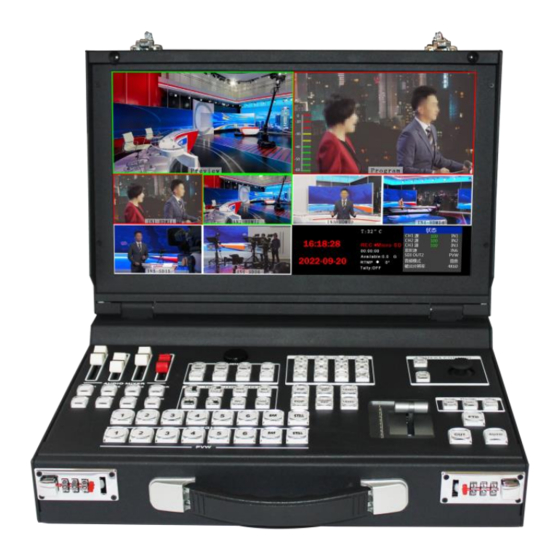
1. Overview Product Introduction Devicewell 4K UHD switcher UHS9610R/UHS9610/UHS9508R/UHS9508 integrates a variety of control methods, comes with a 15.6-inch HD monitor screen, can set special effects and transition methods through the keyboard, and the knob can control the LCD display The LCD screen will display various states of the current device in real time, the built-in menu display function can set the device more intuitively and efficiently, and the camera joystick can control the distance and distance of the camera. -
Page 7: Function Features
SWITCHER 2. Function Features DeviceWell switcher UHS9610R is a directing system with up to 6 cameras. It is suitable for many event projects. With the development of the times, especially in remote live broadcast of sports games, large -scale concerts or evening parties Especially in the event. If you want to use super multi-camera live directing... - Page 8 2.1 UHS Series 4K Switcher Function Comparison 4K Switcher Comparison Table Specifications and Parameters Video signal input Video signal output Model Tyoe Channel Channel HDMI (not real-time) (real time) Resolution UHS6610 4K@60HZ H*2+S*2 UHS6508 4K@60HZ H*2+S*2 UHS6512 4K@60HZ H*2+S*2 UHS6106 4K@60HZ H*2+S*2 UHS6108...
- Page 9 SWITCHER Stream & Record Control Others Model RTMP Record Playback Tally Remote Extension Style T-Bar stream stream UHS6610 RJ45 desktop Mechanical Hall UHS6508 RJ45 desktop Mechanical Hall UHS6512 RJ45 desktop Mechanical Hall UHS6106 RJ45 desktop Mechanical Hall UHS6108 RJ45 desktop...
-
Page 10: Size:384*252*92Mm
SWITCHER Size:384*252*92mm Interfaces Interface Introduction DeviceWell UHS9610R/UHS9508R interface is as shown below. - Page 11 SWITCHER Definition Description Definition Description HDMI OUT 4K Player HDMI OUT 2HDMI PGM OUT External storage device LINE IN/OUT 3.5mm Stereo audio in/out STREAM OUT Network Stream(reserved) MIC IN 2-ch microphone input Mouse/keyboard RJ45 Network upgrade AC 220V AC 220V power input DC 12V DC 12V power input HDMI IN...
-
Page 12: Parameters
SWITCHER Parameters Name 4K UHD Switcher Model UHS9610R/UHS9508R/UHS9610/UHS9508 Input signal HDMI/DP/SDI video signal Code rate 270Mbps~12Gbps Connector Standard Video Signal amplitude 800mV±10%( HDMI/SDI/DP) Signal Impedance 100Ω (HDMI) 100Ω (DP) 75Ω (SDI) Input Balance Adaptive DVD input 480i/576i,480p/576p,720p,1080i,1080p,2160p HDMI support HDMI/DP 3840x2160,1920x1080,1680x1050,1600x900,1440x1050,1366x768,1360x768,1280x1024, 1280x960,1280x800,1280x768,1280x720,1280x600,1152x864,1024x768,800x600 input support... -
Page 13: Control Panel & Interfaces
Please take a few minutes to read this chapter before using DeviceWell HD switcher equipment. This chapter will give you a detailed introduction to the panels and interfaces of the DeviceWell HD switcher, so as to facilitate your subsequent use and operation. -
Page 14: Area Description
SWITCHER Area Description Name Description Mixer Mainly for audio follow, embedded and mix settings Knob control area Use the knob to display menu information and various states of the switcher system Camera control area Switch 1-6 camera Camera lens control area Control camera distance Transition effect control area Select transition effects... -
Page 15: Knob And Key Menu
SWITCHER 4.2.1.2. Knob and Key Menu UHS9610R can be set by knob 1. Rotate clockwise to down to increase the value. 2. Rotate counterclockwise to the up to decrease value. 3. Press to select. Press the key to start recording Press the key to play start/pause Press the key to pause recording View the direction key of the recorded file... -
Page 16: Camera Control
SWITCHER 4.2.1.3. Camera Control The UHS9610R switcher supports 6-channel camera control, and the distance and distance of the 6-channel cameras can be controlled through the joystick. When the CAMCTRL key is on, press any key from 1 to 6 again, and after the number key is on, you can control the corresponding camera. -
Page 17: Camera Lens Control
SWITCHER 4.2.1.4. Camera Lens Control Zoom in/increase the shooting distance Zoom out/ reduced shooting distance Push the camera rocker up: the lens is up Push the camera rocker down: the lens is down Push the camera rocker left: rotate the lens counterclockwise Push the camera rocker right: rotate the lens clockwise 4.2.1.5. - Page 18 SWITCHER Chroma key, press the button to deduct the specified color and overlay it with the background source. Level adjustment of the KEY, long press can quickly increase the level Level adjustment of the KEY, long press can quickly decrease the level PIP special effects button, open picture-in-picture function POP special effects button, open picture-out-picture...
-
Page 19: T-Bar
SWITCHER 4.2.1.8. T-Bar The switcher T-Bar system consists of a pusher module and an indicator light. Pushing the T-bar up can complete the transition. When the T-bar is pushed, the indicator light will follow the movement to the top 1 (the pusher pushes to the bottom and the top is a light). -
Page 20: Pgm&Pvw Switching
SWITCHER Preview and Program are PVW and PGM output respectively; as shown below: Preview Program There are 6 windows below that correspond to the input source monitoring, corresponding to the 1 - 6 buttons on the control panel. PGM&PVW Switching T-bar Calibration 5.3.1. - Page 21 SWITCHER At this time, push the T-bar back and forth until the indication is normal. (All lights up or all lights down) as shown below. The picture on the left shows the status of the push indicator light from bottom to top. If the display on the left indicates that the calibration is complete, you can release the 1 and 2 buttons that were previously pressed.
-
Page 22: Pgm And Pvw Channel Selection By Panel
SWITCHER Then press the AUTO, CUT, or manually push the fader on the control panel to switch. Among them, AUTO can be set to switch effects, CUT is hard cut, no transition effect, manual putter can set special effects, and push speed is proportional to the speed of switching. -
Page 23: Transition Control
2 (PGM) and 1 (PVW), just press 2 (PGM) and 1 ( PVW), and then click AUTO or CUT to switch. The live PGM signal source 1-6 can be switched arbitrarily with the preview PVW signal source. As shown below 5.3.3. Transition control The transition control method of DeviceWell UHS9610R... -
Page 24: Pgm Output Black Field
SWITCHER Portable switcher is mainly divided into two types, one is transition special effect, and the other is transition mode without transition special effect. 1. No transition effect: Press CUT, CUT button is hard cut. If you select the preview (PVW) screen to switch directly to the main output (PGM), because there is no delay seamless switching, there is no transition effect. -
Page 25: Audio Description Of Mixer Control Area
SWITCHER Audio modes are divided into Mix and Follow. Audio description of mixer control area 5.4.2. 5.4.2.1. Audio Introduction The UHS9610R switcher supports analog balanced audio input and output; supports SDI audio de-embedding, external audio and SDI de-embedded audio can be arbitrarily assigned to output, supports audio follow and mix switching functions, the menu and panel display as shown below. -
Page 26: Audio Source Switching
SWITCHER The knob can be switched to the mix mode (default follow mode). After setting to the mix mode, press INPUT1, INPUT2, and INPUT3 to turn on the mix mode. Up to 3 channels can be mixed. The sound can be adjusted by the audio fader. -
Page 27: How To Use The Audio Follow Mode
SWITCHER 5.4.3.2. How to use the audio follow mode 1. First adjust the audio mode to follow by the knob Press the mixer's MASTER button (the button lights up in green) The channel of the audio follow mode is turned on, pushes the corresponding red fader upwards, adjusts the volume of the PGM output, and switches the video signal with audio to the PGM window. -
Page 28: How To Use The Mix Assignment
SWITCHER 5.4.3.4. How to use the mix assignment 1. Adjust the audio mode to Mixing by the knob first (As shown in Figure 1) Corresponding to the status bar of the LCD screen, the audio channel source is displayed. The factory default is CH1 source IN1, CH2 source IN2, CH3 source IN3.( As shown in Figure 2) 2. - Page 29 SWITCHER 3. Operate the mixer control area, press the SRC2 button to enter the second audio channel to select IN1, IN2, IN3, IN4, IN5, IN6、XLR_IN. The corresponding menu status bar will change according to your choice in real time. (as shown in Figure 1) After confirming the audio channel you selected, press the CH2 button (as shown in Figure 2) It means to open the second audio channel, push the white fader corresponding to the second channel, and adjust the volume of the second channel audio.
-
Page 30: Special Effects Instructions
SWITCHER Special effects instructions 5.5.1. MIX Transition Effects The MIX blend effect is a transition effect. After setting, the transition will have the original live screen fade in the main output and then disappear until it disappears completely to the new live screen, as shown below. MIX mixed transition effect, superimposed and superimposed B picture in A picture until the transition to the end, the picture is completely replaced with B picture Select the effect control area MIX and then click to use the T-bar or AUTO to switch. -
Page 31: Wipe Transition Effects
SWITCHER FADE fades in and out, and A gradually darkens until it is completely black, and then gradually changes from black to B. 5.5.3. WIPE Transition Effects Press WIPE to select the mode of the wipe, there are 4 modes. As shown on the right After selecting the way of the wipe, click on AUTO or push the T-bar You can see the effect of the switch. -
Page 32: Pip Picture-In-Picture Special Effects
SWITCHER The INV mirror transition is opposite to the original WIPE transition. When you press WIPE and INV in the key panel, and then press the upward transition direction , the screen that appears will be the downward transition, and the effect diagram is shown below. 5.5.5. -
Page 33: Pop Picture-Out-Picture Special Effect
SWITCHER Screen Select Horizontal PIP size and position Vertical Display Size Large Border Switch Border Width Border Color Green Exit You can use the knob to set the parameters of the PIP picture-in-picture, as follows: Horizontal position setting: The value from the top left to the top right is 0-1280, and the value of each rotation knob is increased/decreased by 10. - Page 34 SWITCHER At this time, the information on the LCD screen will be switched to the POP picture-out-picture setting, and the knob can be set as required. As shown below Window H Position V Position Size Large Border Enable Border Width Border Color Green POP size and position...
-
Page 35: Luma Key
SWITCHER 5.5.7. Luma KEY The Luma key image supports the dynamic video source image and the static source image. The switcher will deduct the black part of the key source and retain other colors. Then it overlaps with the background image to achieve the purpose of keying and superimposing the background. -
Page 36: Chroma Key
SWITCHER 5.5.8. Chroma KEY The chroma key image supports dynamic video source image and static source image, switching the opportunity to buckle the blue or green part of the key source, retaining other colors, and then overlapping the background image to achieve the purpose of image and overlay background. Generally used for superimposing subtitles in virtual studios. -
Page 37: System Menu Settings
SWITCHER System Menu Settings 5.6.1. Menu Display In the menu, you can perform IP settings on the device, restore the system to factory settings, change the language, etc. In the power-on default state, press the knob to enter the main menu. As shown below Status Main Manu System Settings... -
Page 38: Network Settings
SWITCHER In this menu, you can choose between Chinese or English. If you encounter an unknown error during use, you can choose to restore the factory settings and reset it. 5.6.3. Network Settings Network Settings There are two modes for obtaining an IP address. One IP Source static IP is dynamic configuration, and the other is a static IP... -
Page 39: Device Info
SWITCHER 5.6.5. Recording Settings The storage mode can be set in the recording settings. You can select USB flash disk/SATA Recording Settings hard disk. The LED will flash when recording, Encoding and the status of recording will be displayed in real time in the status display bar of the Storage Type USB Disk... -
Page 40: Failure And Maintenance
SWITCHER 6. Failure and Maintenance Common Faults and Solutions (1) The output image may be flickered by interference. The quality of the wire used may be poor, and the shielding layer of the wire is not well prepared. When there is a strong radio near the use environment, radio waves may interfere with the transmission of the signal, resulting in unstable signal flicker. - Page 41 SWITCHER http://www.devicewell.com...
Need help?
Do you have a question about the UHS6610 and is the answer not in the manual?
Questions and answers