Advertisement
Quick Links
Advertisement

Related Manuals for FRENCH FITNESS MFAB


Summary of Contents for FRENCH FITNESS MFAB
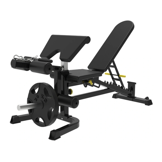
- Page 1 MFAB MULTI FUNCTIONAL ADJUSTABLE BENCH ASSEMBLY MANUAL...
- Page 2 ...
-
Page 3: Table Of Contents
Contents Parts list ……………………………………………………………………………………………………………………………..3-4 Assembly step 1 ………………………………………………………………………………………………………………...5-7 Assembly step 2 ……………………………………………………………………………………………………………..8-10 Assembly step 3 ……………………………………………………………………………………………………………..11-13 Assembly step 4 ……………………………………………………………………………………………………………..14-16 Assembly step 5 ……………………………………………………………………………………………………………..17-19 Assembly step 6 ……………………………………………………………………………………………………………..20-22 Assembly step 7 ……………………………………………………………………………………………………………..23-24... -
Page 4: Parts List
Parts list Serial NO. Description Note Qty. BK-3018-1 middle base frame BK-3018-2 front bending base frame BK-3018-3 back base frame BK-3018-4 hexagon bolt M10*70 BK-3018-5 gasket Φ12 BK-3018-6 lock nut BK-3018-8 bending tube BK-3018-9 hexagon bolt M10*20 BK-3018-10 gasket Φ10 BK-3018-11 locking spring knob M18*1.5-35... - Page 5 Parts list BK-3018-43 foot cover □50*50 BK-3018-44 rivet nut BK-3018-45 foot cover □50*70 BK-3018-46 roller Φ54 BK-3018-48 lock nut BK-3018-49 powder metallurgy sleeve Φ32*Φ28*Φ20*18 BK-3018-50 tube plug □50*50/□45*45 BK-3018-51 bearing 6001 BK-3018-52 tube plug □40*60*2 BK-3018-53 tube Φ50*0.8 BK-3018-54 tube plug □45*45 BK-3018-55 handle cover...
-
Page 6: Assembly Step 1
Assembly step-1 explosion drawing No. Descrip on Note Qty. middle base frame front bending base frame back base frame hexagon bolt M10*70 gasket Φ12 lock nut... - Page 7 Factory assembly explosion drawing No. Descrip on Note Qty. foot cover □50*50 rivet nut No. Descrip on Note Qty. gasket Φ8 foot cover □50*70 roller Φ54 21 hexagon bolt M8*45 lock nut...
- Page 8 Assembly step-1 drawing Assembly step-1 installation instruction 1 Fix middle base frame-1 and front bending base frame-2 using M12*70 hexagon bolt-4, Φ12 gasket-5, M12 lock nut-6. 2 Fix back base frame-3 fastening on middle base frame-1 using M12*90 hexagon bolt-7, Φ12 gasket-5, M12 lock nut-6.
-
Page 9: Assembly Step 2
Assembly step-2 explosion drawing No. Descrip on Note Qty. bending tube hexagon bolt M10*20 gasket Φ10 locking spring knob M18*1.5-35 spring gasket Φ10... - Page 10 Factory assembly explosion drawing No. Description Note Qty. powder metallurgy sleeve Φ32*Φ28*Φ20*18 tube plug □50*50/□45*45...
- Page 11 Assembly step-2 drawing Assembly step-2 installation instruction 1 Fix bending tube-8 fastening on main frame using M10*25 hexagon bolt-42, Φ10 gasket-10, Φ10 spring gasket-12. 2 Put locking spring knob-11 on the bending tube-8.
-
Page 12: Assembly Step 3
Assembly step-3 explosion drawing No. Description Note Qty. back pad tube shaft Φ12*128-M10 gasket Φ10 lock nut selector tube big gasket Φ30*Φ10.5*3.0 hexagon bolt M10*20 back pad rotating sleeve locking spring knob M18*1.5-35 spring gasket Φ10... - Page 13 Factory assembly explosion drawing No. Descrip on Note Qty. bearing 6001 tube plug □40*60*2 No. Descrip on Note Qty. powder metallurgy sleeve Φ32*Φ28*Φ20*18 tube plug □45*45...
- Page 14 Assembly step-3 drawing Assembly step-3 installation instruction 1 Fix selector tube-16, back pad rotating sleeve-18 and locking spring knob-11 on the main frame. 2 Connect back pad tube-13, selector tube-16 and main frame using shaft-14, Φ10 gasket -10 and M10 lock nut-15. 3 Fix selector tube-16 and back pad rotating sleeve-18 using M10*20 hexagon bolt-9, Φ10 big gasket-17 and Φ10 spring gasket-12.
-
Page 15: Assembly Step 4
Assembly step-4 explosion drawing No. Description Note Qty. shaft Φ12*128-M10 seat pad frame gasket Φ10 lock nut magnetic pin Φ10*80... - Page 16 Factory assembly explosion drawing No. Description Note Qty. bearing 6001 tube plug □40*60*2...
- Page 17 Assembly step-4 drawing Assembly step-4 installation instruction 1 Fix seat pad frame-19 on the main frame using shaft-14, Φ10 gasket-10, M10 lock 2 Put magnetic pin-41 on the main frame.
-
Page 18: Assembly Step 5
Assembly step-5 explosion drawing No. Description Note Qty. seat pad hexagon bolt M8*45 gasket Φ8 hexagon bolt M8*20 back pad foam rod-450 foam inner cover foam outer cover foam Φ100*175 allen bolt M8*20 ROUND leg curl tube magnetic pin Φ10*80... - Page 19 Factory assembly explosion drawing No. Description Note Qty. handle cover Φ32*Φ25*130 tube plug Φ32*Φ29*Φ26*29 tube plug □50*50/Φ32...
- Page 20 Assembly step-5 drawing Assembly step-5 installation instruction 1 Fix the seat pad-20 and back pad-24 onto the main frame using Φ8 gasket-22, M8*25 hexagon bolt-23. 2 Fix foam tube-28, foam inner cover-29, foam-31 and foam outer cover-30 into the leg curl tube as shown in the figure using M8*25 allen bolt. 3 Put the leg curl tube-40 to the main body and fix them with magnetic pin-41.
-
Page 21: Assembly Step 6
Assembly step-6 explosion drawing No. Description Note Qty. leg curl tube shaft Φ20*57-M10 hexagon bolt M10*20 gasket Φ10 T shape pin-85 Φ10*85 foam rod-450 foam inner cover foam outer cover foam Φ100*175 allen bolt M8*20 ROUND upright tube spring gasket Φ10 spring collar Φ50... - Page 22 Factory assembly explosion drawing No. Description Note Qty. tube plug Φ32*Φ29*Φ26*29 tube plug □50*50*2.0 powder metallurgy sleeve Φ32*Φ28*Φ20*18 tube Φ50*0.8 tube Φ48*1.5 tube plug Φ50*Φ44.8*Φ25.5 tube plug Φ70*Φ44.8*Φ25.5*30 rubber cushion Φ40*Φ25*29 allen bolt M8*20...
- Page 23 Assembly step-6 drawing Assembly step-6 installation instruction 1 Fix shaft-26 and upright tube-33 fastening on leg curl tube-25 using Φ10 washer- 10, Φ10 spring washer-12 and M10*20 hexagon bolt-9. 2 Assemble the foam rod-28, foam inner cover-29, foam-31 and foam outer cover-30 to leg curl tube-25 as shown in the figure, and fix it with M8*25 allen bolt-32 at both ends.
-
Page 24: Assembly Step 7
Assembly step-7 explosion drawing No. Descrip on Note Qty. chest pad hexagon bolt M8*20 gasket Φ8 barbell support tube hexagon bolt M10*65 gasket Φ10 lock nut chest pad tube... - Page 25 Assembly step-7 drawing Assembly step-7 installation instruction 1 As shown in the figure fix barbell support tube-36 fastening on the chest pad tube-39 using M10*65 hexagon head bolt-38, Φ10 gasket-10 2 Fix chest pad-35 onto the chest pad tube-39 and fix it with M8*25 hexagon bolt-23. 3 Assemble the whole set of barbell supporting trusteeship accessories onto the main body with adjustable height.When not needed, the attachment can be removed at any time, and the attachment can be replaced to achieve other training...
Need help?
Do you have a question about the MFAB and is the answer not in the manual?
Questions and answers