
Subscribe to Our Youtube Channel
Related Manuals for FRENCH FITNESS MSC10


Summary of Contents for FRENCH FITNESS MSC10
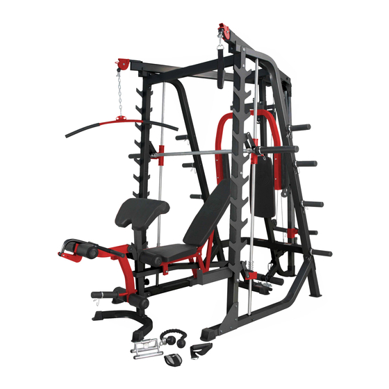
- Page 1 FF-MSC10 DELUXE SMITH MACHINE OWNER’S MANUAL CAUTION! Read all precautions and instructions in this manual before using this equipment. 20201211-V1.0...
-
Page 2: Table Of Contents
EXPLODED DIAGRAM…………………………………………………………….. MULTI-PURPOSE BENCH PARTS LIST………………………………………… BEFORE YOU BEGIN Thank you for selecting the FF-MSC10. For your safety and benefit, read this manual carefully before using the machine. As a manufacturer, we are committed to provide you complete customer satisfaction. -
Page 3: Important Safety Notices
IMPORTANT SAFETY NOTICE PRECAUTIONS This exercise machine is built for optimum safety. However, certain precautions apply whenever you operate a piece of exercise equipment. Be sure to read the entire manual before you assemble or operate your machine. In particular, note the following safety precautions: 1. - Page 4 WARNING LABEL PLACEMENT...
-
Page 5: Smith Machine Hardware Pack
SMITH MACHINE HARDWARE PACK NOTE:The following parts are not drawn to scale. Please use your own ruler to measure the size. - Page 6 SMITH MACHINE HARDWARE PACK NOTE:The following parts are not drawn to scale. Please use your own ruler to measure the size.
- Page 7 SMITH MACHINE HARDWARE PACK NOTE:The following parts are not drawn to scale. Please use your own ruler to measure the size.
-
Page 8: Smith Machine Assembly Instructions
SMITH MACHINE ASSEMBLY INSTRUCTION Tools Required Assembling the Machine: Two Adjustable Wrenches and Allen Wrenches. NOTE: It is strongly recommended two or more people assembling this machine to avoid possible injury. STEP 1 (See Diagram 1) Do not tighten all nuts and bolts until instructed to do so. Connect the Base Frame (#6) to the Front Vertical Frame (#1) using the Inclined Bracket (#41) and four Hex Bolts M12X90 (#85), eight Washersφ... - Page 9 DIAGRAM 1 108 103...
- Page 10 STEP 2 (See Diagram 2) A.) Attach the Foot Frame (#18) to the Rear Support Frame (#16) using two Hex Bolts M10X20 (#95) and two Washersφ 10 (#103). B.) Attach the Rear Vertical Frame (#10) and the combined piece (#16, #18) to the Cross Brace (#7) using two Hex Bolts M10X95 (#86), four Washersφ...
- Page 11 STEP 3 (See Diagram 3) A.) Attach the Weight Glide Post(#20)to the Rear Support Frame (#16) using the Bracket (#43) and two Hex Bolts M10X75 (#89),three Washersφ 10 (#103), one Nut M10 (#108). B.) Slide the Sliding Weight Post (#19) onto the Weight Glide Post(#20). Ensure it is correctly orientated.
- Page 12 STEP 4 (See Diagram 4) A.) Attach the Left Upper Frame(#8)onto the Left Vertical Frame(#3).Connect it with the Upper Frame (#17) using one Bracket (#42) and two Hex Bolts M10×70 (#90),four Washers φ10(#103),two Nuts M10 (#108).Repeat the same procedure to secure the other side.
- Page 13 STEP 5 (See Diagram 5) A) Securely tighten all Nuts and Bolts previously installed. Align the Butterfly Base (#11) and the Butterfly Pulley Bracket (#14) with the correct B) holes on the Rear Vertical Frame (#10) .Attach using two Hex Bolts M10X70 (#90), four Washersφ10 (#103) and two Nuts M10 (#108) C)...
- Page 14 CABLE LOOP DIAGRAM...
- Page 15 STEP 6 (See Diagram 6& Cable Loop Diagram) A.) Install the Ball Stopper, Big Washer and the U-shaped Connector to one end of the Upper Cable 6895 (#47). Secure it with one Hex Bolt M10×35 (#93),Nut M10 (#108) and two Washersφ 10 (#103). Insert the other end of Cable through the left Cross-over Swivel Pulley Bracket (#38).
- Page 17 STEP 7 (See Diagram 7 & Cable Loop Diagram) A.) Attach one end of Butterfly Cable 2200 (#46) to the clip on Right Butterfly (#13). Draw the Cable to the right Swivel Pulley Bracket (#15). B.) Attach a Pulley (#50) to the Bracket. Secure it with one Hex Bolt M10×45 (#92), two Washers φ...
- Page 18 STEP 8 (See Diagram 8 & Cable Loop Diagram) A.) Attach one end of the Sliding Weight Post Cable 3710 (#49) to the open bracket on the Sliding Weight Post (#19). Secure it with one Hex Bolt M10×25 (#88), two Washersφ 10 (#103), and one Nut M10 (#108).
- Page 19 STEP 9 (See Diagram 9 & Cable Loop Diagram) A.) Attach the Lower Cable 1480 (#48) to a Pulley (#50). Attach the Pulley to the lower opening on the Rear Support Frame (#16). Secure it with the one Hex Bolt M10×65 (#91), two Pulley Bushings (#66), and one Nut M10 (#108).
- Page 20 STEP 10 (See Diagram 10) A.) NOTE: Help of another person is strongly recommended for this step. Place the Lifting Sleeve (#23) in between the two Safety Stop Frames (#25). Align the holes. Insert the Weight Bar (#28) into the Safety Stop Frame from one end and through the Lifting Sleeve (#23) to the other Safety Stop Frame on the opposite side.
- Page 21 SMITH CAGE EXPLODED DIAGRAM...
- Page 22 PARTS LIST DESCRIPTION SPEC Q'TY DESCRIPTION SPEC Q'TY Front Vertical Frame □50×70×2×1997 V Bar Triple Floating Pulley Vertical Base Frame Bracket Little Single Floating Left Vertical Frame Pulley Bracket Cross-Over Swivel Right Vertical Frame Pulley Bracket Front Top Beam Bushing φ24.5×φ18.5×15 Base Frame Side Rack...
- Page 23 Q'TY DESCRIPTION SPEC DESCRIPTION SPEC Q'TY Bushing φ38×φ34×φ27×26 Washer φ21 Rubber Bumper 60×50×4 Chain Rubber Bumper 280×48×5 Aircraft Nut End Cap φ60 Aircraft Nut End Cap φ25 Aircraft Nut End Cap φ25 Spring Clip φ24.5 End Cap □38 End Cap □45 End Cap □50...
- Page 24 SMITH MACHINE HARDWARE PACK NOTE:The following parts are not drawn to scale. Please use your own ruler to measure the size.
-
Page 25: Multi-Purpose Bench Assembly Instructions
MULTI-PURPOSE BENCH ASSEMBLY INSTRUCTION Tools Required Assembling the Machine: Two Adjustable Wrenches and Allen Wrenches. NOTE: It is strongly recommended this machine be assembled by two or more people to avoid possible injury. STEP 1 (See Diagram 1) A.) Attach the Main Frame (#1) to the Front & Rear Stabilizers (#2 & 3). Secure each end with two M10 x 20 Allen Bolts (#36) and ∅... - Page 26 STEP 2 (See Diagram 2) A.) Attach four Bushings (#27) to a Seat Support Frame (#6). B.) Attach a Backrest Support (#7) to the rear of the Seat Support Frame (#6). Align the holes and secure them with one M10 x 45 Allen Bolt (#37) and ∅10 Washer (#42). Repeat the same procedure to install the other side.
- Page 27 STEP 3 (See Diagram 3) A.) Place the Backrest Board (#14) onto the Backrest Supports (#7). Secure it with four M8 x 50 Allen Bolts (#40) and ∅ 8 Washers (#43). B.) Place the Seat Pad (#13) onto the Seat Support Frames (#6). Secure it with four M8 x 50 Allen Bolts (#40) and ∅...
- Page 28 STEP 4 (See Diagram 4) A.) Attach the Leg Developer (#5) to the open bracket on the Main Frame (#1). Secure it with an Axle (#17), two M10 x 20 Allen Bolts (#36), and two ∅ 10 Washers (#42). Insert one Foam Tube (#10) halfway through the hole on the Main Frame. Insert two Foam Tubes halfway through the holes on the Leg Developer (#5).
- Page 29 STEP 5 (See Diagram 5) A.) Attach the Arm Curl Pad (#15) to the Arm Curl Stand (#4). Secure it with two M8 x 16Allen Bolts (#41) and two ∅ 8 Washers (#43). Insert the Arm Curl Stand into the front opening on the Main Frame (#1).
- Page 30 SMITH CAGE EXPLODED DIAGRAM...
- Page 31 PARTS LIST DESCRIPTION SPEC Q'TY DESCRIPTION SPEC Q'TY Main Frame Allen Bolt M10×45 Front Stabilizer Allen Bolt M10×170 Rear Stabilizer Allen Bolt M10×210 Arm Curl Stand Allen Bolt M8×50 Leg Developer Allen Bolt M8×16 Seat Support Bracket Washer Backrest Support Washer Sliding Block Aricraft Nut...
- Page 32 FF-MSC10-AB DELUXE SMITH MACHINE OWNER’S MANUAL CAUTION! Read all precautions and instructions in this manual before using this equipment. 20201211-V1.0...
- Page 33 ASSEMBLY MANUAL FF-MSC10-AB BENCH BEFORE YOU START Remove all parts from the packaging, separate and count each various component, to ensure everything has been correctly provided. Follow the instructions and consult both the individual assembly pages and the overall expanded views of the equipment.
- Page 34 Exercise Guidelines PERSONALIZING YOUR EXERCISE PROGRAM THE FOUR BASIC TYPES OF WORKOUTS Specifying the exact length of time for each workout, Muscle Building as well as the number of repetitions or sets for each The only way to increase the size and strength of exercise, is a highly individual matter.
- Page 35 You should rest for a short period of time after each without strain. Stretching at the end of each workout set. The ideal resting periods are: is very effective for increasing flexibility. Rest three minutes after each set for a muscle •...
- Page 36 PARTS LIST KEY NO. PART DESCRIPTION SPEC Q'TY Main Frame Rear Base Frame Front Base Frame Seat Support Backrest Support Foam Roll Support Adjustment Support Rear Support Foam Roll Frame Seat Pad Backrest Board Tensile Spring φ15×φ2×65 Pop Pin φ10×110 Lock Knob M18×φ10 Handle Grip...
- Page 37 ASSEMBLY DIAGRAM 1 REMEMBER: Only hand tighten all nuts and bolts until whole FF-MSC10-AB is assembled Ensuring correct orientation, attach the front of the MAIN FRAME (1) to the FRONT BASE FRAME (3) using two STEP BOLT M10X70 (39), two WASHER10 (33) and two AIRCRAFT NUT M10...
- Page 38 ASSEMBLY DIAGRAM 2 REMEMBER: Only hand tighten all nuts and bolts until whole FF-MSC10-AB is assembled Ensuring correct orientation, attach the SEAT SUPPORT (4) to the front holes in the upright bracket on the MAIN FRAME (1) using a HEX BOLT M12X95 (28), two WASHER12 (34) and an...
- Page 39 ASSEMBLY DIAGRAM 3 REMEMBER: Only hand tighten all nuts and bolts until whole FF-MSC10-AB is assembled Attach the BACKREST BOARD (11) to the BACKREST SUPPORT (5) using two HEX BOLT M8X55 (23) and two WASHER8 (32) Attach the SEAT PAD (10) to the SEAT SUPPORT (4) using two HEX BOLT M8X55 (23) and...
-
Page 40: Exploded Diagram
EXPLODED DIAGRAM... - Page 41 HARDWARE FF-MSC10-AB...
- Page 42 FF-MSC10-AC DELUXE SMITH MACHINE FF-MSC10-AB BENCH – PREACHER CURL ATTACHMENT OWNER’S MANUAL CAUTION! Read all precautions and instructions in this manual before using this equipment. 20201211-V1.0...
- Page 43 PARTS LIST AND HARDWARE…......…...…....ASSEMBLY DIAGRAM …………………………………………………………… BEFORE YOU BEGIN Thank you for selecting the FF-MSC10-AC. For your safety and benefit, read this manual carefully before using the machine. As a manufacturer, we are committed to provide you complete customer...
- Page 44 IMPORTANT SAFETY NOTICE PRECAUTIONS This exercise machine is built for optimum safety. However, certain precautions apply whenever you operate a piece of exercise equipment. Be sure to read the entire manual before you assemble or operate your machine. In particular, note the following safety precautions: 1.
- Page 45 PARTS LIST AND HARDWARE KEY NO. PART DESCRIPTION SPEC Q'TY Arm Curl Stand Arm Curl Pad Hex Bolt M8×20 Washer...
- Page 46 MAIN FRAME ( FF-MSC10-AB 1) Insert the ARM CURL STAND (1) into the top of the post at the front of the MAIN FRAME ( FF-MSC10-AB 1) Attach the ARM CURL PAD (2) to the top of the ARM CURL STAND (1) using two HEX BOLT M8X20 (3) and...
- Page 47 FF-MSC10-LA DELUXE SMITH MACHINE FF-MSC10-AB BENCH – LEG CURL / LEG EXTENSION OWNER’S MANUAL CAUTION! Read all precautions and instructions in this manual before using this equipment. 20201211-V1.0...
- Page 48 ASSEMBLY DIAGRAM..................EXPLODED DIAGRAM……………………………………………………………. PARTS LIST………………………………………………………………………… BEFORE YOU BEGIN Thank you for selecting the FF-MSC10-LA. For your safety and benefit, read this manual carefully before using the machine. As a manufacturer, we are committed to provide you complete customer satisfaction.
- Page 49 IMPORTANT SAFETY NOTICE PRECAUTIONS This exercise machine is buiIt for optimum safety. However, certain precautions appIy whenever you operate a piece of exercise equipment. Be sure to read the entire manuaI before you assembIe or operate your machine. In particuIar, note the foIIowing safety precautions: 1.
- Page 50 PARTS LIST AND HARDWARE KEY NO. PART DESCRIPTION SPEC Q'TY Leg Developer Holder Leg Developer Foam Frame U shaped Lock Pin 60×62×28×φ10 ×M6 End Cap □ 45 Foam Roll φ125×φ22× 215 Foam Baffle φ68×5.7 Olympic Sleeve φ50×21 0 Rubber Bumper φ30×φ25×...
- Page 51 ASSEMBLY DIAGRAM 1 REMEMBER: Only hand tighten all nuts and bolts until whole FF-MSC10-LA is assembled 1. Remove the assembled and attached FOAM ROLL SUPPORT (FF-MSC10-AB 6) from the front of the MAIN FRAME (FF-MSC10-AB 1) 2. Ensuring correct orientation. insert the LEG DEVELOPER HOLDER (1) into the top of the front...
- Page 52 ASSEMBLY DIAGRAM 2 REMEMBER: Only hand tighten all nuts and bolts until whole FF-MSC10-LA is assembled 1. Attach the RUBBER BUMPER (9) and the WASHER 25X11X2 (17) to the back of the LEG DEVELOPER (2). Inset the U-SHAPED LOCK PIN (4) into the top of the post on the LEG...
- Page 53 ASSEMBLY DIAGRAM 3 REMEMBER: Only hand tighten all nuts and bolts until w hole FF-MSC10-LA is assembled Insert the two FOAM FRAMES (3) into the holes on the LEG DEVELOPER (2) Slide a FOAM ROLL (6) onto each end of the FOAM FRAMES (3). Attach each one using a FOAM BAFFLE (7)
- Page 54 EXPLODED DIAGRAM...
Need help?
Do you have a question about the MSC10 and is the answer not in the manual?
Questions and answers