Table of Contents
Advertisement
Quick Links
Advertisement
Table of Contents

Related Manuals for FRENCH FITNESS X9


Summary of Contents for FRENCH FITNESS X9
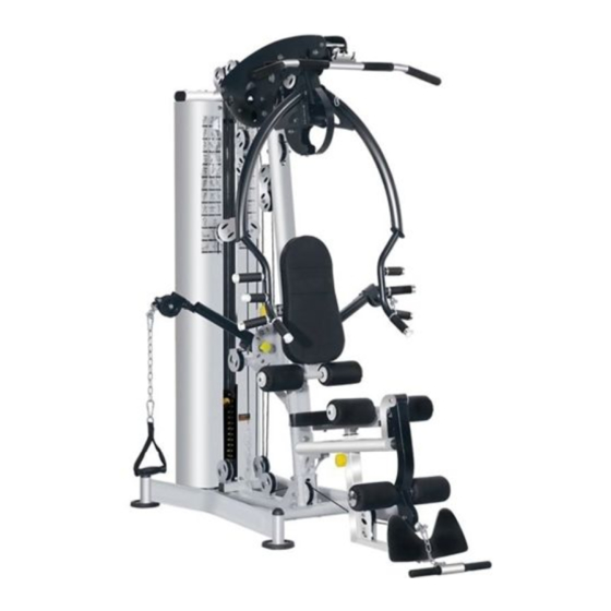
- Page 1 FUNCTIONAL MULTI GYM SYSTEM ASSEMBLY MANUAL...
- Page 2 FEATURES • Heavy duty steel construction • Thick pads with extra support and cushioning • Space saving design • Adjustable seat height and back rest to perform various exercises with ease • Reinforced nylon pulleyʼs with precision machined steel ball bearings •...
-
Page 3: Table Of Contents
Table of Contents Detail List Detail List Parts Diagram Fastening Parts Diagram Installing Step 1 Installing Step 2 9-10 Installing Step 3 11-12 Installing Step 4 13-14 15-16 Installing Step 5 Installing Step 6 17-18 19-20 Installing Step 7 21-22 Installing Step 8 23-25 Installing Step 9... - Page 4 Parts Detail List Parts Name Specification Quantity Underframe Assembly Packaging parts Guiding rod assembly Ф25*1853 Back supporting tube assembly Ф25*1757.5 Outer hex bolt M10*65 Gasket Ф10 Outer hex bolt M10*20 Counterweight limiting rubber pad Ф60*Ф26*20 Inner hex round head bolt M8*70 Lock nut Lifting rod weldment assembly...
- Page 5 Parts Detail List Parts Name Specification Quantity Inner hex flat head screw M10*16 Long semicircle piece Packaging parts Pedal board weldment assembly Assembly parts Outer hex bolt M10X70 cross pulley frame paint parts Pulley-Johnson Ф95*26 Protection plate connecting sleeve Ф14*100 Steel wire rope hook Assembly parts Spring washer...
-
Page 6: Parts Diagram
Parts Diagram... -
Page 7: Fastening Parts Diagram
Steel Wire Rope Diagram Fastening Parts Diagram Bolt Length Measurement Table... -
Page 8: Installing Step
Installing Step 1 Exploded Diagram... - Page 9 Installation Step 1 Assembly Diagram Installation Step 1 Installation Instruction 1.Put 10 spring washer (84) and 10 washer (5) over M10*65 outer hexagonal bolt (4), a nd fasten the rear supporting tube assembly (3) to the underframe weldment assembly (1) 2.
- Page 10 Installing Step 2 Exploded Diagram cast iron counterweight upper block (12) partial view zoom-in...
- Page 11 Installation Step 2 Assembly Diagram Installation Step 2 Installation Instruction 1. Place 9PCS of cast iron counterweight lower blocks (11) and the upper blocks (12) on top of the guiding rod assembly; among which, the largest weight marked of the cast iron counterweight lower block (11) is placed on the top, and the lowest weight is placed on top 2.
-
Page 12: Installing Step
Installing Step 3 Exploded Diagram... - Page 13 Installation Step 3 Assembly Diagram Installation Step 3 Installation Instruction 1. Fasten the inclined supporting beam assembly (25) on the underframe weldment assembly with M12*70 outer hexagonal bolts (19), 12 gaskets (20), M12 lock nuts (21) 2. Use M10*130 outer hexagonal bolts (22), 10 gaskets (5), M10 lock nuts (16) to fasten 2PC S of inclined supporting reinforcement plates (17) on the inclined supporting beam assembly (2 5) and the underframe weldment assembly 3.
-
Page 14: Installing Step
Installing Step 4 Exploded Diagram... - Page 15 Installation Step 4 Assembly Diagram Installation Step 4 Installation Instruction 1. Connect the shield supporting frame (18) with the guiding rod assembly together 2. Connect the upper beam weldment assembly (15) with the guiding rod assembly together, and fasten them with M10*20 outer hexagonal bolts (6), 10 spring washer (84), and 10 was her (5) 3.
-
Page 16: Installing Step
Installing Step 5 Exploded Diagram... - Page 17 Installation Step 5 Assembly Diagram Installation Step 5 Installation Instruction 1. Fasten the decorative plate-left weldment (29) and decorative plate-right weldment (28) on the upper beam weldment assembly and inclined supporting beam assembly using M12*130 outer hexagonal bolts (32), 12 washer (20), and M12 lock nut (21) Note: The outer hexagonal bolts need to be tightened.
-
Page 18: Installing Step
Installing Step 6 Exploded Diagram... - Page 19 Installation Step 6 Assembly Diagram Installation Step 6 Installation Instruction 1. Fasten the cushion tube weldment assembly (33) on the inclined supporting beam assembly with M12*75 hexagonal bolts (31), 12 washers (20), and M12 lock nuts (21) foot 2. Install the kick rotation shaft (30) on the hook benting weldment assembly (27), and then connect the foot hook benting weldment assembly (27) with the cushion tube weldment assembly (33) together, Finally, Put 10 spring washers (84) and 10 washers (5) over M10*...
-
Page 20: Installing Step
Installing Step 7 Exploded Diagram... - Page 21 Installation Step 7 Assembly Diagram Installation Step 7 Installation Instruction 1. Use the front pusher shaft (37) to assemble the front pusher frame weldment assembly (36) with the decorativ plate-left weldment assembly and the decorative p l a t e -right weldment assembly , put 10 spring washers(84)and 10 large washers(43) over M10* 20 outer hexagonal bolts (6) and fasten to both ends of the front pusherframe shaft (37) 2.
-
Page 22: Installing Step
Installing Step 8 Exploded Diagram... - Page 23 Installation Step 8 Assembly Diagram Installation Step 8 Installation Instruction 1. Put 10 spring washer (84) and 10 large washer (43) over M10*16 inner hex flat head screws (44) in turn, and fasten the butterfly arm weldment assembly- left (35) t o the inclined supporting beam assembly 2.
-
Page 24: Installing Step
Installing Step 9 Exploded Diagram... -
Page 25: Installing Step
Installing Step 9 Rope Wiring Diagram bottom end of the high pull steel wire rope ball removal schematic diagram of high pull steel wire rope... - Page 26 Installation Step 9 Assembly Diagram Installation Step 9 Installation Instruction 1. Fasten 4PCS of pulleys (49) at the four points A, B, C, and E with M10*45 outer hexagonal bolts (56), 10 washers (5) and M10 lock nuts (16) 2. Fasten 2PCS of pulleys (49) at two points I and D with M10*130 outer hexagonal bolts (22), pulley spacers (58), 10 washers (5) and M10 lock nuts (16) 3.
- Page 27 Installation Step 10 Exploded Diagram...
-
Page 28: Installing Step
Installing Step 10 Rope Wiring Diagram ball removal schematic diagram of low pull steel wire rope bottom end of the low pull steel wire rope... - Page 29 Installation Step 10 Assembly Diagram Installation Step 10 Installation Instruction 1. Fasten 4PCS of pulleys (49) at the four points J, K, M, N with M10*45 outer hexagonal bolts (56), 10 washers (5), M10 lock nuts (16) 2. Fasten 1PCS of pulley (49) at point L with M10*130 outer hexagonal bolts (22), 10 washer s (5), M10 lock nuts (16) 3.
- Page 30 Installation Step 11 Exploded Diagram...
- Page 31 Installation Step 11 Assembly Diagram bottom end of the transitional steel wire rope Installation Step 11 Installation Instruction 1. Fasten 2PCS of pulleys (49) on the double pulley welding (66) with M10*45 outer hexagonal bolts (56), 10 washers (5), and M10 lock nuts (16) 2.
- Page 32 Installation Step 12 Exploded Diagram...
-
Page 33: Installing Step
Installing Step 12 Rope Wiring Diagram ball removal schematic diagram of the butterfly arm wire rope... - Page 34 Installation Step 12 Assembly Diagram Installation Step 12 Installation Instruction 1. Fasten 6PCS of pulleys (49) to the six points P, Q, S, U, X, Y with M10*45 outer hexagonal bolts (56), 10 washers (5), and M10 lock nuts (16). 2.
- Page 35 Installation Step 13 Exploded Diagram...
- Page 36 Installation Step 13 Assembly Diagram Installation Step 13 Installation Instruction 1. Put 8 spring washer (52) and 8 washer (14) over M8*40 outer hexagonal bolts (74), and f asten the seat cushion (75) to the seat cushion adjusting frame assembly 2.
- Page 37 Installation Step 14 Exploded Diagram...
- Page 38 Installation Step 14 Assembly Diagram Installation Step 14 Installation Instruction 1. Insert the foam rod weldment- leg press (76) into the back cushion adjusting frame y, and put the foam inner cover (77), foam (80), foam outer cover (78) on assembl both ends of the foam rod weldment-leg press (76) in sequence, fasten with M8*25 inner hexagonal flat head screws (79)
- Page 39 Installation Step 15 Exploded Diagram...
- Page 40 Installation Step 15 Assembly Diagram Installation Step 15 Installation Instruction 1. Put 8 spring washer (52) and 8 washer (14) over M8*16 outer hexagonal bolts (38), and fasten the shield cover (81) on the shield supporting frame and the underframe weldment a ssembly...
- Page 41 Installation Step 16 Exploded Diagram...
- Page 42 Installation Step 16 Assembly Diagram Installation Step 16 Installation Instruction ndle strap assembly (71), and 1. Connect the 7-section chain + hoist hook (70) with the ha then hang the other end of the 7-section chain + hoist hook (70) on the ball heads at both ends of the butterfly arm wire rope 2.
- Page 43 Product Description High and low pull, kick, chest push, double arm, rowing, one-handed side lift, biceps training. The middle pulley is adjusted in 6 gears to meet the training requirements of different angles. Can effectively exercise the latissimus dorsi, deltoid, triceps, pectoral and leg muscles.
Need help?
Do you have a question about the X9 and is the answer not in the manual?
Questions and answers