Advertisement
Advertisement
Table of Contents

Related Manuals for FRENCH FITNESS FFS


Summary of Contents for FRENCH FITNESS FFS
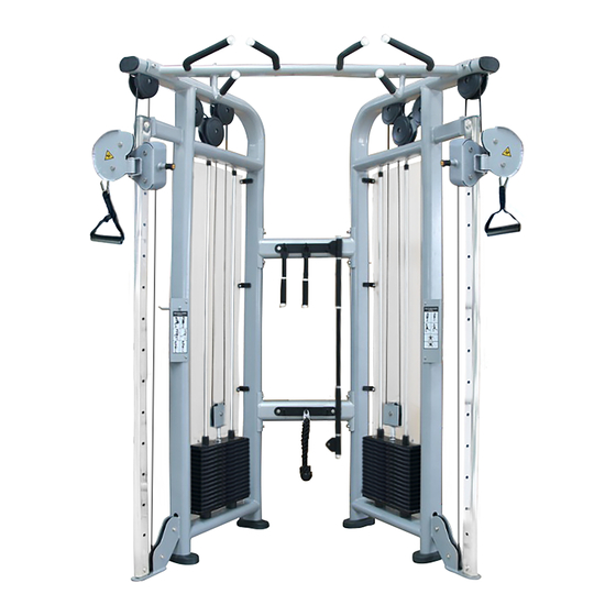
- Page 1 FFS SILVER AND FFB BLACK DUAL ADJUSTABLE PULLEY ASSEMBLY MANUAL...
-
Page 2: Warranty
FEATURES • 11-gauge, 2.5" x 4.5" flat oval steel tube • Nylon-coated cable meets U.S. military specifications • Fiberglass-impregnated nylon pulleys feature sealed bearings • Grips retained with aluminum collars, preventing them from slipping during use • Hand grips are a durable urethane composite TECH SPECS •... -
Page 3: Before You Begin
BEFORE YOU BEGIN Thank you for selecting the DUAL ADJUSTABLE PULLEY. For your safety and benefit, read this manual carefully before using the machine. As a manufacturer, we are committed to provide you complete customer satisfaction. If you have any questions, or find there are missing or damaged parts, we guarantee you complete satisfaction through direct assistance from our factory. -
Page 4: Assembly Instruction
SAVE THESE INSTRUCTIONS. ASSEMBLY INSTRUCTION Tools Required Assembling the Machine: Two Adjustable Wrenches, two Allen Wrenches, and one Philips Screwdriver. NOTE: It is strongly recommended this machine to be assembled by two or more people to avoid possible injury. STEP 1 (See Diagram 1) A.)Slide the Cable Adjustment Assembly(#3)onto the Front Vertical Frame(#2).Insert the Lock Knob(#5) into the Cable Adjustment Assembly(#3). - Page 5 STEP 2 (See Diagram 2) A.)Attach the Cross Support(#11)to the Main Frame(#1).Secure it with Bolt M10x120(#15),∅ 10 Washer(#8),M10 Aircraft Nut(#9). B.)Attach the Pull Down Assembly(#10) to the Main Frame(#1).Secure it with Bolt M10x120(#15),∅ 10 Washer(#8),M10 Aircraft Nut(#9). C.)Attach the Accessories Hanging Plate(#12) to the Cross Support(#11). Secure it with Bolt M10x120(#15),∅...
- Page 6 STEP 3 (See Diagram 3) A.)Insert the Guide Rod(#17) into the holes of Main Frame(#1).Slide the Rubber Bumper onto the Guide Rod(#17). B.)Sloping the top of Guide Rod(#17).Then slide the weight stack(#20) onto the Guide Rod(#17).Attach the Guide Rod(#17)onto the Main Frame(#1).
- Page 7 STEP 4 (See Diagram 4) A.)Assemble the Cable(#23) based on the below cable loop diagram. Secure it with Bolt M6X15(#25)after finishing cable assembly. B.)Attach the Handle(#22) to the Cable(#23) with C-clip(#21). C.)Tighten all the bolts and nuts hard. DIAGRAM 4...
- Page 8 Training Instruction...
Need help?
Do you have a question about the FFS and is the answer not in the manual?
Questions and answers