Advertisement
Quick Links
Advertisement

Subscribe to Our Youtube Channel
Related Manuals for FRENCH FITNESS MSC8


Summary of Contents for FRENCH FITNESS MSC8
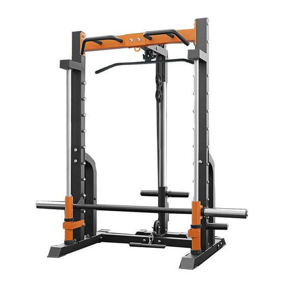
- Page 1 MSC8 MULTI SMITH CABLE MACHINE ASSEMBLY MANUAL...
- Page 2 ...
-
Page 3: Important Safety Instructions
1. IMPORTANT SAFETY INSTRUCTIONS WARNING - Read all instructions before using this machine. Install the product on a flat level surface • Place your unit on a solid, level surface when in use • Never allow children on or near the machine. •... -
Page 4: Care Instructions
2. CARE INSTRUCTIONS Lubricate moving joints with silicon spray after periods of usage. • Be careful not to damage plastic or metal parts of the machine with heavy or sharp • objects. The machine can be kept clean by wiping it down using dry cloth. •... -
Page 5: Parts List
3. PARTS LIST... - Page 7 Step must be completed prior to installing. Failure to do so can leave residue from packaging and other sources stuck in the bushings Guide rods need to make sure they are cleaned prior to installation otherwise this will cause the top plate to get stuck.
- Page 8 4. ASSEMBLY INSTRUCTIONS NOTE: 1. Gaskets shall be placed at both ends of the bolt (against bolt head and nut), as otherwise stated. 2. The initial assembly is to tighten all bolts and nuts by hand, and to tighten them with wrenches when fully assembled.
- Page 9 STEP 2 1. According to the diagram, the left and right insurance (#5), (#6) and the shock absorber (#21) are installed on the Smith guide rod (#3), respectively. 2. Install the slide sleeve (#7) on the horizontal push hook (#4) and install the installed horizontal push hook (#4) on the Smith guide rod (#3).
- Page 10 STEP 3 1. Install the solid short hanging rod (#18) on the left and right column (#10). 2. Connect the left and right columns (#10), (#9) to the Smith guide rod (#3) and the floor (#1) according to the diagram and fasten them with bolts (#23) flat gaskets (#32). 3.
- Page 11 STEP 4 1. Install the left and right handle (#12), (#13) into the upper connection (#11), fasten it with bolt (#24) and flat gasket (#32). 2. Install the upper connection (#11) into the left and right columns (#9) (#10) and fix it with bolt (#25), flat gasket (#32) and nut (#31).
- Page 12 STEP 5 1. Connect the rear floor (#15) with the rear connection (#2) and fix it with bolt (#23), flat gasket (#32) and nut (#15). 2. Install the rear pillar (#14) to the rear patch (#15) as shown and secure with the bolt (#23), (#32) and nut (#31).
- Page 13 STEP 6 1. According to the diagram, the upper beam is mounted on the rear column (# 14) and the upper connection (# 11), the bolt (# 23), flat gasket (# 32) and nut (# 31) are fixed for the connection with the rear column (# 14).
- Page 14 STEP 7 1. Install the Wire rope according to line diagram drawing. 2. After the whole instrument is assembled, check that the wire rope is tightened. If the wire rope is loose, adjust the pulley installation hole position through the pulley regulating plate (# 28). 3.
Need help?
Do you have a question about the MSC8 and is the answer not in the manual?
Questions and answers