Table of Contents
Advertisement
Quick Links
BA6214
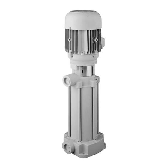
BRINKMANN Pressure Boosting Pumps
BRINKMANN PUMPS, Inc.
47060 Cartier Drive
Wixom, MI 48393
USA
Phone: +1 248 926 9400
Fax.:
+1 248 926 9405
Subject to change without prior notice.
Brinkmann Pumps, Inc.
Operating Instructions
08/2015
Edition
FH11...FH17
www.brinkmannpumps.com
sales@brinkmannpumps.com
Order - No.: BA6214 ENGLISH
Page 1 of 13
Advertisement
Table of Contents

Related Manuals for BRINKMANN PUMPS FH11 Series


Summary of Contents for BRINKMANN PUMPS FH11 Series
- Page 1 BRINKMANN PUMPS, Inc. 47060 Cartier Drive Wixom, MI 48393 Phone: +1 248 926 9400 www.brinkmannpumps.com Fax.: +1 248 926 9405 sales@brinkmannpumps.com Subject to change without prior notice. Order - No.: BA6214 ENGLISH Brinkmann Pumps, Inc. 08/2015 Page 1 of 13 Edition...
-
Page 2: Table Of Contents
Brinkmann Pressure Boosting Pumps series FH11 ... FH17 Contents Indication to the manual ........2 8 Servicing and Maintenance ....... 8 Description of the Product ......2-5 9 Troubleshooting Guide ........9 Safety instructions ..........6 10 Spare Parts ..........10-11 Transportation and Storage ....... - Page 3 Technical data Max. del. Max. del. Height Length Weight Power Noise pressure volume level spec. weight 1 60 Hz Type l/min Inches Inches FH1102S18 24.2 86.0 1.75 FH1103S18 25.2 94.8 FH1104S28 29.4 12.1 103.6 31.5 12.1 125.7 FH1105S28 FH1106S28 10.1 31.5 12.1 132.3...
- Page 4 Max. del. Max. del. Height Length Weight Power Noise pressure volume level spec. weight 1 60 Hz Type l/min Inches Inches FH1402S18 25.6 97.0 2.6 66 31.5 12.1 132.3 4.0 74 FH1403S28 FH1404S28 33.0 12.1 5.5 74 FH1405S38 10.2 40.9 1040 15.9 11.5...
- Page 5 Max. del. Max. del. Height Length Weight Power Noise pressure volume level spec. weight 1 60 Hz Type l/min Inches Inches FH1702S18 27.8 54.5 3.3 72 33.0 12.1 76.5 5.0 74 FH1703S28 FH1704S28 37.1 12.1 11.5 8.6 77 FH1705S38 10.8 40.9 1040 15.9...
-
Page 6: Safety Instructions
3 Safety instructions Safety instructions relevant for operation When operating the pump, the safety instructions If hot or cold machine components involve haz- contained in this manual, the relevant national acci- ards, they must be guarded against accidental dent prevention regulations and any other service and contact. -
Page 7: Installation And Connection
5 Installation and Connection Electric wiring Mechanical installation During any assembly or disassembly process the pumps must be secured against tipping trough ropes for example at all times. All service work must be carried out by qualified Pumps must be mounted securely. Piping, tank and service personnel. -
Page 8: Start-Up / Shut-Down
6 Start-up / Shut-down Start-up ATTENTION If the pump should lock up and cease, shut pump down Switch off at the mains. (see 6.2) and disconnect from power supply. Pump After connection the electrical wires, close the termi- must be uninstalled and removed from the system prior nal box. -
Page 9: Troubleshooting Guide
9 Troubleshooting Guide Fault Cause Remedy Motor does not start, no motor At least two of the power supply Check fuses, terminals and supply noise leads have failed leads . Overload has tripped Inspect overload Motor does not start, humming One of the supply leads has failed See above noise... -
Page 10: Spare Parts
10 Spare Parts 10.1 Spare part list for Pressure Boosting Pumps FH1702S18...FH1706S38 Series FH11, FH1402S18...FH1408S47 Item Description Stator with terminal board Motor flange End shield Motor shaft with rotor Terminal box up to 5.4 HP Terminal box frame from 6.7 HP and over Terminal box cover from 6.7 HP and over Fan cover 10 Gasket... - Page 11 10.2 Spare part list for the pressure boosting pumps series FH1707S47...FH1711S66 FH1409S57...FH1412S66 Item Description Motor Bearing housing Bearing shaft Woodruff key DIN 6888 Ball bearing DIN 628 Distance plate Ball bearing DIN 628 Coupling Socket head cap screw DIN 912 10 Threaded pin DIN 705 11 Bearing cover...
-
Page 12: Repair
10.3 Indications to the spare part order cides with the key groove of the coupling clamp (69.1). Press the pump shaft (52) toward the motor Spare parts are available from the supplier. and tighten the screws. Standard commercially available parts are to be The distance between the two shaft ends must be purchased in accordance with the model type. -
Page 13: Warranty
13 WARRANTY Brinkmann Pumps, Inc. warrants that the product contained herein conforms to the descrip- tion in Brinkmann's catalog and that if this product shall fail to conform to the description thereof or to any express or implied warranty, Brinkmann shall, upon written notice of such nonconformity within one year of the date of its shipment from BRINKMANN'S plant, repair or replace such non-conforming material at the original point of delivery.
Need help?
Do you have a question about the FH11 Series and is the answer not in the manual?
Questions and answers