Table of Contents
Advertisement
Quick Links
★ Please read and follow all warnings, precautions and instructions before
installation and use.
★ Coming with UPS01-PLUS uninterrupted power supply, this series gate opener
can be powered by AC 100-240V electricity directly. It is allowed to use additional
battery (NOT incl.) and solar panel (optional) as BACK-UP or MAIN power source
with this UPS01-PLUS.
★ Never connect the solar panel to the control board directly to charge the battery.
★ Periodic checks of the opener are required to ensure safe operation.
★ Save this manual.
C030622
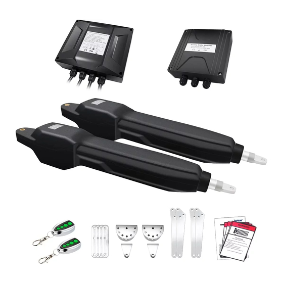
Dual Swing Gate Opener
User's Manual
JY9132
TOPENS Website
www.topens.com
Email: support@topens.com
Model:
VER 23a
Advertisement
Table of Contents

Related Manuals for Topens JY9132


Summary of Contents for Topens JY9132
- Page 1 Dual Swing Gate Opener User’s Manual Model: JY9132 TOPENS Website www.topens.com Email: support@topens.com ★ Please read and follow all warnings, precautions and instructions before installation and use. ★ Coming with UPS01-PLUS uninterrupted power supply, this series gate opener can be powered by AC 100-240V electricity directly. It is allowed to use additional battery (NOT incl.) and solar panel (optional) as BACK-UP or MAIN power source...
- Page 2 Visit: www.topens.com Please record the product model, your email address etc. in the spaces provided below. Refer to this list when contacting TOPENS for technical service or assistance with your automatic gate opener. Where did you purchase? (Amazon.com; Amazon.ca: Amazon.co.uk, Amazon.de; Other, Please...
-
Page 3: Table Of Contents
Extra parts for rounded gate post ......................... 3 Extra Parts for JY9132S ............................ 4 Accessories Parts (Included in some models, refers to the actual package) ...........4 Optional Accessories Parts List (Available at TOPENS Store) ................4 Replacement Parts .............................5 Tools Needed: ..............................5 Technical Specifications &... -
Page 4: Safety Installation Information
use on any pedestrian gate. Pedestrians must be Safety Installation Information supplied with a separate pedestrian access. 1. READ and FOLLOW all instruction. For an installation utilizing non-contact sensors The gate opener is intended for use with Class I (safety sensors), see product manual on vehicular swing gates. - Page 5 BEFORE digging. NOTE: TOPENS Gate Operator can be used for driveway gates made by steel, wood, vinyl, and shaped as panel, tube, and chain-link. While use on solid surface gates is NOT recommended. Solid surface gates have a...
-
Page 6: Parts List
Parts List Extra parts for rounded gate post... -
Page 7: Extra Parts For Jy9132S
Accessories Parts (Included in some models, refers to the actual package) JD24VY 24V Warning TC102 Photo Eye Beam 25FT Extension Light Sensor 5 Conductor Cable Optional Accessories Parts List (Available at TOPENS Store) TC186-R WiFi TC188 Universal ERM12 External M12 Remote Control Smartphone Remote Wireless and Wired... -
Page 8: Replacement Parts
JY9132 Arm Actuator Gate Opener UPS01-PLUS Uninterrupted Power Supply WARNING: Changes or modifications not expressly specified by this user manual, TOPENS could void the warranty of this equipment. Tools Needed: ·Power Drill ·Tape Measure ·Open End Wrenches - 14# &17# or Adjustable Wrenches ·Wire Strippers... -
Page 9: Technical Specifications & Features
Motor Voltage: 24VDC Power: 2×100W Current: Actuator Speed: 16mm/s(0.6 in/s) Max. Actuator Travel: 490mm(19.3 in) Ambient Temperature: -20℃~ +50℃ (0°F to 120°F) Protection Class: IP44 Gate Capacity of JY9132 600kg(1300lbs) √ 500kg(1100lbs)) √ √ 400kg(880lbs)) √ √ √ 300kg(660lbs) √ √... -
Page 10: Installation Overview
Installation Overview Important: The second gate opener cable should be put into the PVC conduit (not provided) which is buried underground .This protects the cable from lawn mowers and string trimmers. -
Page 11: Preparation For Installation
Preparation for Installation There are two installation types for the gate opener, Pull-to-Open and Push-to-Open. In the Push-to-Open installation, gate opens out from the property. A Push-To-Open Bracket is required to be used for each gate. NOTE: Ensure the gate does not open into public areas. One more person will help when installing. The gate opener can be either installed on square gate post or rounded gate post. - Page 12 1. Insert two M10X100 bolts through the holes of post bracket and two pull-to-open brackets as shown. Place bushings in the middle , washers and nuts on the bottom of the bolts and tighten. 2. Attach the gate bracket and post bracket assy. to the opener by inserting a clevis pin.
- Page 13 5. Sign the bolt-hole point on the gate post and gate. Do this by placing a punch or a sign in the middle of each bolt slot on the post bracket and the gate bracket. Then remove the opener and brackets assy. by taking off the C-clamps.
-
Page 14: Install The Opener On The Gate - For Push To Open
9. With the opener fully retracted and with the gate in the fully open position (for Pull-to-Open installation), insert a clevis pin through the gate opener and the pull-to-open Bracket and insert another clevis pin through the gate opener and the Gate Bracket. - Page 15 1. Insert three M10X100 bolts through the holes of post bracket and two push-to-open brackets as shown. Place bushings in the middle , washers and nuts on the bottom of the bolts and tighten. 2. Attach the gate bracket and post bracket assy. to the opener by inserting a clevis pin.
- Page 16 5. Sign the bolt-hole point on the gate post and gate. Do this by placing a punch or a sign in the middle of each bolt slot on the post bracket and the gate bracket. Then remove the opener and brackets assy. by taking off the C-clamps.
- Page 17 9. With the opener fully retracted and with the gate in the fully closed position (for Push-to-Open installation), insert a clevis pin through the gate opener and the push to open bracket and insert another clevis pin through the gate opener and the Gate Bracket. Secure each clevis pin with a hairpin clip. NOTE: The setting of the PULL/PUSH TO OPEN of the control board should be in accordance with the installation.
-
Page 18: Mounting Of The Control Box
Mounting of the Control Box Use 4 deck screws (not provided) to install the control box. Even though the control box is waterproof designed, for safety reason and a longer service life, it is recommended to install the control box inside a secure surface and at least 100 cm (40 inches) above the ground to avoid being flooded or buried under snow. - Page 19 Power Mode 2. By AC electricity and back-up batteries, only use the AC electricity to charge the batteries If the AC electricity failure happens rarely (less than 8 hours per day), then you can use minimum 5AH 2*12VDC batteries as back-up power source in case of AC power failure. In this situation, you can connect the UPS01-PLUS to the control box refer to step 1 in this chapter.
- Page 20 Power Mode 3. Use the batteries as the power source, only use the solar panel to charge the batteries If the AC electricity is not available, then you can choose the batteries as the power source and use the solar panel to charge the batteries.
- Page 21 Power Mode 4. By AC electricity and back-up batteries, use the AC electricity and the solar panel to charge the batteries at the same time If you want to use the solar panel and the AC electricity to charge the batteries at the same time, firstly you can connect the UPS01-PLUS power supply &...
-
Page 22: Connection Of The Control Board
Connection of the Control Board 1. Actuator 1 (Master gate, open first & close last) Insert the stripped cable wires into the appropriate terminals on the opener terminals block. The red wire should be inserted into the #15 terminal of “MOTOR1” port, the black wire into the #16 terminal of “MOTOR1” port, the blue wire into “ULMT1”... - Page 23 2. Actuator 2 (Slave gate, close first & open last) The red wire should be inserted into the #20 terminal of “MOTOR2” port, the black wire into the #21 terminal of “MOTOR1” port, the blue wire into “ULMT2” terminal (#22), the green wire into “COM” terminal (#23), and the yellow wire into “DLMT2”...
-
Page 24: How To Program The Remote To The Opener
12. Wired Keypad (24VDC) (optional) The RED wire of the wired keypad should be connected into the “#11” terminal. The BLACK wire of the wired keypad should be connected into the “#5” terminal. The PURPLE wire of the wired keypad should be connected into the “#5” terminal. The BLUE wire of the wired keypad should be connected into the “#4”... -
Page 25: How To Erase All The Remote Codes
Each remote has four buttons, from top to bottom are separately A, B, C and D. You may use this remote to operate as many as 4 sets TOPENS swing gate openers or 1 set TOPENS sliding gate opener and 2 sets TOPENS swing gate openers. -
Page 26: Adjusting The Limit Switch
then press “OK” to confirm to operate the opener. Also you can change the password of the keypad follow the below steps. Press “PIN” and then input the six digits old password and then press ”PIN” again, the CODE LED will be ON. Input the six digits new password and then press the “PIN”... -
Page 27: Setting Of The Control Board
2 For Push-to-Open Installation, adjust the limit switch B to determine the open position: Turn on power to operate the gate opener, then the arm extends to open the gate. If the arm opens over the desired open position, press the remote control to stop the opener. Use a screwdriver to loosen the screw of the limit B, slightly slide the limit switch B inwards. - Page 28 DIP Switch #3: Enable/disable open interval between the master and slave gate opener ON – Open interval is enabled OFF –Open interval is disabled Factory default setting is ON. NOTE: Open interval time can be adjusted by the OPEN DELAY potentiometer. DIP Switch #4: Enable/disable close interval between the master and slave gate opener ON –...
-
Page 29: Maintenance
Maintenance Warning: Disconnect power before servicing. 1. Using a clean, dry cloth to wipe the gate opener shaft, and then apply a silicone spray to reduce its friction. In cold climates where temperatures reach 1°C (30°F) or less, spray silicone on the actuator every 4~6 weeks to prevent freeze up. - Page 30 battery charged above 22VDC. 4. Check the output of UPS01. If the output of UPS01 is measured below 21VDC and the voltage of batteries above 22VDC or the power cord has been plugged into the socket well, then UPS01 is defective. 5.
- Page 31 Flash quickly for 3 1. Ensure the photo beam Both of the gates do Flash quickly for 3 seconds and then is not blocked when a move when seconds and then back flash photocell is used. operating back to OFF slowly(1 Blink every 2.
- Page 32 Your comments and suggestions are important to us as they help us provide the best possible service. Should you have any need to contact us, the info below will help you get in touch: TOPENS Website www.topens.com Contact Us: E-mail: support@topens.com Kindly include your Product Model, Purchasing Date &...
Need help?
Do you have a question about the JY9132 and is the answer not in the manual?
Questions and answers