
Related Manuals for protech PA-J581 Series


Summary of Contents for protech PA-J581 Series
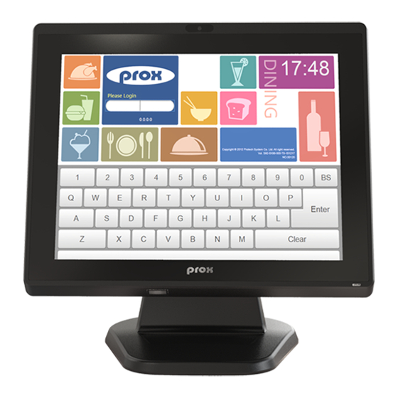
- Page 1 USER MANUAL PA-J581 Series 15” Fanless Slim POS Terminal Powered by Intel Celeron ® ® J6412 CPU Processor PA-J581 M1...
- Page 2 PA-J581 POS System COPYRIGHT NOTICE & TRADEMARK All trademarks and registered trademarks mentioned herein are the property of their respective owners. This manual is copyrighted in Feb. 2023. You may not reproduce or transmit in any form or by any means, electronic, or mechanical, including photocopying and recording.
- Page 3 FCC NOTICE This equipment has been tested and found to comply with the limits for a Class A digital device, pursuant to part 15 of the FCC Rules. These limits are designed to provide reasonable protection against harmful interference when the equipment is operated in a commercial environment.
-
Page 4: Table Of Contents
Contents Revision History ................... vii Introduction ..................1-2 1.1 About This Manual ............... 1-2 1.2 POS System Overview ..............1-3 1.2.1 Panel PC ................1-3 1.2.2 Normal Stand ............... 1-4 1.2.3 Normal Stand with 15” 2nd Display ........1-5 1.2.4 Normal Stand with VFD............ - Page 5 2.2.12 Cash Drawer Port (DRW) ........... 2-11 2.2.13 Line Out Audio Jack (Line-out) ........... 2-12 2.2.14 Mic In Audio Jack (MIC) ............. 2-12 2.3 Main Board Component Locations & Jumper Settings ....2-13 2.4 Jumper & Connector Quick Reference Table ......2-15 2.5 Setting Jumpers .................
- Page 6 2.6.20 EDP Connector (EDP1) ............. 2-39 2.6.21 LVDS Connector (LVDS1) ..........2-40 2.6.22 Slide Switch For LVDS Resolution Selection (SW2) ..2-41 2.6.23 M.2 M-Key Slot (M2_M1) ........... 2-42 2.6.24 M.2 E-Key Slot (M2_E1) ............ 2-44 2.6.25 SATA 3.0 & SATA Power Connectors (SATA1, SATA_PWR1) .....................
- Page 7 3.1 Driver ................... 3-2 3.1.1 Introduction ................3-2 ® 3.1.2 Intel Chipset Software Installation Utility ......3-3 3.1.3 Graphics Driver Utility ............3-4 ® 3.1.4 Intel Management Engine Components Installer Installation ................... 3-5 3.1.5 LAN Driver Utility ..............3-6 3.1.6 Sound Driver Utility ..............
- Page 8 3.5.2 Main..................3-32 3.5.3 Advanced ................3-33 3.5.3.1 Advanced – CPU Configuration ........3-34 3.5.3.2 Advanced – PCH-FW Configuration ......3-36 3.5.3.3 Advanced – Trusted Computing ........3-37 3.5.3.4 Advanced – ACPI Settings ........... 3-38 3.5.3.5 Advanced – F81967 Super IO Configuration ....3-39 3.5.3.6 Advanced –...
- Page 9 Front Cover Module Assembly Exploded Diagram (1) (Flat Resistive Touch Panel) .....................A-19 Front Cover Module Assembly Exploded Diagram (2) ......A-20 Front Cover Module Assembly Exploded Diagram (3) (Projected Capacitive Touch Panel) ...................A-21 Rear Cover Assembly Exploded Diagram (1) .........A-22 Rear Cover Assembly Exploded Diagram (2) .........A-23 LCD Case Assembly Exploded Diagram ..........A-24 Exploded Diagram for Panel PC HDD Assembly ........A-25 LCD Assembly Exploded Diagrams (1) ..........A-26...
-
Page 10: Revision History
Revision History The revision history of PA-J581 User Manual is described below: Version No. Revision History Page No. Date Initial Release 2023/02/21... -
Page 11: Introduction
Introduction This chapter gives you the information for the PA-J581. It also outlines the system specifications. The following topics are included: • About This Manual • POS System Overview • System Specifications • Safety Precautions Experienced users can go to Chapter 2 for a quick start. PA-J581 USER MANUAL Page: 1-1... -
Page 12: About This Manual
Chapter 1 Introduction About This Manual Thank you for purchasing our PA-J581 Series System. The PA-J581 is an updated system designed to be comparable with the highest performance of IBM AT personal computers. The PA-J581 provides faster processing speed, greater expandability and can handle more tasks than before. -
Page 13: Pos System Overview
Chapter 1 Introduction POS System Overview Unit: mm 1.2.1 Panel PC Front View Rear View M4 screw hole (x4) Left Side View Right Side View 58.75 PA-J581 USER MANUAL Page: 1-3... -
Page 14: Normal Stand
Chapter 1 Introduction 1.2.2 Normal Stand Unit: mm Front View Rear View Left Side View Right Side View PA-J581 USER MANUAL Page: 1-4... -
Page 15: Normal Stand With 15" 2Nd Display
Chapter 1 Introduction 1.2.3 Normal Stand with 15” 2nd Display Unit: mm Front View Side View 254.11 Quarter View PA-J581 USER MANUAL Page: 1-5... -
Page 16: Normal Stand With Vfd
Chapter 1 Introduction 1.2.4 Normal Stand with VFD Unit: mm Front View Side View 249.61 Quarter View PA-J581 USER MANUAL Page: 1-6... -
Page 17: System Specifications
Chapter 1 Introduction System Specifications System ® ® CPU Support Intel Celeron J6412 CPU Memory 1 x DDR4 SO-DIMM (up to 16GB) Network Gigabit 10/100/1000 Base-T Fast Ethernet Power Supply 60W/90W power adapter ® ® O.S. Support Windows 10 IoT Enterprise / Windows 11 IoT Enterprise Audio 2W speaker... - Page 18 Chapter 1 Introduction • 1D: EEAN-13, EAN-8, UPC-A, UPC-E, ISSN, ISBN, Codabar, Code 128, Code 93, ITF-6, ITF-14, Interleaved 2 of 5, Industrial 2 of 5, Standard 2 of 5, Matrix 2 of 5, GS1 Barcode Scanner Databar, Code 39, Code 11 •...
-
Page 19: Safety Precautions
Chapter 1 Introduction Safety Precautions Before using this system, read the following information carefully to protect your system from damages, and extend the life cycle of the system. Check the Line Voltage • The operating voltage for the power supply should be within the range of 100V to 240V AC;... -
Page 20: System Configuration
System Configuration This chapter contains helpful information that describes the jumper and connector settings, component locations, and pin assignment. The following topics are included: • System External I/O Ports Diagram • Function Button and I/O Ports • Main Board Component Locations & Jumper Settings •... -
Page 21: System External I/O Ports Diagram & Pin Assignment
Chapter 2 System Configuration System External I/O Ports Diagram & Pin Assignment Rear I/O Ports Line Out (option) HDMI Mic (option) DC-IN Connector DC-IN HDMI COM3 COM2 COM1 Line-out 2ND-DIS USB 3/4 USB 1/2 Connector Optional: Extension Type A USB x 1 / Extension RJ45 COM x1 / Extension Power USB 24V x1 PA-J581 USER MANUAL... -
Page 22: Function Button And I/O Ports
Chapter 2 System Configuration Function Button and I/O Ports 2.2.1 Power Button To turn on the system, press the power button on the side of the system briefly. ACTION ASSIGNMENT Click Power Release +3.3V Button 2.2.2 DC-IN Port Port Location: DC-IN Description: DC Power-In Port (rear I/O) ASSIGNMENT ASSIGNMENT... -
Page 23: Extension Rj45 Com Port (Option)
Chapter 2 System Configuration 2.2.4 Extension RJ45 COM Port (option) Port Location: Extension RJ45 COM Port (rear I/O) Description: Extension RJ45 COM Connector The pin assignments are as follows: ASSIGNMENT COM_DCDJ_I COM_RX_I COM_TX_I COM_DTRJ_I COM Port Connector COM_DSRJ_I (option) COM_RTSJ_I COM_CTSJ_I COM_RI_SEL PA-J581 USER MANUAL... -
Page 24: Lan Port (Lan)
Chapter 2 System Configuration 2.2.5 LAN Port (LAN) Port Location: LAN Description: LAN Port The pin assignments are as follows: LAN: a Giga LAN RJ-45 port (rear I/O) Assignment LAN1_MDI0_DP LAN1_MDI0_DN LAN1_MDI1_DP LAN1_MDI1_DN LAN1_MDI2_DP LAN1_MDI2_DN LAN1_MDI3_DP LAN1_MDI3_DN LAN LED Indicator: Orange Color Blinking 1G Giga LAN Message Active Green Color Blinking... -
Page 25: Hdmi Port Connector (Hdmi)
Chapter 2 System Configuration 2.2.6 HDMI Port Connector (HDMI) Port Location: HDMI Description: HDMI Connector (rear I/O) HDMI ASSIGNMENT ASSIGNMENT HDMI_P2 HDMI_N2 HDMI_P1 HDMI_N1 HDMI_P0 HDMI_N0 HDMI_CLKP HDMI_CLKN HDMI_SCL_5V HDMI_SDA_5V V5P0S_HDMI HDMI_HPD PA-J581 USER MANUAL Page: 2-6... -
Page 26: Dual Usb 3.0 Port Connector (Usb1, Usb2)
Chapter 2 System Configuration 2.2.7 Dual USB 3.0 Port Connector (USB1, USB2) Port Location: USB1, USB2 Description: Dual USB 3.0 Type A Connector (rear I/O) The pin assignments are as follows: USB1 / USB2 (USB 3.0) USB 3.0 signals: ASSIGNMENT ASSIGNMENT USB_PWR1 USB_PWR2... -
Page 27: Dual Usb 2.0 Port Connector (Usb3, Usb4)
Chapter 2 System Configuration 2.2.8 Dual USB 2.0 Port Connector (USB3, USB4) Port Location: USB3, USB4 Description: USB 2.0 Type A Connector (rear I/O) The pin assignments are as follows: ASSIGNMENT ASSIGNMENT USB_PWR3 USB_PWR4 USB2_P3_DN_CL USB2_P4_DN_CL USB2_P3_DP_CL USB2_P4_DP_CL USB3 / USB4 (USB 2.0) PA-J581 USER MANUAL Page: 2-8... -
Page 28: Power Port Connector (24V Pwr)
Chapter 2 System Configuration 2.2.9 24V Power Port Connector (24V PWR) Port Location: 24V PWR Description: 24V Power Port Connector The pin assignments are as follows: ASSIGNMENT ASSIGNMENT 24V PWR 2.2.10 2nd Display Power Port Connector (2ND-DIS PWR) Port Location: 2ND-DIS PWR Description: 2nd Display Power Port Connector The pin assignments are as follows: ASSIGNMENT... -
Page 29: Extension Power Usb 24V Port / Dual Usb 2.0 Port
Chapter 2 System Configuration 2.2.11 Extension Power USB 24V Port / Dual USB 2.0 Port (option) Port Location: Extension Power USB 24V Port (option) Description: 24V Power USB Port (rear I/O) ASSIGNMENT ASSIGNMENT USB D- +24V USB D+ +24V 24V Power USB (option) Connector Location: Extension Dual USB 2.0 Connector (option) Description: Extension Dual USB 2.0 Connector (rear I/O) -
Page 30: Cash Drawer Port (Drw)
Chapter 2 System Configuration 2.2.12 Cash Drawer Port (DRW) Port Location: DRW Description: RJ-11 Cash Drawer Connector (+12V/+24V selectable, default: +12V). DRW1 is used by default. The pin assignments are as follows: ASSIGNMENT GND / DRW2_OPEN DRW1_OPEN DRW1_SEN PWR_CASH1 DRW2_SEN PA-J581 USER MANUAL Page: 2-11... -
Page 31: Line Out Audio Jack (Line-Out)
Chapter 2 System Configuration 2.2.13 Line Out Audio Jack (Line-out) Connector Location: Line-out Description: Line Out Audio Jack ASSIGNMENT HD_LINE-OUT-R Line-out HD_LINE-OUT-L 2.2.14 Mic In Audio Jack (MIC) Connector Location: MIC Description: Mic In Audio Jack ASSIGNMENT HD_MIC1-L HD_MIC1-R PA-J581 USER MANUAL Page: 2-12... -
Page 32: Main Board Component Locations & Jumper Settings
Chapter 2 System Configuration Main Board Component Locations & Jumper Settings M/B: PB-J581 DC_IN1 DRW1 USB2 USB1 LAN1 HDMI1 COM3_1 COM1 COM2_1 COM2_2 COM3_2 USB3_2 USB4_2 JP_COM3 JP_COM2 JP_COM1 JP_USB3 SATA1 VOUT_24 USB7 JP_USB4 VOUT_12 M.2 E key JP_USB7 M.2 M key M2_E1 USB5 M2_M1... - Page 33 Chapter 2 System Configuration WARNING: Always disconnect the power cord when you are working with the connectors and jumpers on the main board. Make sure both the system and the external devices are turned OFF as sudden surge of power could ruin sensitive components.
-
Page 34: Jumper & Connector Quick Reference Table
Chapter 2 System Configuration Jumper & Connector Quick Reference Table JUMPER NAME Clear CMOS Data Selection JCMOS1 COM Port RI & Voltage JP_COM1, JP_COM2, JP_COM3 Selection USB3 Port Selection JP_USB3 USB4 Port Selection JP_USB4 USB5 Port Selection JP_USB5 USB7 Port Selection JP_USB7 USB8 / M.2 Selection JP_USB8... - Page 35 Chapter 2 System Configuration SYSTEM CONNECTOR NAME DC-IN Port (rear I/O) DC-IN 24V Power Port (rear I/O) 24V PWR 2nd Display Power Port 2ND-DIS PWR Connector (rear I/O) (option) Line Out and Mic In Line-out, MIC Audio Jack (rear I/O) COM Port Connector (rear I/O) COM1, COM2, COM3 Extension RJ45 COM Port...
- Page 36 Chapter 2 System Configuration SYSTEM CONNECTOR NAME Battery Wafer JBAT1 Panel Inverter Wafer INV1 Speaker Wafer SPK1 Audio Codec Line Out / AUDIO1 Mic Pin Header LVDS Connector LVDS1 HDMI Port Connector (rear I/O) HDMI EDP Connector EDP1 Power Button Wafer JPWRBTN1 System Reset Wafer JRST1...
-
Page 37: Setting Jumpers
Chapter 2 System Configuration Setting Jumpers You can configure your board by setting the jumpers. A jumper consists of two or three metal pins with a plastic base mounted on the card. By using a small plastic "cap", also known as the jumper cap (with a metal contact inside), you are able to connect the pins. - Page 38 Chapter 2 System Configuration Jumper Diagrams Jumper Settings PA-J581 USER MANUAL Page: 2-19...
-
Page 39: Setting Main Board Connectors And Jumpers
Chapter 2 System Configuration Setting Main Board Connectors and Jumpers 2.6.1 COM1, COM2_1, COM3_1 Voltage Selection (JP_COM1, JP_COM2, JP_COM3) Jumper Location: JP_COM1, JP_COM2, JP_COM3 Description: COM1, COM2_1, COM3_1 voltage are set by jumpers on board. SELECTION JUMPER SETTING JUMPER ILLUSTRATION JP_COM1/ (Default Setting) JP_COM2/... -
Page 40: Com4 Connector (Com4)
Chapter 2 System Configuration 2.6.2 COM Connectors (COM2_2, COM3_2) Connector Location: COM2_2, COM3_2 Description: COM Connectors ASSIGNMENT ASSIGNMENT COM2/3_DCDJ_I COM2/3_DSRJ_I COM2/3_RX_I COM2/3_RTSJ_I COM2/3_TX_I COM2/3_CTSJ_I COM2_2 / COM2/3_DTRJ_I COM2/3_RI_SEL COM3_2 2.6.3 COM4 Connector (COM4) Connector Location: COM4 Description: COM4 Connector ASSIGNMENT ASSIGNMENT COM4_DCDJ_I COM4_DSRJ_I... -
Page 41: Lvds Vcc Voltage Selection (Jp1)
Chapter 2 System Configuration 2.6.4 LVDS VCC Voltage Selection (JP1) Jumper Location: JP1 Description: LVDS VCC Voltage Selection SELECTION JUMPER SETTING JUMPER ILLUSTRATION 3.3V (Default Setting) PA-J581 USER MANUAL Page: 2-22... -
Page 42: Lvds Bklctl Pwm Voltage Level Selection (Jp2)
Chapter 2 System Configuration 2.6.5 LVDS BKLCTL PWM Voltage Level Selection (JP2) Jumper Location: JP2 Description: LVDS BKLCTL PWM Voltage Level Selection SELECTION JUMPER SETTING JUMPER ILLUSTRATION 3.3V (Default Setting) JP4 Select Open PA-J581 USER MANUAL Page: 2-23... -
Page 43: Lvds Bklctl Pwm Fix Voltage Selection (Jp4)
Chapter 2 System Configuration 2.6.6 LVDS BKLCTL PWM Fix Voltage Selection (JP4) Jumper Location: JP4 Description: LVDS BKLCTL PWM Fix Voltage Selection SELECTION JUMPER SETTING JUMPER ILLUSTRATION Open JP2 Select (Default Setting) PA-J581 USER MANUAL Page: 2-24... -
Page 44: Ldvs Bklctl Pwm Selection (Jp5)
Chapter 2 System Configuration 2.6.7 LDVS BKLCTL PWM Selection (JP5) Jumper Location: JP5 Description: LDVS BKLCTL PWM Selection SELECTION JUMPER SETTING JUMPER ILLUSTRATION SOC PWM (Default Setting) 7511 PWM 2.6.8 LVDS BKLTEN Voltage Level Selection (JP6) Jumper Location: JP6 Description: LVDS BKLTEN Voltage Level Selection SELECTION JUMPER SETTING JUMPER ILLUSTRATION... -
Page 45: Drawer Ports (Drw1, Drw1-1, Drw1-2)
Chapter 2 System Configuration 2.6.9 Drawer Ports (DRW1, DRW1-1, DRW1-2) Connector Location: DRW1, DRW1-1, DRW1-2 Description: DRW1 is used by default. If you need a second port, adopt either way as below: Step 1: Set JP7 to DRW1-1 & DRW1-2 or DRW1 only. -
Page 46: Cash Drawer Voltage Selection (Jp3)
Chapter 2 System Configuration DC-IN HDMI COM3 COM2 COM1 Line-out 2ND-DIS USB 3/4 USB 1/2 DRW1 DRW1-1 Step 3: DRW1, DRW1-1, DRW1-2 shares the same power source. 2.6.11 Cash Drawer Voltage Selection (JP3) Jumper Location: JP3 Description: Cash Drawer Voltage Selection JUMPER JUMPER SELECTION... - Page 47 Chapter 2 System Configuration Cash Drawer CONFIGURATION The I/O port address is 2E (hex) and 2F (hex). 2E (hex) is the address port. 2F (hex) is the data port. User must first assign the address of register by writing address value into address port 2E (hex), then write/read data to/from the assigned register through data port 2F (hex).
- Page 48 Chapter 2 System Configuration Code example for open the cash drawer ; ------------------------- Enter to extended function mode ------------------------------- ; ----------------------- Select Logical Device 6 of Cash Drawer --------------------- ;---------------------------------Open the Cash Drawer ------------------------------ ;---------------------------------Close the Cash Drawer ------------------------------ ;---------------------------------Exit the extended function mode ------------------------- PA-J581 USER MANUAL Page: 2-29...
-
Page 49: Usb3 Port Selection (Jp_Usb3)
Chapter 2 System Configuration 2.6.12 USB3 Port Selection (JP_USB3) Jumper Location: JP_USB3 Description: USB3 Port Selection JUMPER JUMPER SELECTION SETTING ILLUSTRATION 1-3, USB3 (Default Setting) JP_USB3 3-5, USB3_2 JP_USB3 2.6.13 USB4 Port Selection (JP_USB4) Jumper Location: JP_USB4 Description: USB4 Port Selection JUMPER JUMPER SELECTION... -
Page 50: Usb5 Port Selection (Jp_Usb5)
Chapter 2 System Configuration 2.6.14 USB5 Port Selection (JP_USB5) Jumper Location: JP_USB5 Description: USB5 Port Selection JUMPER JUMPER SELECTION SETTING ILLUSTRATION 1-3, USB5 (Default Setting) JP_USB5 3-5, USB5_2 JP_USB5 2.6.15 USB7 Port Selection (JP_USB7) Jumper Location: JP_USB7 Description: USB7 Port Selection JUMPER JUMPER SELECTION... -
Page 51: Usb8 / M.2 Selection (Jp_Usb8)
Chapter 2 System Configuration 2.6.16 USB8 / M.2 Selection (JP_USB8) Jumper Location: JP_USB8 Description: USB8 / M2_M1 Selection JUMPER JUMPER SELECTION SETTING ILLUSTRATION 1-3, M2_M1 (Default Setting) JP_USB8 3-5, USB8 JP_USB8 PA-J581 USER MANUAL Page: 2-32... -
Page 52: Usb5 Connector (Usb5)
Chapter 2 System Configuration 2.6.17 USB5 Connector (USB5) Connector Location: USB5 Description: USB 2.0 Type A Connector (side I/O) USB 2.0 signals: ASSIGNMENT USB_PWR5 USB2_P5_DN_CL USB2_P5_DP_CL USB5 PA-J581 USER MANUAL Page: 2-33... -
Page 53: Internal Usb Wafers
Chapter 2 System Configuration 2.6.18 Internal USB Wafers (USB3_2, USB4_2, USB5_2, USB6, USB7, USB8, USB9, USB10) Wafer Location: USB3_2, USB4_2, USB5_2, USB6, USB7, USB8, USB9, USB10 USB3_2 Description: Internal USB wafer USB2 option ASSIGNMENT USB_PWR3 USB2_P3_DN_HL USB2_P3_DP_HL USB3_2 USB4_2 Description: Internal USB wafer USB4 option ASSIGNMENT USB_PWR4 USB2_P4_DN_HL... - Page 54 Chapter 2 System Configuration USB6 Description: Internal USB wafer ASSIGNMENT USB_PWR6 USB2_P6_DN_C USB2_P6_DP_C USB6 USB7 Description: Internal USB wafer Touch option ASSIGNMENT USB_PWR7 USB2_P7_DN_HL USB2_P7_DP_HL USB7 PA-J581 USER MANUAL Page: 2-35...
- Page 55 Chapter 2 System Configuration USB8 Description: Internal USB wafer M2_M1 option ASSIGNMENT USB_PWR8 USB2_P8_DN_HL USB2_P8_DP_HL USB8 USB9 Description: Internal USB wafer ASSIGNMENT USB_PWR9 USB2_P9_DN USB2_P9_DP USB9 PA-J581 USER MANUAL Page: 2-36...
- Page 56 Chapter 2 System Configuration USB10 Description: Internal USB wafer ASSIGNMENT USB_PWR10 USB2_P10_DN USB2_P10_DP USB10 PA-J581 USER MANUAL Page: 2-37...
-
Page 57: Vga Connector (Jvga1)
Chapter 2 System Configuration 2.6.19 VGA Connector (JVGA1) Connector Location: JVGA1 Description: VGA Connector ASSIGNMENT ASSIGNMENT CRT_RED_LL CRT_GREEN_LL CRT_BLUE_LL SPC_R CRT_VCC_L SPD_R CRT_DDC_DATA_O CRT_HSYNC_O CRT_VSYNC_O CRT_DDC_CLK_O JVGA1 PA-J581 USER MANUAL Page: 2-38... -
Page 58: Edp Connector (Edp1)
Chapter 2 System Configuration 2.6.20 EDP Connector (EDP1) Connector Location: EDP1 Description: EDP Connector EDP1 ASSIGNMENT EDP_DCR_EN DDIA_TX1_DN_EDP DDIA_TX1_DP_EDP DDIA_TX0_DN_EDP DDIA_TX0_DP_EDP DDIA_AUX_DP_EDP DDIA_AUX_DN_EDP LVDS_VCC LVDS_VCC EDP_SELF_TEST EDP_HPD_R SOC_BKLTEN_EDP SOC_BKLTCTL_EDP PA-J581 USER MANUAL Page: 2-39... -
Page 59: Lvds Connector (Lvds1)
Chapter 2 System Configuration 2.6.21 LVDS Connector (LVDS1) Connector Location: LVDS1 Description: LVDS Connector LVDS1 ASSIGNMENT ASSIGNMENT LVDS_VCC LVDS_CLKB_DN LVDS_CLKB_DP LVDS_B2_DN LVDS_B2_DP LVDS_B1_DN LVDS_B1_DP LVDS_B3_DP LVDS_B3_DN LVDS_B0_DP LVDS_B0_DN LVDS_CLKA_DP LVDS_CLKA_DN LVDS_A2_DP LVDS_A2_DN LVDS_A1_DP LVDS_A1_DN LVDS_A0_DP LVDS_A0_DN LVDS_A3_DP LVDS_A3_DN LVDS_VCC LVDS_VCC PA-J581 USER MANUAL Page: 2-40... -
Page 60: Slide Switch For Lvds Resolution Selection (Sw2)
Chapter 2 System Configuration 2.6.22 Slide Switch For LVDS Resolution Selection (SW2) Switch Location: SW2 Description: Slide Switch for LVDS Resolution/Channel/Color Bit Selection Resolution Channel 6 or 8 bit 1280x800 1024x768 1024x768 (Default) 1280x768 1280x800 1280x960... - Page 61 Chapter 2 System Configuration 2.6.23 M.2 M-Key Slot (M2_M1) Connector Location: M2_M1 M.2 M-Key Connector for SSD Description: M2_M1 ASSIGNMENT ASSIGNMENT V3P3S_M2_CPU V3P3S_M2_CPU M2_LED1 V3P3S_M2_CPU V3P3S_M2_CPU V3P3S_M2_CPU V3P3S_M2_CPU PCIE4_RX_N1 PCIE4_RX_P1 PCIE4_TX_N1 PCIE4_TX_P1 PCIE4_RX_N0_SATA1_RXP PA-J581 USER MANUAL Page: 2-42...
- Page 62 Chapter 2 System Configuration ASSIGNMENT ASSIGNMENT PCIE4_RX_P0_SATA1_RXN PCIE4_TX_N0_SATA1_TXN PCIE4_TX_P0_SATA1_TXP M2_KEYM_CPU_SSD_RST_R_N GPPC_D5_SRCCLKREQ0_N CLK_SRC0_DN WAKE_N CLK_SRC0_DP M_KEY M_KEY M_KEY M_KEY PCIE_SEL V3P3S_M2_CPU V3P3S_M2_CPU V3P3S_M2_CPU Note: M.2 M-key slot supports SATAIII only. PA-J581 USER MANUAL Page: 2-43...
- Page 63 Chapter 2 System Configuration 2.6.24 M.2 E-Key Slot (M2_E1) Connector Location: M2_E1 M.2 E-Key Connector for Wi-Fi Description: M2_E1 ASSIGNMENT ASSIGNMENT V3.3A_WLAN M_USB2_P10_DP V3.3A_WLAN M_USB2_P10_DN M.2_WLAN_LED1_N AVS_I2S2_SCLK_R AVS_I2S2_SFRM AVS_I2S2_RXD AVS_I2S2_TXD M.2_BT_LED2_N UART_BT_WAKE_N SIO_UART0_RXD E-KEY E-KEY E-KEY E-KEY E-KEY E-KEY E-KEY E-KEY SIO_UART0_TXD SIO_UART0_CTS...
- Page 64 Chapter 2 System Configuration ASSIGNMENT ASSIGNMENT PCIE_CLKREQ1_N GPPC_A13_BT_RF_KILL_N GPPC_C23_WIFI_WAKE_N GPPC_B15_WIFI_RF_KILL_N TP11 V3.3A_WLAN V3.3A_WLAN PA-J581 USER MANUAL Page: 2-45...
- Page 65 Chapter 2 System Configuration 2.6.25 SATA 3.0 & SATA Power Connectors (SATA1, SATA_PWR1) Connector Location: SATA1 Description: Serial ATA 3.0 Connector ASSIGNMENT SATA_TXP0 SATA_TXN0 SATA1 SATA_RXN0 SATA_RXP0 Connector Location: SATA_PWR1 Description: SATA Power Wafer ASSIGNMENT SATA_PWR1 PA-J581 USER MANUAL Page: 2-46...
-
Page 66: General-Purpose Input / Output Connector (Gpio1)
Chapter 2 System Configuration 2.6.26 General-Purpose Input / Output Connector (GPIO1) Connector Location: GPIO1 Description: General-Purpose Input / Output Connector ASSIGNMENT DIO1 DIO2 3.3V GPIO1 2.6.27 On Board Touch Wafer (JTOUCH1) Connector Location: JTOUCH1 On Board Touch Wafer Description: ASSIGNMENT JTOUCH1 PA-J581 USER MANUAL Page: 2-47... - Page 67 Chapter 2 System Configuration 2.6.28 24V DC Out Connector (VOUT_24) Connector Location: VOUT_24 Description: 24V DC Out Connector ASSIGNMENT VOUT_24 2.6.29 Power for 2nd Display Connector (VOUT_12) Connector Location: VOUT_12 Power for 2nd Display Connector Description: ASSIGNMENT VOUT_12 PA-J581 USER MANUAL Page: 2-48...
-
Page 68: Dc 5V Power Connector (Vout_5)
Chapter 2 System Configuration 2.6.30 DC 5V Power Connector (VOUT_5) Connector Location: VOUT_5 DC 5V Power Connector Description: ASSIGNMENT VOUT_5 2.6.31 Power Button Wafer (JPWRBTN1) Connector Location: JPWRBTN1 Power Button Wafer Description: ASSIGNMENT PWRBTN_N JPWRBTN1 PA-J581 USER MANUAL Page: 2-49... -
Page 69: System Led Wafer (Jsys_Led1)
Chapter 2 System Configuration 2.6.32 System LED Wafer (JSYS_LED1) Connector Location: JSYS_LED1 System LED Wafer Description: ASSIGNMENT SYS_LED JSYS_LED1 2.6.33 Audio Connector (AUDIO1) Connector Location: AUDIO1 Description: Audio Codec Line Out / Mic Pin Header ASSIGNMENT ASSIGNMENT HD_MIC1-L HD_MIC1-R AUDIO1 HD_LINE-IN-L HD_LINE-IN-R HD_LINE-OUT-L... -
Page 70: System Reset Wafer (Jrst1)
Chapter 2 System Configuration 2.6.35 CPU Fan Connector (CPU_FAN1) Connector Location: CPU_FAN1 Description: CPU Fan Connector ASSIGNMENT CPU_FANIN CPU_FANOUT Note: PA-J581 is a fanless system. CPU_FAN1 2.6.36 System Reset Wafer (JRST1) Connector Location: JRST1 Description: System Reset Wafer ASSIGNMENT RSTJ_BTN JRST1 PA-J581 USER MANUAL Page: 2-51... -
Page 71: Panel Inverter Wafer (Inv1)
Chapter 2 System Configuration 2.6.37 Panel Inverter Wafer (INV1) Connector Location: INV1 Description: Panel Inverter Wafer ASSIGNMENT LVDS BKLCTL LVDS BKLTEN INV1 2.6.38 I2C Wafer (I2C1) Connector Location: I2C1 Description: I2C Wafer ASSIGNMENT 3.3V I2C_SCL I2C_SDA I2C1 PA-J581 USER MANUAL Page: 2-52... -
Page 72: Battery Wafer (Jbat1)
Chapter 2 System Configuration 2.6.39 Battery Wafer (JBAT1) Connector Location: JBAT1 Description: Battery Wafer ASSIGNMENT VRTC_BATT JBAT1 PA-J581 USER MANUAL Page: 2-53... -
Page 73: Clear Cmos Data Selection (Jcmos1)
Chapter 2 System Configuration 2.6.40 Clear CMOS Data Selection (JCMOS1) Jumper Location: JCMOS1 Description: Clear CMOS data selection SELECTION JUMPER SETTING JUMPER ILLUSTRATION Open Normal (Default Setting) JCMOS1 Clear CMOS Data JCMOS1 Note: To clear CMOS data, you must power off the computer and set the jumper to “Clear CMOS Data”... -
Page 74: Vfd Board Component Locations & Pin Assignment
Chapter 2 System Configuration VFD Board Component Locations & Pin Assignment 2.7.1 VFD Board: MB-4003 Figure 2-1. MB-4003 VFD Board Component Locations 2.7.2 Jumper & Connector Quick Reference Table Jumper / Connector NAME Power Switch Selection JP12V RS-232 Serial Interface Connector PA-J581 USER MANUAL Page: 2-55... -
Page 75: Setting Mb-4003 Vfd Board Connector And Jumper
Chapter 2 System Configuration 2.7.3 Setting MB-4003 VFD Board Connector and Jumper 2.7.3.1 Power Switch Selection (JP12V) Jumper Location: JP12V Description: Power Switch Selection SELECTION JUMPER SETTING JUMPER ILLUSTRATION JP12V (Default Setting) JP12V Open JP12V Note: If CN2 (External Power Switch Connector) is connected with the cable, JP12V (Power Switch Jumper) should not be set (NC). -
Page 76: Software Utilities
Software Utilities This chapter provides the detailed information of driver utilities and BIOS settings for the system. The following topics are included: Driver ® - Intel Chipset Software Installation Utility - Graphics Driver Utility ® - Intel Management Engine Driver Installation - LAN Driver Utility - Sound Driver Utility Embedded Peripheral Devices... -
Page 77: Driver
Chapter 3 Software Utilities Driver 3.1.1 Introduction Enclosed with the PA-J581 Series package is our driver utilities, which comes in a DVD-ROM disc. See the following table for driver locations. Filename (Assume that Purpose DVD- ROM drive is D :) -
Page 78: Intel ® Chipset Software Installation Utility
Chapter 3 Software Utilities ® 3.1.2 Intel Chipset Software Installation Utility Introduction ® The Intel Chipset Software Installation Utility installs to the target system the Windows* INF files that outline to the operating system how the chipset components will be configured. This is required for the following features to function properly: Core PCI and ISAPNP Services •... -
Page 79: Graphics Driver Utility
Chapter 3 Software Utilities 3.1.3 Graphics Driver Utility The Graphics interface embedded with the PA-J581 series can support a wide range of display types. Installation of Graphics Driver To install the Graphics Driver, follow the steps below: Connect the USB DVD-ROM device to PA-J581 and insert the driver disk inside. -
Page 80: Intel ® Management Engine Components Installer Installation
Chapter 3 Software Utilities ® 3.1.4 Intel Management Engine Components Installer Installation ® Follow the steps below to install the Intel Management Engine Components Installer: Connect the USB DVD-ROM device to PA-J581 and insert the driver disk. Enter the “ME” folder where the driver is located. Click SetupME.exe file for ME driver installation. -
Page 81: Lan Driver Utility
Chapter 3 Software Utilities 3.1.5 LAN Driver Utility The PA-J581 Series is enhanced with LAN function that can support various network adapters. For more details on the Installation procedure, please refer to the Readme.txt file found on LAN Driver Utility. -
Page 82: Sound Driver Utility
Chapter 3 Software Utilities 3.1.6 Sound Driver Utility The sound function enhanced in this system is fully compatible with 10 (64-bit) series. Installation of Sound Driver To install the Sound Driver, refer to the readme.txt file on the driver disc. Connect the USB DVD-ROM device to PA-J581 and insert the driver disk inside. -
Page 83: Embedded Peripheral Devices
Chapter 3 Software Utilities Embedded Peripheral Devices The Command lists and driver installation guide for peripheral devices of the system - VFD – are explicitly included in the sections below: 3.2.1.1 VFD: MB-4003 (RS-232) Commands List VFD Registry Operation Registry Path: [HKEY_LOCAL_MACHINE\SOFTWARE\OLEforRetail\ServiceOPOS\LineDisplay\ Prox-PMP4000] Registry Name... -
Page 84: Opos Driver
Follow the wizard instructions to complete the installation. • Launching the Program The steps below guide you to load the Prox-PMP4000 program. Click the LineDisplay folder from the path: Start/Programs/Protech OPOS. • Click Prox-PMP4000 to launch the program. • PA-J581 USER MANUAL... - Page 85 Chapter 3 Software Utilities OPOS Control Object of Prox-PMP4000 program Main screen buttons: Button/Item Description Text Display the text at the current cursor position. TextAt Display the string of characters at the point of the specified “y-coordinate” and “x-coordinate”. Clear Clear the message shown in the current window.
- Page 86 Chapter 3 Software Utilities Key Name Type Default Value Note Parity String UART Parity Bit (default) Port String COM3 UART Port (default) Stop String UART Stop Bit (default) OPOS APIs Support List OPOS Category Name Mutability VFD .SO Type Version Properties common bool AutoDisable Not Applicable Properties common long BinaryConversion...
- Page 87 Chapter 3 Software Utilities OPOS Category Name Mutability VFD .SO Type Version Properties specific bool CapHMarquee Read only Not Applicable Properties specific bool CapICharWait Read only Not Applicable Properties specific long CapReadBack Read only Not Applicable Properties specific long CapReverse Read only Not Applicable Properties specific bool...
- Page 88 Chapter 3 Software Utilities OPOS Category Name Mutability VFD .SO Type Version Methods specific DisplayTextAt Supported Methods specific ClearText Supported Methods specific ScrollText Not Applicable Methods specific SetDescriptor Not Applicable Methods specific ClearDescriptors Not Applicable Methods specific CreateWindow Not Applicable Methods specific DestroyWindow...
-
Page 89: Api
Chapter 3 Software Utilities 3.3.1 API Package Content You can find the enclosed API Package files in the Protech Manual / Driver DVD. Depending on the machine types, the API Package may include the following files: Operation Windows 10 64bits... -
Page 90: Api Procedure
Chapter 3 Software Utilities 3.3.2 API Procedure Take VB2005 .NET for example, first you must declare a function. You may create a module in your project and fill in the function, cash drawer for example. Declare Function GetCashDrawerStatus Lib CashDrawer.dll (ByVal num_drawer as short) As Boolean Declare Function CashDrawerOpen Lib CashDrawer.dll (ByVal num_drawer as short) As Boolean... - Page 91 Chapter 3 Software Utilities Sample Code (1) VB Declaration Declare Function GetCashDrawerStatus Lib CashDrawer.dll (ByVal num_drawer as short) As Boolean Declare Function CashDrawerOpen Lib CashDrawer.dll (ByVal num_drawer as short) As Boolean (2) Call Function Open cash drawer: CashDrawerOpen(1) Open cash drawer1 CashDrawerOpen(2) Open cash drawer2 Check cash drawer status:...
- Page 92 Chapter 3 Software Utilities VB.NET external function: Declare Function SetMinSec Lib “WatchDog.dll” (ByVal kind As Short,ByVal delay_time As Short) As Boolean Declare Function Stopwatchdog Lib “WatchDog.dll” ( ) As Short Declare Function Setwatchdog Lib “WatchDog.dll” (ByVal value As Short) As Boolean ‘========================================= Declare Function Digital_Initial Lib “Digital.dll”...
-
Page 93: Cash Drawer
Chapter 3 Software Utilities 3.3.3 Cash Drawer Button/Item Description Initial (button) Status will be showing if Initial OK. OPEN (button) Tap to open the cash drawer. Cash drawer status will be displayed after OPEN is Cash Drawer Status tapped. Cash Drawer is closed when the following picture is •... -
Page 94: Watchdog Timer
Chapter 3 Software Utilities 3.3.4 Watchdog Timer Button/Item Description Count Mode Select the unit of time, second or minute for the (radio button) watchdog timer. Setting Time Set the timeout for the watchdog timer. (Maximum value: 255 seconds or minutes) Watch Dog Control •... -
Page 95: Hardware Monitor
Chapter 3 Software Utilities 3.3.5 Hardware Monitor Button/Item Description Tap to get the hardware monitoring values, such as the Monitor (button) voltages, temperatures, and fan speeds (rpm). PA-J581 USER MANUAL Page: 3-20... -
Page 96: Digital Io Control
Chapter 3 Software Utilities 3.3.6 Digital IO Control Button/Item Description Initial (button) Must Initial OK to start Read/Write. Dout Value User need to input HEX value before Write. Read (button) Read the DIN value and show after the Result. Write (button) Write the value of “Dout Value”... -
Page 97: Device Power Control
Chapter 3 Software Utilities 3.3.7 Device Power Control Button/Item Description Initial (button) Must Initial OK to start Read/Write. Device Power Control Check to turn-on, Uncheck to turn-off. PA-J581 USER MANUAL Page: 3-22... -
Page 98: Api Function
Chapter 3 Software Utilities API Function The API program-related sample programs, developed in VB.Net and C#, are provided for easy use of the API Package. Refer to the main API functions listed as below: Function DLL Function File Name Description Cash Drawer CashDrawer.dll Library for Cash Drawer API. -
Page 99: Watch Dog Function
Chapter 3 Software Utilities Purpose: Get the cash drawer status. Value: num_drawer = 1 (Get the Cash Drawer1 status) num_drawer = 2 (Get the Cash Drawer2 status) Return: True (1) on success, False (0) on failure Example: Short data; data= GetCashDrawerStatus(0x01); // Get the Cash Drawer1 status if (data) MsgBox(“open1”);... -
Page 100: Hardware Monitor Function
Chapter 3 Software Utilities Purpose: Restart the watchdog timer Value None Return: True (1) on success, False (0) on failure 3.4.3 Hardware Monitor Function HMWVoltage_Get float HMWVoltage_Get (short VoltType) Purpose: Get the hardware monitoring voltage value. Value VoltType W83627HF W83627EHF SMSC3114 W83627UHG 0x01 VCoreA... - Page 101 Chapter 3 Software Utilities HMWTemperature_Get float HMWTemperature_Get (short TempType) Purpose: Get the hardware monitoring temperature value. Value TempType W83627HF W83627EHF SMSC3114 W83627UHG System 0x01 temperature temperature temperature temperature CPU2 temperature TempType 81866 temperature System temperature Return: Float type data on temperature value HMWFanSpeed_Get float HMWFanSpeed_Get (short FanType) Purpose:...
-
Page 102: Digital Io Control Function
Chapter 3 Software Utilities 3.4.4 Digital IO Control Function Digital_Initialize bool Digital_Initialize(void); Purpose: Initialize cash drawer library. Return: True (1) on success, False (0) on failure Digital_Set bool Digital_Set(short logic_status); Purpose: Set DOUT high/low. Value logic_status = a set of bits represent the on/off status of DOUT pins. Return: True (1) on success, False (0) on failure Digital_Get... - Page 103 Chapter 3 Software Utilities DevPowerControl_Get bool DevPowerControl_Get(int Index); Purpose: Get the power on/off status of indexed device Value Index: the number of device to set. Return: True (1) Power is On, False (0) Power is Off DevPowerControl_Switch bool DevPowerControl_Switch(int Index); Purpose: Switch the power of indexed device Value...
-
Page 104: Bios Operation
Chapter 3 Software Utilities BIOS Operation 3.5.1 BIOS Setup The system PA-J581 uses an AMI Aptio BIOS that is stored in the Serial Peripheral Interface Flash Memory (SPI Flash) and can be updated. The SPI Flash contains the BIOS Setup program, Power-on Self-Test (POST), the PCI auto-configuration utility, LAN EEPROM information, and Plug and Play support. -
Page 105: Accessing Setup Utility
Chapter 3 Software Utilities EFI BIOS provides an user interface allow users the ability to modify hardware configuration, e.g. change the system date and time, enable or disable a system component, decide bootable device priorities, setup personal password, etc., which is convenient for modifications and customization of the computer system and allows technicians another method for finding solutions if hardware has any problems. - Page 106 Chapter 3 Software Utilities BIOS Setup Menu Initialization Screen You may move the cursor by up/down keys to highlight the individual menu items. As you highlight each item, a brief description of the highlighted selection will appear at the bottom of the screen. PA-J581 USER MANUAL Page: 3-31...
-
Page 107: Main
Chapter 3 Software Utilities 3.5.2 Main Menu Path Main The Main menu allows you to view the BIOS Information and change the system date and time. Use tab to switch between date elements. Use <↑> or <↓> arrow keys to highlight the item and enter the value you want in each item. This screen also displays the BIOS version (project) and BIOS Build Date and Time. -
Page 108: Advanced
Chapter 3 Software Utilities BIOS Setting Options Description/Purpose System Time hour, minute, second Sets the clock of the system. 3.5.3 Advanced Advanced Menu Path This menu provides advanced configurations such as CPU Configuration, PCH-FW Configuration, Trusted Computing, ACPI Settings, F81967 Super IO Configuration, Hardware Monitor, F81967 Watchdog, S5 RTC Wake Settings, USB Configuration, Network Stack Configuration and NVMe Configuration. -
Page 109: Advanced - Cpu Configuration
Chapter 3 Software Utilities BIOS Setting Options Description/Purpose F81967 Super IO Configuration Sub-Menu System Super IO Chip Parameters. Hardware Monitor Sub-Menu Monitor hardware status. F81967 Watchdog Sub-Menu Super IO Watchdog Parameters. S5 RTC Wake Settings Sub-Menu S5 RTC Wake Parameters. USB Configuration Sub-Menu USB Configuration Parameters. - Page 110 Chapter 3 Software Utilities BIOS Setting Options Description/Purpose Type No changeable options Displays the CPU Type. No changeable options Displays the CPU ID. Speed No changeable options Displays the CPU Speed. L1 Data Cache No changeable options L1 Data Cache Size. L1 Instruction Cache No changeable options L1 Instruction Cache Size.
-
Page 111: Advanced - Pch-Fw Configuration
Chapter 3 Software Utilities 3.5.3.2 Advanced – PCH-FW Configuration Menu Path Advanced > PCH-FW Configuration The PCH-FW allows users to view the information about ME (Management Engine) firmware information, such ME firmware version, firmware mode and firmwareKU. PCH-FW Configuration Screen BIOS Setting Options Description/Purpose... -
Page 112: Advanced - Trusted Computing
Chapter 3 Software Utilities 3.5.3.3 Advanced – Trusted Computing Menu Path Advanced > Trusted Computing The Trusted Computing allows users to enable/disable BIOS support for security device. The operating system will now show Security Device. The TCG EFI protocol and INT1A interface will not be available. Trusted Computing Screen BIOS Setting Options... -
Page 113: Advanced - Acpi Settings
Chapter 3 Software Utilities 3.5.3.4 Advanced – ACPI Settings Menu Path Advanced > ACPI Settings The ACPI Settings allows users to configure relevant ACPI (Advanced Configuration and Power Management Interface) settings, such as enabling Hibernation and ACPI Sleep State, Hibernation ACPI Settings Screen BIOS Setting Options... -
Page 114: Advanced - F81967 Super Io Configuration
Chapter 3 Software Utilities 3.5.3.5 Advanced – F81967 Super IO Configuration Menu Path Advanced > F81967 Super IO Configuration F81967 Super IO Configuration Screen BIOS Setting Options Description/Purpose Serial Port 1 Configuration Sub-Menu Sets Parameters of Serial Port 1 (COMA). Serial Port 2 Configuration Sub-Menu Sets Parameters of Serial Port 2 (COMB). - Page 115 Chapter 3 Software Utilities Menu Path Advanced > F81967 Super IO Configuration > Serial Port 1 Configuration Serial Port 1 Configuration Screen BIOS Setting Options Description/Purpose - Disabled Enables or Disables Serial Serial Port - Enabled (Default) Port 1. Displays current settings of Device Settings No changeable options Serial Port 1.
- Page 116 Chapter 3 Software Utilities Menu Path Advanced > F81967 Super IO Configuration > Serial Port 2 Configuration Serial Port 2 Configuration Screen BIOS Setting Options Description/Purpose - Disabled Enable or Disable Serial Serial Port - Enabled (Default) Port 2. Displays current settings of Device Settings No changeable options Serial Port 2.
- Page 117 Chapter 3 Software Utilities Menu Path Advanced > F81967 Super IO Configuration > Serial Port 3 Configuration Serial Port 3 Configuration Screen BIOS Setting Options Description/Purpose - Disabled Serial Port Enables or Disables Serial Port 3. - Enabled (Default) Displays current settings of Serial Device Settings No changeable options Port 3.
- Page 118 Chapter 3 Software Utilities Menu Path Advanced > F81967 Super IO Configuration > Serial Port 4 Configuration Serial Port 4 Configuration Screen BIOS Setting Options Description/Purpose - Disabled Enables or Disables Serial Port Use This Device - Enabled (Default) Displays current settings of Current No changeable options Serial Port 4.
-
Page 119: Advanced - Hardware Monitor
Chapter 3 Software Utilities 3.5.3.6 Advanced – Hardware Monitor Menu Path Advanced > Hardware Monitor The Hardware Monitor allows users to monitor the health and status of the system such as Smart Fan Mode Configuration, CPU temperature, system temperature, CPU fan speed and voltage levels in supply. - Page 120 Chapter 3 Software Utilities BIOS Setting Options Description/Purpose VSB3V No changeable options Displays the voltage level of VSB3V in supply. VCC5V No changeable options Displays the voltage level of VCC5V in supply. VSB5V No changeable options Displays the voltage level of VSB5V in supply. Displays the voltage level of VCC12V in VCC12V No changeable options...
- Page 121 Chapter 3 Software Utilities Advanced > Hardware Monitor > Smart Fan Mode Configuration Menu Path Smart Fan Mode Configuration Screen BIOS Setting Options Description/Purpose - Manual Duty Mode Smart Fan Mode selection for CPU CPU Fan Smart Fan Control - Auto Duty-Cycle Mode Fan.
-
Page 122: Advanced - F81967 Watchdog Configuration
Chapter 3 Software Utilities 3.5.3.7 Advanced – F81967 Watchdog Configuration Menu Path Advanced > F81967 Watchdog Configuration If the system hangs or fails to respond, enable the F81967 watchdog function to trigger a system reset via the 255-level watchdog timer. F81967 Watchdog Screen BIOS Setting Options... -
Page 123: Advanced - S5 Rtc Wake Settings
Chapter 3 Software Utilities 3.5.3.8 Advanced – S5 RTC Wake Settings Menu Path Advanced > S5 RTC Wake Settings S5 RTC Wake Settings Screen BIOS Setting Options Description/Purpose Enables or disables System wake on alarm event. - Disabled (Default) • Fixed Time: The system will wake on the Wake system from S5 - Fixed Time time (hr::min::sec) specified. -
Page 124: Advanced - Usb Configuration
Chapter 3 Software Utilities 3.5.3.9 Advanced – USB Configuration Menu Path Advanced > USB Configuration The USB Configuration allows users to configure advanced USB settings such as Legacy USB support. USB Configuration Screen BIOS Setting Options Description/Purpose USB Module Version No changeable options Displays USB module version. -
Page 125: 3.5.3.10 Advanced - Network Stack Configuration
Chapter 3 Software Utilities 3.5.3.10 Advanced – Network Stack Configuration Menu Path Advanced >Network Stack Configuration The Network Stack Configuration allows users to enable/disable UEFI Network Stack, IPv4/IPv6 PXE (Pre-Boot Execution) support and configure PXE boot wait time and detects the media presence. PXE allows a workstation to boot from a server on a network prior to booting the operating system on the local hard drive. -
Page 126: Advanced >Nvme Configuration
Chapter 3 Software Utilities BIOS Setting Options Description/Purpose Enables Ipv6 PXE Boot Support. If - Disabled (Default) Ipv6 PXE Support disabled, Ipv6 PXE boot option will - Enabled not be created. Wait time to press ESC key to abort PXE boot wait time Numeric (from 0 to 5) the PXE boot. -
Page 127: Chipset
Chapter 3 Software Utilities 3.5.4 Chipset Menu Path Chipset This menu allows users to configure advanced Chipset settings such as System Agent (SA) and PCH-IO configuration parameters. Chipset Screen BIOS Setting Options Description/Purpose System Agent (SA) Configuration Sub-Menu System Agent (SA) parameters. PCH-IO Configuration Sub-Menu PCH-IO parameters. -
Page 128: Chipset - System Agent (Sa) Configuration
Chapter 3 Software Utilities 3.5.4.1 Chipset – System Agent (SA) Configuration Menu Path Chipset > System Agent (SA) Configuration The System Agent (SA) Configuration allows displaying the DRAM information on the platform. System Agent (SA) Configuration Screen BIOS Setting Options Description/Purpose Memory Configuration Sub-Menu... - Page 129 Chapter 3 Software Utilities Chipset > System Agent (SA) Configuration > Memory Configuration Menu Path The Memory Configuration allows users to check for the information about the memory frequency, total memory, and memory timings. Memory Configuration Screen BIOS Setting Options Description/Purpose Memory RC Version No changeable options...
-
Page 130: Chipset - Pch-Io Configuration
Chapter 3 Software Utilities 3.5.4.2 Chipset – PCH-IO Configuration Menu Path Chipset > PCH-IO Configuration The PCH-IO Configuration allows users to set PCI Express configuration parameters, enable/disable PCH LAN Controller and Wake-On-LAN function and determine the power on/off state that the system will go to following a power failure (G3 state). PCH-IO Configuration Screen BIOS Setting Options... - Page 131 Chapter 3 Software Utilities Chipset > PCH-IO Configuration > PCI Express Configuration Menu Path PCI Express Configuration Screen BIOS Setting Options Description/Purpose PCI Express Root Port 1 Sub-Menu PCI Express M.2 M_KEY settings. (M.2 M_KEY) PCI Express Root Port 5 Sub-Menu PCI Express I225 LAN settings.
- Page 132 Chapter 3 Software Utilities Menu Path Chipset > PCH-IO Configuration > PCI Express Configuration > PCI Express Root Port 1 (M.2 M_KEY) PCI Express Root Port 1 (M.2 M_KEY) Screen BIOS Setting Options Description/Purpose - Disabled Enables or Disables the PCI Express PCI Express Root Port 1 - Enabled (Default) Root Port.
- Page 133 Chapter 3 Software Utilities Menu Path Chipset > PCH-IO Configuration > PCI Express Configuration > PCI Express Root Port 5 (I225 LAN) PCI Express Root Port 5 (I225 LAN) Screen BIOS Setting Options Description/Purpose - Disabled Enables or Disables the PCI Express PCI Express Root Port 5 - Enabled (Default) Root Port.
- Page 134 Chapter 3 Software Utilities Menu Path Chipset > PCH-IO Configuration > PCI Express Configuration > PCI Express Root Port 7 (M.2 E_KEY) PCI Express Root Port 7 (M.2 E_KEY) Screen BIOS Setting Options Description/Purpose - Disabled Enables or Disables the PCI Express PCI Express Root Port 7 - Enabled (Default) Root Port.
- Page 135 Chapter 3 Software Utilities Chipset > PCH-IO Configuration > SATA Configuration Menu Path SATA Configuration Screen BIOS Setting Options Description/Purpose Enabled (Default) SATA Controller(s) Enables or Disables SATA Device. - Disabled SATA Mode Selection - AHCI (Default) Determines how SATA controller(s) operate. - Enabled Enables/Disables SATA Test Mode.
-
Page 136: Security
Chapter 3 Software Utilities 3.5.5 Security Menu Path Security From the Security menu, you are allowed to configure or change the administrator password. You will be asked to enter the configured administrator password before you can access the Setup Utility. By setting an administrator password, you will prevent other users from changing your BIOS settings. -
Page 137: Boot
Chapter 3 Software Utilities 3.5.6 Boot Menu Path Boot This menu provides control items for system boot configuration such as setting setup prompt timeout, enabling/disabling quiet boot and fast boot, selecting the boot sequence from the available device(s) and BBS option priorities. Boot Menu Screen BIOS Setting Options... -
Page 138: Save & Exit
Chapter 3 Software Utilities 3.5.7 Save & Exit Menu Path Save & Exit The Save & Exit allows users to save or discard changed BIOS settings as well as load factory default settings. Save Changed BIOS Settings To save and validate the changed BIOS settings, select Save Changes from the Save &... - Page 139 Chapter 3 Software Utilities BIOS Setting Options Description/Purpose Exits and saves the changes in Save Changes and Exit No changeable options NVRAM. Exits without saving any changes Discard Changes and Exit No changeable options made in BIOS settings. Saves the changes in NVRAM and Save Changes and Reset No changeable options resets.
-
Page 140: Appendix A System Diagrams
• LCD Holder Assembly Exploded Diagrams • Barcode Scanner Kit Exploded Diagram • I/O Ports Cover Assembly Exploded Diagram • HDD Module Exploded Diagram • AL Cover Module and CPU Heat Sink Exploded Diagram PA-J581 SERIES USER MANUAL Page: A-1... -
Page 141: Hdd Tray Disassembly
Appendix A System Diagrams HDD Tray Disassembly Step1: Rotata the cable cover Step2: Unassemble the screw Step3: Pull out HDD Tray. Step4: Unassemble the HDD fixing screw and take off the HDD tray. PA-J581 SERIES USER MANUAL Page: A-2... -
Page 142: 2Nd Display Module Assembly
Appendix A System Diagrams 2nd Display Module Assembly Step 1. Locate the two screw fastened on Stand Top Cover as shown. Step 2. Unfasten the two screws as shown and remove Stand Top Cover. PA-J581 SERIES USER MANUAL Page: A-3... - Page 143 Stand Support pole and fasten the two screws as shown to tighten 2nd Display unit onto the Stand Support pole tightly. Fasten the two screws to tighten 2nd Display bracket onto the screw holes located on Stand support. PA-J581 SERIES USER MANUAL Page: A-4...
- Page 144 Appendix A System Diagrams Step 5. Remove I/O ports cover as shown: Step 6. Insert HDMI cable and 2nd Display Power Cable. PA-J581 SERIES USER MANUAL Page: A-5...
- Page 145 Appendix A System Diagrams Step 7. Install back rear I/O ports cover and fasten back the two screws to secure Stand Top Cover onto the system and complete. PA-J581 SERIES USER MANUAL Page: A-6...
-
Page 146: Vfd Module Assembly
Appendix A System Diagrams VFD Module Assembly Step 1. Locate the two screw fastened on Stand Top Cover as shown. Step 2. Unfasten the two screws as shown and remove Stand Top Cover. PA-J581 SERIES USER MANUAL Page: A-7... - Page 147 Support pole and fasten the two screws as shown to tighten VFD unit onto the Stand Support pole tightly. Fasten the two screws to tighten VFD bracket onto the screw holes located on Stand support. PA-J581 SERIES USER MANUAL Page: A-8...
- Page 148 Appendix A System Diagrams Step 5. Remove rear I/O ports cover as shown: Step 6. Insert VFD Cable into COM port. PA-J581 SERIES USER MANUAL Page: A-9...
- Page 149 Appendix A System Diagrams Step 7. Install back rear I/O ports cover and fasten back the two screws to secure Stand Top Cover onto the system and complete. PA-J581 SERIES USER MANUAL Page: A-10...
-
Page 150: Msr Module Assembly
Appendix A System Diagrams MSR Module Assembly Step 2. Fix MSR module by 2 screws and insert the connector into USB port. PA-J581 SERIES USER MANUAL Page: A-11... -
Page 151: I-Button Module Assembly
Appendix A System Diagrams i-Button Module Assembly Step 2. Fix i-Button module by 2 screws and insert the connector into I/O port (USB, COM). COM PORT(RJ-45) USB PORT PA-J581 SERIES USER MANUAL Page: A-12... -
Page 152: Fingerprint Module Assembly
Appendix A System Diagrams Fingerprint Module Assembly Step 2. Fix Fingerprint module by 2 screws and insert the connector into USB port. PA-J581 SERIES USER MANUAL Page: A-13... -
Page 153: Connecting 60W Power Adapter
Appendix A System Diagrams Connecting 60W Power Adapter Step 1. Open rear cover. Step 2. Remove cable cover as shown: PA-J581 SERIES USER MANUAL Page: A-14... - Page 154 Step 3. Plug in power DIN cable and cabling Adapter cable through wire hole of stand and plug in DC-IN connector. Connect 60W power adapter cable into DC-IN port. Step 4. Close all covers and lock screws. PA-J581 SERIES USER MANUAL Page: A-15...
- Page 155 Appendix A System Diagrams Step 5. Plug power cable in. PA-J581 SERIES USER MANUAL Page: A-16...
-
Page 156: Connecting 90W Power Adapter
The lower part of Stand rear cover opens slightly. Step 2: Press on the upper part of Stand rear cover from both sides as shown below: 。 The Stand rear cover is then set apart from the system. PA-J581 SERIES USER MANUAL Page: A-17... - Page 157 Stand. Step 4: Wire the power adapter cable through the wire hole of Stand properly and plug the power adapter connector into DC-IN port to complete. Connect 90W power adapter cable into DC-IN port. PA-J581 SERIES USER MANUAL Page: A-18...
- Page 158 (Flat Resistive Touch Panel) Component Name P/N No. Q’ty 15" Flat Resistive Touch Panel 52-380-00062401 MP-4815 Camera Lens 90-021-10250393 MH-5100 Barcode Lens (Black) 30-021-02230378 PA-3251 Double Coated Tape B 94-026-04902220 PA-3251 Double Coated Tape A 94-026-04901220 PA-J581 SERIES USER MANUAL Page: A-19...
-
Page 159: Front Cover Module Assembly Exploded Diagram (2
PA-5822 Front Cover (Black) 30-002-28112407 PA-5822 LED Lens (Transparency) 90-021-02130407 PA-5822 LED Lens Tape 94-026-05901407 2.0M CMOS Web Camera Module with 52-151-08202728 USB 2.0 Interface Pan Head Screw #1/T2.0x3mm 22-122-20003011 PA-5822 Conductive Copper Foil Tape 30-050-52100407 (60x9x0.1mm) PA-J581 SERIES USER MANUAL Page: A-20... -
Page 160: Front Cover Module Assembly Exploded Diagram
Appendix A System Diagrams Front Cover Module Assembly Exploded Diagram (3) (Projected Capacitive Touch Panel) Component Name P/N No. Q’ty 15" Projected Capacitive Touch Panel 52-380-00543901 MP-4815 Camera Lens 90-021-10250393 MH-5100 Barcode Lens(Black) 30-021-02230378 PA-J581 SERIES USER MANUAL Page: A-21... -
Page 161: Rear Cover Assembly Exploded Diagram (1
Rear Cover Assembly Exploded Diagram (1) Component Name P/N No. Q’ty Round Washer Head Screw 22-242-30005311 M3x0.5Px5mm Flat Head Screw #2 / M3x0.5Px5mm 22-215-30005011 Pan Head Screw #2 / T3.0x8mm (Black) 22-122-30080011 Rear Cover Assembly PA-J581 SERIES USER MANUAL Page: A-22... -
Page 162: Rear Cover Assembly Exploded Diagram (2
Appendix A System Diagrams Rear Cover Assembly Exploded Diagram (2) Component Name P/N No. Q’ty PA-5822 Rear Cover (Black) 30-002-28116407 PA-5822 USB Cover (Black) 30-002-28118407 PA-6722 EVA 1 (365x5x0.5mm) 90-013-15100353 PA-J581 SERIES USER MANUAL Page: A-23... -
Page 163: Lcd Case Assembly Exploded Diagram
Appendix A System Diagrams LCD Case Assembly Exploded Diagram Component Name P/N No. Q’ty Front Cover Assembly LCD Case Assembly Pan Head Screw T3.0x6mm 22-132-30060011 PA-5822 R-Touch (ELO) Extend Cable 27-043-40707071 (5p to 5p)L=350mm PA-J581 SERIES USER MANUAL Page: A-24... -
Page 164: Exploded Diagram For Panel Pc Hdd Assembly
Appendix A System Diagrams Exploded Diagram for Panel PC HDD Assembly Component Name P/N No. Q’ty HDD Assembly Handel Head Screw M3x0.5Px7.7L, 22-282-30008031 H=10mm AL Cover Assembly Fillister Head Screw #2 / M3x0.5Px6mm 22-275-30006011 PA-J581 SERIES USER MANUAL Page: A-25... -
Page 165: Lcd Assembly Exploded Diagrams (1
Poron Sponge (341.9x8x1mm) 90-013-24400000 Poron Sponge (341.9x8x1mm) 90-013-24400000 Round Head With Spring Washer Screw 22-232-30060211 M3x0.5Px6mm PA-5880 LVDS Cable (20p to 30p) 27-020-43405111 L=240mm BE-0821R LED Backlight Panel (G150XG03_V5) Cable (5p to 6p) 27-055-21606111 L=300mm PA-J581 SERIES USER MANUAL Page: A-26... -
Page 166: Lcd Assembly Exploded Diagrams (2
Fillister Head Screw #1/M2x0.4Px4mm 22-272-20004011 PA-6922 Power LED Cable 27-018-26906071 L=320mm(Green) PS-3100 LED Housing (Black) 30-014-04100165 PA-5822 1-Port USB Cable L=190mm 27-006-40704111 Flat Head Screw #2 / UNC-No.4-40, 22-315-40008019 L=8mm, FLAT=1.0mm PA-7225 Power Switch Cable L=390mm 27-019-32108071 PA-J581 SERIES USER MANUAL Page: A-27... -
Page 167: Main Board Assembly Exploded Diagram
22-242-30005311 M3x0.5Px5mm Cable Saddle 90-023-04204000 DC 12V Cable (3F/P2.5 to 3F/P2.0) 27-012-49704071 L=200mm DC OUT 24V Printer Cable (4F/P2.5 to 27-012-50302111 4F/P3.0) L=100mm MIC & Line Out Cable ((3.5mm(F) x2 to 27-028-48807111 10F/P2.0) L=350mm+350mm PA-J581 SERIES USER MANUAL Page: A-28... -
Page 168: Lcd Holder Assembly Exploded Diagram (1
LCD Holder Assembly Exploded Diagram (1) Component Name P/N No. Q’ty Front Cover Assembly LCD Case Assembly Fillister Head Screw #2 / M3x0.5Px4mm 82-272-30004018 Pan Head Screw T3.0x6mm 22-132-30060011 P-CAP Touch for USB Cable (4F/P1.25 27-016-50306111 to 5F/P2.0) L=300mm PA-J581 SERIES USER MANUAL Page: A-29... -
Page 169: Lcd Holder Assembly Exploded Diagram (2
LCD Holder Assembly Exploded Diagram (2) Component Name P/N No. Q’ty 10P10C Modular Coupler Jack shielded 10-085-10012035 PA-J581 Modular Coupler Jack (w/Plate) 80-206-03021528 (Zn) Flat Head Screw #2 /ψ5/M3x0.5Px5mm 22-212-30005311 PA-5880 RJ50 to COM4 Cable L=200mm 27-051-43404031 PA-J581 SERIES USER MANUAL Page: A-30... -
Page 170: Lcd Holder Assembly Exploded Diagrams (4
24V Power USB Cable (USB + Power to 5F/P2.0+4F/P2.5) (Red) 27-006-49707112 L=300mm+350mm PA-J581 Power USB Holder(w/Plate)(Zn) 80-229-03021528 PA-J581 Power USB Bracket 80-206-03022528 (w/Plate)(Zn) Flat Head Screw #2 /ψ5/M3x0.5Px5mm 22-212-30005311 Fillister Head Screw #2 / M3x0.5Px4mm 82-272-30004018 PA-J581 SERIES USER MANUAL Page: A-31... - Page 171 KF-7130 MZR Passport Reader USB 27-006-36008111 Cable (Type A to 5p) L=380mm PA-J581 USB Bracket (w/Plate)(Zn) 80-206-03023528 PA-J581 USB Holder (w/Plate)(Zn) 80-229-03022528 Flat Head Screw #2 /ψ5/M3x0.5Px5mm 22-212-30005311 Fillister Head Screw #2 / M3x0.5Px4mm 82-272-30004018 PA-J581 SERIES USER MANUAL Page: A-32...
-
Page 172: Barcode Scanner Kit Exploded Diagram
FPC Cable Pitch=0.5mm Pin=12 27-000-51402091 L=85mm Flat Head Screw #2 / M3x0.5Px5mm 22-215-30005011 DC/DC Converter Board for 52-152-22000364 NLS-EM3096V2 2D Scan Engine Fillister Head Screw #1/M2x0.4Px4mm 22-272-20004011 2D Scanner Cable (5F/P2.0/TIN to 27-055-52807111 5F/P1.25/TIN) L=350mm PA-J581 SERIES USER MANUAL Page: A-33... -
Page 173: I/O Ports Cover Assembly Exploded Diagram
Appendix A System Diagrams I/O Ports Cover Assembly Exploded Diagram Component Name P/N No. Q’ty Rubber Foot (Φ8x3mm)(Black) 90-004-01600000 (2pcs/set) PA-5822 IO Cover (Black) 30-002-28114407 PA-J581 SERIES USER MANUAL Page: A-34... -
Page 174: Hdd Module Exploded Diagram
Appendix A System Diagrams HDD Module Exploded Diagram Component Name P/N No. Q’ty PA-5822 HDD Tray 80-054-03001407 Flat Head Screw #2 / M3x0.5Px4mm 22-215-30004311 PA-J581 SERIES USER MANUAL Page: A-35... -
Page 175: Al Cover Module And Cpu Heatsink Exploded Diagram
Appendix A System Diagrams AL Cover Module and CPU Heatsink Exploded Diagram Component Name P/N No. Q’ty PA-J581 AL Cover (w/Paint)(Black) 20-004-01061528 PA-J581 Heatsink Block 21-002-14126001 (41x26x20.4mm) Round Head With Spring Washer Screw 22-232-30060211 M3x0.5Px6mm PA-J581 SERIES USER MANUAL Page: A-36... -
Page 176: Appendix B Technical Summary
This appendix will give you a brief introduction of the allocation maps for the system resources. The following topics are included: • Block Diagram • Interrupt Map • I/O Map • Memory Map • Configuring WatchDog Timer • Flash BIOS Update PA-J581 SERIES USER MANUAL Page: B-1... - Page 177 SLM9670 USB2.0 Single USB 2.0 USB2.0 Wafer eSPI F81967AD-I COM1 ~ COM4 Type A x1 (Super IO) USB2.0 USB2.0 AUDIO CODEC MIC, LINE-IN, LINE-OUT Wafer ALC888S-VD2 Pin Header USB2.0 USB2.0 Wafer NAU82011VG SPK Wafer PA-J581 SERIES USER MANUAL Page: B-2...
-
Page 178: Interrupt Map
IRQ 74 Microsoft ACPI-Compliant System IRQ 75 Microsoft ACPI-Compliant System IRQ 76 Microsoft ACPI-Compliant System IRQ 77 Microsoft ACPI-Compliant System IRQ 78 Microsoft ACPI-Compliant System IRQ 79 Microsoft ACPI-Compliant System IRQ 80 Microsoft ACPI-Compliant System PA-J581 SERIES USER MANUAL Page: B-3... - Page 179 IRQ 110 Microsoft ACPI-Compliant System IRQ 111 Microsoft ACPI-Compliant System IRQ 112 Microsoft ACPI-Compliant System IRQ 113 Microsoft ACPI-Compliant System IRQ 114 Microsoft ACPI-Compliant System IRQ 115 Microsoft ACPI-Compliant System IRQ 116 Microsoft ACPI-Compliant System PA-J581 SERIES USER MANUAL Page: B-4...
- Page 180 IRQ 146 Microsoft ACPI-Compliant System IRQ 147 Microsoft ACPI-Compliant System IRQ 148 Microsoft ACPI-Compliant System IRQ 149 Microsoft ACPI-Compliant System IRQ 150 Microsoft ACPI-Compliant System IRQ 151 Microsoft ACPI-Compliant System IRQ 152 Microsoft ACPI-Compliant System PA-J581 SERIES USER MANUAL Page: B-5...
- Page 181 IRQ 182 Microsoft ACPI-Compliant System IRQ 183 Microsoft ACPI-Compliant System IRQ 184 Microsoft ACPI-Compliant System IRQ 185 Microsoft ACPI-Compliant System IRQ 186 Microsoft ACPI-Compliant System IRQ 187 Microsoft ACPI-Compliant System IRQ 188 Microsoft ACPI-Compliant System PA-J581 SERIES USER MANUAL Page: B-6...
- Page 182 IRQ 269 Microsoft ACPI-Compliant System IRQ 270 Microsoft ACPI-Compliant System IRQ 271 Microsoft ACPI-Compliant System IRQ 272 Microsoft ACPI-Compliant System IRQ 273 Microsoft ACPI-Compliant System IRQ 274 Microsoft ACPI-Compliant System IRQ 275 Microsoft ACPI-Compliant System PA-J581 SERIES USER MANUAL Page: B-7...
- Page 183 IRQ 305 Microsoft ACPI-Compliant System IRQ 306 Microsoft ACPI-Compliant System IRQ 307 Microsoft ACPI-Compliant System IRQ 308 Microsoft ACPI-Compliant System IRQ 309 Microsoft ACPI-Compliant System IRQ 310 Microsoft ACPI-Compliant System IRQ 311 Microsoft ACPI-Compliant System PA-J581 SERIES USER MANUAL Page: B-8...
- Page 184 IRQ 341 Microsoft ACPI-Compliant System IRQ 342 Microsoft ACPI-Compliant System IRQ 343 Microsoft ACPI-Compliant System IRQ 344 Microsoft ACPI-Compliant System IRQ 345 Microsoft ACPI-Compliant System IRQ 346 Microsoft ACPI-Compliant System IRQ 347 Microsoft ACPI-Compliant System PA-J581 SERIES USER MANUAL Page: B-9...
- Page 185 IRQ 377 Microsoft ACPI-Compliant System IRQ 378 Microsoft ACPI-Compliant System IRQ 379 Microsoft ACPI-Compliant System IRQ 380 Microsoft ACPI-Compliant System IRQ 381 Microsoft ACPI-Compliant System IRQ 382 Microsoft ACPI-Compliant System IRQ 383 Microsoft ACPI-Compliant System PA-J581 SERIES USER MANUAL Page: B-10...
- Page 186 IRQ 413 Microsoft ACPI-Compliant System IRQ 414 Microsoft ACPI-Compliant System IRQ 415 Microsoft ACPI-Compliant System IRQ 416 Microsoft ACPI-Compliant System IRQ 417 Microsoft ACPI-Compliant System IRQ 418 Microsoft ACPI-Compliant System IRQ 419 Microsoft ACPI-Compliant System PA-J581 SERIES USER MANUAL Page: B-11...
- Page 187 IRQ 449 Microsoft ACPI-Compliant System IRQ 450 Microsoft ACPI-Compliant System IRQ 451 Microsoft ACPI-Compliant System IRQ 452 Microsoft ACPI-Compliant System IRQ 453 Microsoft ACPI-Compliant System IRQ 454 Microsoft ACPI-Compliant System IRQ 455 Microsoft ACPI-Compliant System PA-J581 SERIES USER MANUAL Page: B-12...
- Page 188 IRQ 485 Microsoft ACPI-Compliant System IRQ 486 Microsoft ACPI-Compliant System IRQ 487 Microsoft ACPI-Compliant System IRQ 488 Microsoft ACPI-Compliant System IRQ 489 Microsoft ACPI-Compliant System IRQ 490 Microsoft ACPI-Compliant System IRQ 491 Microsoft ACPI-Compliant System PA-J581 SERIES USER MANUAL Page: B-13...
- Page 189 Intel(R) USB 3.10 eXtensible Host Controller - 1.20 IRQ 4294967292 (Microsoft) IRQ 4294967293 Intel(R) UHD Graphics IRQ 4294967294 Standard SATA AHCI Controller Note: These resource information were gathered using Windows 10 (the IRQ could be assigned differently depending on OS) PA-J581 SERIES USER MANUAL Page: B-14...
-
Page 190: I/O Map
Programmable interrupt controller 0x000000B2-0x000000B3 Motherboard resources 0x000000B4-0x000000B5 Programmable interrupt controller 0x000000B8-0x000000B9 Programmable interrupt controller 0x000000BC-0x000000BD Programmable interrupt controller 0x000002E8-0x000002EF Communications Port (COM4) 0x000002F8-0x000002FF Communications Port (COM2) 0x000003E8-0x000003EF Communications Port (COM3) 0x000003F8-0x000003FF Communications Port (COM1) PA-J581 SERIES USER MANUAL Page: B-15... -
Page 191: Memory Map
Intel(R) PCI Express Root Port #4 - 4B3C 0x80600000-0x807FFFFF Intel(R) Ethernet Controller (3) I225-LM 0xFED00000-0xFED003FF High precision event timer 0x0000-0x9FFFFF Intel(R) PCI Express Root Port #0 - 4B38 0xFE010000-0xFE010FFF Intel(R) SPI (flash) Controller - 4B24 0xFD000000-0xFD68FFFF Motherboard resources 0xFD6F0000-0xFDFFFFFF Motherboard resources PA-J581 SERIES USER MANUAL Page: B-16... - Page 192 0xE4000-0xE7FFF PCI Express Root Complex 0xE8000-0xEBFFF PCI Express Root Complex 0xEC000-0xEFFFF PCI Express Root Complex 0xF0000-0xFFFFF PCI Express Root Complex 0x7FC00000-0x805FFFFF Intel(R) PCI Express Root Port #0 - 4B38 0x7FC00000-0x805FFFFF PCI Express Root Complex PA-J581 SERIES USER MANUAL Page: B-17...
-
Page 193: Configuring Watchdog Timer
To exit the Extended Function Mode, writing 0xAA to the EFER is required. Once the chip exits the Extended Function Mode, it is in the normal running mode and is ready to enter the configuration mode. PA-J581 SERIES USER MANUAL Page: B-18... - Page 194 ; ---------------- Set timeout interval as 30seconds and start counting -------------- ;------------------------------- Enable Watch PME-------------------------------------------- ;-------------------------- Set second as counting unit -------------------------------------- ;-------------------------- Start the watchdog timer -------------------------------------- ;---------------------------------Exit the extended function mode ------------------------- PA-J581 SERIES USER MANUAL Page: B-19...
-
Page 195: Flash Bios Update
BIOS Setup. (3) Select [Boot] menu and set the USB bootable device to be the 1st boot device. (4) Press <F4> key to save configuration and exit the BIOS setup menu. PA-J581 SERIES USER MANUAL Page: B-20... - Page 196 BIOS ROM and make system unable to boot up next time. After BIOS update procedures is complete, the messages should be like the figure shown below. PA-J581 SERIES USER MANUAL Page: B-21...
- Page 197 Restart the system and boot up with the new BIOS configurations. The BIOS Update is completed after the system is restarted. Reboot the system and verify if the BIOS version shown on the initialization screen has been updated. PA-J581 SERIES USER MANUAL Page: B-22...
Need help?
Do you have a question about the PA-J581 Series and is the answer not in the manual?
Questions and answers