
Subscribe to Our Youtube Channel
Related Manuals for protech PA-3211


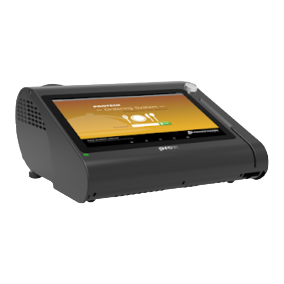
Summary of Contents for protech PA-3211
- Page 1 USER MANUAL PA-3211 10.1” POS Terminal Powered by ARM Cortex A-9 Processor PA-3211 M1...
- Page 2 PA-3211 POS System Powered by ARM Cortex-A9 Processor COPYRIGHT NOTICE & TRADEMARK All trademarks and registered trademarks mentioned herein are the property of their respective owners. This manual is copyrighted in October 2017. You may not reproduce or transmit in any form or by any means, electronic, or mechanical, including photocopying and recording.
- Page 3 FCC NOTICE This equipment has been tested and found to comply with the limits for a Class A digital device, pursuant to part 15 of the FCC Rules. These limits are designed to provide reasonable protection against harmful interference when the equipment is operated in a commercial environment.
-
Page 4: Table Of Contents
Contents Revision History ..................... vi Introduction ..................1-1 About This Manual ..............1-2 Getting Started ..................2-1 Package List ................2-2 System Views Without i-Button Module ........2-3 2.2.1 Front View ................. 2-3 2.2.2 Rear View ................2-3 2.2.3 Top View ................2-4 2.2.4 Bottom View .............. - Page 5 Jumper & Connector Quick Reference Table ......3-3 Component Locations Of System Main Board ......3-5 3.3.1 Top View of System Main Board ........3-5 How To Set Jumpers ..............3-7 Function Buttons and Rear I/O Ports ........3-9 3.5.1 Power Button ..............
- Page 6 3.6.13 HD Audio Connector ............3-23 3.6.14 I2C Connector ..............3-24 3.6.15 Inverter Backlight Enable Selection ......... 3-25 3.6.16 Touch Panel Signal Interface Selection ......3-25 3.6.17 Mini PCIE USB Selection ..........3-26 3.6.18 LVDS Panel Input Voltage Selection ....... 3-26 3.6.19 LVDS Voltage Selection ...........
- Page 7 3.8.3.1 Power Switch Selection ..........3-43 3.8.3.2 RS-232 Serial Interface Connector ......3-44 MSR Board Component Locations & Pin Assignment .... 3-45 3.9.1 MB-3013 ................3-45 3.9.1.1 Information Button Reader ........... 3-45 3.9.1.2 Output Connector ............3-45 Software Utilities ................. 4-1 Peripheral Devices ..............
- Page 8 Appendix A System Diagrams ............ A-1 Exploded Diagram For System Top Case ..........A-2 System Exploded Diagram ...............A-3 Exploded Diagram For MSR Module ............A-9 Exploded Diagram For 3-Inch Printer (1) ..........A-10 Exploded Diagram For 3-Inch Printer (2) ..........A-12 Exploded Diagram For 2-Inch Printer (1) ..........A-13 Exploded Diagram For 2-Inch Printer (2) ..........A-15 Exploded Diagram For VFD Module ............A-16...
-
Page 9: Revision History
Revision History The revision history of PA-3211 User Manual is described below: Version No. Revision History Page No. Date Initial Release 2017/10/05... -
Page 10: Introduction
Introduction This chapter provides the introduction for the PA-3211 system as well as the framework of the user manual. The following topic is included: • About This Manual PA-3211 SERIES USER MANUAL Page: 1-1... -
Page 11: About This Manual
Chapter 1 Introduction 1.1 About This Manual Thank you for purchasing our PA-3211 system. The PA-3211 is an updated system designed to be comparable with the highest performance of IBM AT personal computers. The PA-3211 provides faster processing speed, greater expandability and can handle more tasks than before. -
Page 12: Getting Started
Getting Started This chapter provides the information for the PA-3211 system. It describes how to set up the system quickly and outlines the system specifications. The following topics are included: • Package List • System Overview • System Diagrams • System Specification •... -
Page 13: Package List
Item Q’ty PA-3211 Manual / Driver DVD Quick Reference Guide AC Power Cord (Optional) MSR Card Reader (Optional) i-Button + MSR Card Reader (Optional) Wireless LAN (IEEE 802.11 b/g/n) (Optional) VFD (Optional) PA-3211 SERIES USER MANUAL Page: 2-2... -
Page 14: System Views Without I-Button Module
Chapter 2 Getting Started 2.2 System Views Without i-Button Module 2.2.1 Front View Unit: mm 2.2.2 Rear View PA-3211 SERIES USER MANUAL Page: 2-3... -
Page 15: Top View
Chapter 2 Getting Started 2.2.3 Top View PA-3211 SERIES USER MANUAL Page: 2-4... -
Page 16: Bottom View
Chapter 2 Getting Started 2.2.4 Bottom View 2.2.5 Quarter View PA-3211 SERIES USER MANUAL Page: 2-5... -
Page 17: Side View
Chapter 2 Getting Started 2.2.6 Side View Unit: mm PA-3211 SERIES USER MANUAL Page: 2-6... -
Page 18: System Views With I-Button Module
Chapter 2 Getting Started 2.3 System Views With i-Button Module 2.3.1 Front View 2.3.2 Rear View PA-3211 SERIES USER MANUAL Page: 2-7... -
Page 19: Top View
Chapter 2 Getting Started Top View 2.3.3 PA-3211 SERIES USER MANUAL Page: 2-8... -
Page 20: Bottom View
Chapter 2 Getting Started 2.3.4 Bottom View 2.3.5 Quarter View PA-3211 SERIES USER MANUAL Page: 2-9... -
Page 21: Side View
Chapter 2 Getting Started 2.3.6 Side View PA-3211 SERIES USER MANUAL Page: 2-10... -
Page 22: System Specifications
ISO I/II/III , JIS I/II/UART interface Display 10.1" TFT LCD 1280 x 800 Resolution 400 cd/m² Brightness 10.1" Capacitive Touch panel Touch Screen 24 ~ 30 degree Tilt Angle PA-3211 SERIES USER MANUAL Page: 2-11... - Page 23 Chapter 2 Getting Started Environment CE / FCC EMC & Safety 0°C ~ 35°C (32°F ~ 95°F) Operating Temp. -20°C ~ 60°C (-4°F ~ 140°F) Storage Temp. 20% ~ 90% Humidity PA-3211 SERIES USER MANUAL Page: 2-12...
-
Page 24: Safety Precautions
Avoid direct sunlight exposure for a long period of time (for example, in a closed car in summer time. Also avoid the system from any heating device.). Or do not use PA-3211 when it has been left outdoors in a cold winter day. •... -
Page 25: System Configuration
• Setting Main Board Connectors and Jumpers • Printer Board Component Locations & Pin Assignment • Setting Printer Board Connectors and Jumpers MB-1030 series • Setting VFD Board Connectors and Jumpers • Setting MSR PA-3211 SERIES USER MANUAL Page: 3-1... -
Page 26: External System I/O Ports Diagram & Pin Assignment
Chapter 3 Hardware Configuration 3.1 External System I/O Ports Diagram & Pin Assignment 3.1.1 Rear I/O Ports Diagram USB (option) DRW2 (option) UART (option) UART UPDATE DC IN MicroSD USB1 DRW1 extended with Y cable DRW1-1 DRW1-2 PA-3211 SERIES USER MANUAL Page: 3-2... -
Page 27: Jumper & Connector Quick Reference Table
External USB 2.0 Port (side bezel) USB2 USB0, USB1_2, USB2_2, USB3, Internal USB 2.0 Connectors USB4_2, USB5 UART0, UART1, UART2, Internal UART Connectors UART3_1, UART5 Power for Thermal Printer Connector OUT_24V DC12V, DC 5V Power Connectors OUT_12V, OUT_5V PA-3211 SERIES USER MANUAL Page: 3-3... - Page 28 Chapter 3 Hardware Configuration System CONNECTOR Description NAME Power LED Connectors LED1_1, LED1_2 LVDS Connector LVDS1 Mini PCIE Connector M_PCIE Power Switch Connector Inverter Connector INV1 External Speaker Connector SPK1 HD Audio Connector LINE_OUT1 I2C Connector PA-3211 SERIES USER MANUAL Page: 3-4...
-
Page 29: Component Locations Of System Main Board
Make sure both the system and peripheral devices are turned OFF as sudden surge of power could damage sensitive components. Make sure PA-3211 is properly grounded. CAUTION: Observe precautions while handling electrostatic sensitive components. Make sure to ground yourself to prevent static charge while you are working on the connectors and jumpers. - Page 30 CAUTION: Always touch the motherboard components by the edges. Never touch components such as a processor by its pins. Take special cares while you are holding electronic circuit boards by the edges only. Do not touch the mainboard components. PA-3211 SERIES USER MANUAL Page: 3-6...
-
Page 31: How To Set Jumpers
2 to create one setting and shorting. You can also select to connect pins 2 and 3 to create another setting. The format of the jumper picture will be illustrated throughout this manual. The figure below shows different types of jumpers and jumper settings. PA-3211 SERIES USER MANUAL Page: 3-7... - Page 32 Chapter 3 Hardware Configuration Jumper diagrams Jumper settings PA-3211 SERIES USER MANUAL Page: 3-8...
-
Page 33: Function Buttons And Rear I/O Ports
Description: DC Power-In Port (rear I/O) PIN ASSIGNMENT PIN ASSIGNMENT 24VIN +24V DC_IN1 3.5.3 Cash Drawer Port Port Name: DRW1 Description: DRW1 is used by default (rear I/O). ASSIGNMENT Drwaer2_Open Drawer Open Drawer Sense 12V/24V DRW1 Drawer2_Sensor_R PA-3211 SERIES USER MANUAL Page: 3-9... -
Page 34: Uart3 Connector
Note: UART3 and UART3_1 can't be used at the same time. 3.5.5 VGA Port Port Name: VGA1 Description: VGA Port, D-Sub 15-pin (rear I/O) PIN ASSIGNMENT PIN ASSIGNMENT VGA1 GREEN BLUE DDCA DATA HSYNC VSYNC DDCA CLK PA-3211 SERIES USER MANUAL Page: 3-10... -
Page 35: Usb Port
Chapter 3 Hardware Configuration 3.5.6 USB Port Port Name: USB1 Description: USB Type A Port (rear I/O) ASSIGNMENT +5V (Max. current: 0.5A) USB1 PA-3211 SERIES USER MANUAL Page: 3-11... -
Page 36: Lan Port
There is a LAN LED indicator for LAN on the rear panel of the system. By observing its status, you can know the status of the Ethernet connection. LAN LED Color Status Description Indicator Right Side 10/100Mbps LAN Speed Indicator Green No LAN switch/ hub connected. PA-3211 SERIES USER MANUAL Page: 3-12... -
Page 37: Microsd Port
ASSIGNMENT SD0_D2 MICRO_SD1 SD0_D3 SD0_CMD SD_VCC SD0_CLK SD0_D0 SD0_D1 CARD_DET 3.5.9 Micro USB Port Port Name: UPDATE Description: Image Update Port (rear I/O) ASSIGNMENT UPDATE DET: high -> ADFU DET: low -> USB HUB PA-3211 SERIES USER MANUAL Page: 3-13... -
Page 38: Setting Main Board Connectors And Jumpers
UART0, UART1, UART2, UART3, UART5 ports can be adjusted by setting relevant jumpers on board. JUMPER SELECTION JUMPER ILLUSTRATION SETTING (Default Setting) JP_COM1 JP_COM0 JP_COM3 JP_COM2 JP_COM5 +12V JP_COM1 JP_COM0 JP_COM3 JP_COM2 JP_COM5 JP_COM0 JP_COM1 JP_COM2 JP_COM3 JP_COM5 PA-3211 SERIES USER MANUAL Page: 3-14... -
Page 39: External Usb 2.0 Port
Chapter 3 Hardware Configuration 3.6.2 External USB 2.0 Port Connector Location: USB2 Description: USB Type A Connector (on side bezel) ASSIGNMENT +5V (Max. current: 0.5A) USB2 PA-3211 SERIES USER MANUAL Page: 3-15... -
Page 40: Internal Usb 2.0 Connectors
USB4_2 signal is shared from "MINI_PCIE" port. USB4_2 could be functioned when JP9, JP10 are set as 1-2 (short) connected. USB5 could be functioned when JP5, JP6 are set as 1-2 (short) connected. USB0/ USB2_2/ USB3/ USB5 PA-3211 SERIES USER MANUAL Page: 3-16... -
Page 41: Internal Uart Connectors
UART0/ UART1 UART2/ UART5 Connector Location: UART3_1 Description: UART Connector ASSIGNMENT ASSIGNMENT COM1_RXD_R COM1_RTS_R COM1_TXD_R COM1_CTS_R RI / +5V / +12V selectable UART3_1 Note: UART3 and UART3_1 can't be used at the same time. PA-3211 SERIES USER MANUAL Page: 3-17... -
Page 42: Power For Thermal Printer Connector
24VIN 24VIN OUT_24V 3.6.6 Power Connectors (DC 12V, DC 5V) Connector Location: OUT_12V Description: DC 12V Voltage Provider Connector ASSIGNMENT VCC12 OUT_12V Connector Location: OUT_5V Description: DC 5V Voltage Provider Connector ASSIGNMENT V5P0A OUT_5V PA-3211 SERIES USER MANUAL Page: 3-18... -
Page 43: Power Led Connectors
Chapter 3 Hardware Configuration 3.6.7 Power LED Connectors Connector Location: LED1_1, LED1_2 Description: Power indication LED Connector ASSIGNMENT LED1_1 VCC5 LED1_2 PA-3211 SERIES USER MANUAL Page: 3-19... -
Page 44: Lvds Connector
Description: LVDS Connector ASSIGNMENT ASSIGNMENT LVDS_VCC LVDS_VCC Panel_reverse1 LVDS_VCC GPIOD16/PWM5 LVDS_VCC LVDS1 VLED VLED VLED VLED LVDS_A3_DP LVDS_A3_DN LVDS_CLKA_DP LVDS_CLKA_DN LVDS_A2_DP LVDS_A2_DN LVDS_A1_DP LVDS_A1_DN LVDS_A0_DP LVDS_A0_DN LVDS_B3_DP LVDS_B3_DN LVDS_CLKB_DP LVDS_CLKB_DN LVDS_B2_DP LVDS_B2_DN LVDS_B1_DP LVDS_B1_DN LVDS_B0_DP LVDS_B0_DN PA-3211 SERIES USER MANUAL Page: 3-20... -
Page 45: Mini Pcie Connector
Chapter 3 Hardware Configuration 3.6.9 Mini PCIE Connector Connector Location: M_PCIE Description: Mini PCIE Connector ASSIGNMENT ASSIGNMENT GPIOD12/ V3P3A M_PCIE WL_WAKE V1P5S V3P3A V3P3A GPIOB2/WL_EN V3P3A V1P5S USB_N USB_P V3P3A V3P3A V1P5S V3P3A PA-3211 SERIES USER MANUAL Page: 3-21... -
Page 46: Power Switch Connector 2
Power Switch Connector 2 Connector Location: SW2 Description: Power Switch Connector 2 ASSIGNMENT CONOFF 3.6.11 Inverter Connector Connector Location: INV1 Description: Inverter Connector ASSIGNMENT INV1 VCC12/VCC5 by JP16 VCC12/VCC5 by JP16 BRCTR_INV(Brightness) PANLE_BKLTEN_C (Enable) 5V/3.3V by JP4 PA-3211 SERIES USER MANUAL Page: 3-22... -
Page 47: External Speaker Connector
Chapter 3 Hardware Configuration 3.6.12 External Speaker Connector Connector Location: SPK1 Description: External Speaker Connector ASSIGNMENT SPK1 HD_FRONT-OUT1-R HD_FRONT-OUT1-L 3.6.13 HD Audio Connector Connector Location: LINE_OUT1 Description: HD Audio Connector ASSIGNMENT AOUTL LINE_OUT1 AOUTR PA-3211 SERIES USER MANUAL Page: 3-23... -
Page 48: I2C Connector
Chapter 3 Hardware Configuration 3.6.14 I2C Connector Connector Location: I2C Description: I2C Connector ASSIGNMENT VCC3_3_LDO I2CSCL I2CSDA INT_18 RSTN_3 PA-3211 SERIES USER MANUAL Page: 3-24... -
Page 49: Inverter Backlight Enable Selection
SELECTION JUMPER SETTING JUMPER ILLUSTRATION 3.3V (Default Setting) 3.6.16 Touch Panel Signal Interface Selection Jumper Name: JP5, JP6 Description: Touch Panel Signal Interface Selection SELECTION JUMPER SETTING JUMPER ILLUSTRATION USB5 JP5/JP6 Connector (Default Setting) PA-3211 SERIES USER MANUAL Page: 3-25... -
Page 50: Mini Pcie Usb Selection
USB signal to JP9/JP10 mini-PCIE (Default Setting) 3.6.18 LVDS Panel Input Voltage Selection Jumper Name: JP14 Description: LVDS Panel Input Voltage Selection SELECTION JUMPER SETTING JUMPER ILLUSTRATION Enable (Default Setting) JP14 SW Enable JP14 PA-3211 SERIES USER MANUAL Page: 3-26... -
Page 51: Lvds Voltage Selection
Description: LVDS 3.3V / 5V / 12V Voltage Selection JUMPER SELECTION JUMPER ILLUSTRATION SETTING 1-3, 2-4 (JP15) 3.3V 1-3, 2-4 (JP17) (Default Setting) JP17 JP15 3-5, 4-6 (JP15) 1-3, 2-4 (JP17) JP17 JP15 +12V 3-5, 4-6 (JP17) JP17 PA-3211 SERIES USER MANUAL Page: 3-27... -
Page 52: Inverter Voltage Selection
Chapter 3 Hardware Configuration 3.6.20 Inverter Voltage Selection Jumper Name: JP16 Description: Inverter Voltage Selection SELECTION JUMPER SETTING JUMPER ILLUSTRATION 1-3, (Default Setting) JP16 3-5, JP16 PA-3211 SERIES USER MANUAL Page: 3-28... -
Page 53: Image Detection Selection
Chapter 3 Hardware Configuration 3.6.21 Image Detection Selection Jumper Name: JP18 Description: Image Detection Selection SELECTION JUMPER SETTING JUMPER ILLUSTRATION ADFU Mode JP18 USB HUB Function (Default Setting) JP18 Note: ADFU stands for actions device firmware upgrade. PA-3211 SERIES USER MANUAL Page: 3-29... -
Page 54: Usb1_2 Or Usb1 Selection
3-5, USB1 (Default Setting) JP_USB1 3.6.23 USB2 or USB2_2 Selection Jumper Name: JP_USB2 Description: USB2 or USB2_2 Connector Selection SELECTION JUMPER SETTING JUMPER ILLUSTRATION 1-3, USB2 Connector (Default Setting) JP_USB2 USB2_2 3-5, Connector JP_USB2 PA-3211 SERIES USER MANUAL Page: 3-30... -
Page 55: Cash Drawer Control Selection (Jp8)
DRW1-1 & DRW1-2 with a Y-cable. DRW1, DRW1-1, DRW1-2 shares the same power source (refer to the Cash Drawer Power Selection section for adjustment, default: 12V). DRW1-1 (Connect with Y-cable) DRW1 GPIO2 DRW1-1 JP37 DRW1 DRW1-2 GPIO1 DRW1-2 PA-3211 SERIES USER MANUAL Page: 3-31... -
Page 56: Cash Drawer Control Selection
Chapter 3 Hardware Configuration 3.6.25 Cash Drawer Control Selection Jumper Name: JP8 Description: Cash Drawer Control Selection SELECTION JUMPER SETTING JUMPER ILLUSTRATION Drawer2 Drawer1 (Default Setting) PA-3211 SERIES USER MANUAL Page: 3-32... -
Page 57: Cash Drawer Power Selection
Chapter 3 Hardware Configuration 3.6.26 Cash Drawer Power Selection Jumper Name: JP7 Description: DRW1, DRW1-1, DRW1-2 Power Selection SELECTION JUMPER SETTING JUMPER ILLUSTRATION (Default Setting) PA-3211 SERIES USER MANUAL Page: 3-33... -
Page 58: Printer Board Component Locations & Pin Assignment
Chapter 3 Hardware Configuration 3.7 Printer Board Component Locations & Pin Assignment 3.7.1 Printer Board: MB-1030 series CUT_CN1 COM1 9 10 USB_CN1 24V_CN1 PRINT_CN1 Figure 3-2. MB-1030 Printer Board Component Locations PA-3211 SERIES USER MANUAL Page: 3-34... -
Page 59: Jumper & Connector Quick Reference Table
Jumper & Connector Quick Reference Table Jumper / Connector NAME Power Supply Connector 24V_CN1 RS-232 Interface Connector COM1 Thermal Head/Motor/Sensor Connector PRINT_CN1 Auto-Cutter Connector CUT_CN1 Paper-Near-END Sensor Connector USB Interface Connector USB_CN1 Terminal Assignment Connector PA-3211 SERIES USER MANUAL Page: 3-35... - Page 60 Setting Printer Board Connectors and Jumpers 3.7.2.1 Power Supply Connector 24V_CN1: Power Supply Wafer ASSIGNMENT +24V +24V 24V_CN1 3.7.2.2 RS-232 Interface Connector COM1: RS-232 Interface Connector ASSIGNMENT ASSIGNMENT DSR /CTS DTR /RTS 9 10 COM1 PA-3211 SERIES USER MANUAL Page: 3-36...
- Page 61 Head strobe signal DST1 Head strobe signal Head GND Head GND Head GND Head GND Head GND Head GND LATCH Print data latch Head drive power Head drive power Head drive power Head drive power PA-3211 SERIES USER MANUAL Page: 3-37...
- Page 62 Power supply of the out-of-paper sensor GND of the platen position/ out-of-paper sensor Signal of the platen position sensor Unused Frame GND Frame GND Unused Motor drive signal Motor drive signal Motor drive signal Motor drive signal PA-3211 SERIES USER MANUAL Page: 3-38...
- Page 63 1A-2 Auto-cutter motor drive signal 3.7.2.5 Paper-Near-END Sensor Connector CN2: Paper-near-end sensor connector ASSIGNMENT FUNCTION Power supply of the near end sensor Signal of the near end sensor GND of the near end sensor PA-3211 SERIES USER MANUAL Page: 3-39...
- Page 64 Feed signal RESET Reset signal Status signal Status signal Status signal Status signal Drawer sensor signal Drawer switch signal Drive terminal for the drawer (Vp side) GNDdu Drive terminal for the drawer (GND side) Unused PA-3211 SERIES USER MANUAL Page: 3-40...
-
Page 65: Vfd Board Component Locations & Pin Assignment
Chapter 3 Hardware Configuration 3.8 VFD Board Component Locations & Pin Assignment 3.8.1 VFD Board: MB-4103 JP12V Figure 3-3. MB-4103 VFD Board Component Locations PA-3211 SERIES USER MANUAL Page: 3-41... -
Page 66: Jumper & Connector Quick Reference Table
Chapter 3 Hardware Configuration 3.8.2 Jumper & Connector Quick Reference Table Jumper / Connector NAME Power Switch Selection JP12V RS-232 Serial Interface Connector PA-3211 SERIES USER MANUAL Page: 3-42... -
Page 67: Setting Mb-4103 Vfd Board Connectors And Jumpers
Chapter 3 Hardware Configuration 3.8.3 Setting MB-4103 VFD Board Connectors and Jumpers 3.8.3.1 Power Switch Selection JP12V: Power Switch Selection SELECTION JUMPER SETTING JUMPER ILLUSTRATION JP12V (Default Setting) JP12V PA-3211 SERIES USER MANUAL Page: 3-43... -
Page 68: Serial Interface Connector
Chapter 3 Hardware Configuration 3.8.3.2 RS-232 Serial Interface Connector CN1: RS-232 serial interface wafer ASSIGNMENT ASSIGNMENT +12V/+5V PA-3211 SERIES USER MANUAL Page: 3-44... -
Page 69: Msr Board Component Locations & Pin Assignment
MB-3013 MSR Board Component Locations 3.9.1.1 Information Button Reader I_BUTTON1: Information button reader ASSIGNMENT I_B1 I_BUTTON1 3.9.1.2 Output Connector IO1: Output wafer ASSIGNMENT ASSIGNMENT CLK_KB RX_MSR CLK_PC TX_MSR DATA_KB DATA_PC USB_D+_R USB_D-_R CHASSIS GND PA-3211 SERIES USER MANUAL Page: 3-45... -
Page 70: Software Utilities
VFD, API and instructs how to burn the image onto PB-3211 board. The following topics are included: • Peripheral Devices - Printer Board (MB-1030) Commands - VFD (MB-4103) Commands • API • Burning the Image onto PB-3211 Board PA-3211 SERIES USER MANUAL Page: 4-1... -
Page 71: Peripheral Devices
GS h FS q GS k ESC 2 GS ! GS r ESC 3 GS $ GS v 0 ESC = GS * GS w ESC ? GS ( A ESC @ GS ( K Page: 4-2 PA-3211 SERIES USER MANUAL... -
Page 72: Commands List
Print data in page mode Ignored <ESC SP> 1B 20 Set right-side character spacing <ESC !> 1B 21 Select print mode(s) <ESC $> 1B 24 Set absolute print position. <ESC *> 1B 2A Select bit image mode PA-3211 SERIES USER MANUAL Page: 4-3... - Page 73 1D 2A Define download bit images <GS ( A> 1D 28 41 Execute test print Disabled <GS ( K> 1D 28 4B Set print density Disabled ● <GS /> 1D 2F Print download bit image Page: 4-4 PA-3211 SERIES USER MANUAL...
- Page 74 ● <GS k> 1D 6B Print bar code <GS r> 1D 72 Transmit status ● <GS v 0> 1D 76 30 Print raster bit image Disabled <GS w> 1D 77 Set bar code width PA-3211 SERIES USER MANUAL Page: 4-5...
- Page 75 ●: Enabled only when data is not present in the printer buffer. ▲: Only value setting is possible. Disabled: Parameters are processed as printable data. Ignored: All command codes including parameters are ignored and nothing is executed. Page: 4-6 PA-3211 SERIES USER MANUAL...
- Page 76 After execution, makes the top of the line the next print starting position. [Name] Print and recover to standard mode (in page mode) ASCII [Format] Hex. Decimal 12 [Range] Prints all buffered data to the print region collectively, then recovers to the standard [Description] mode. PA-3211 SERIES USER MANUAL Page: 4-7...
- Page 77 Deletes all print data in the currently set print region in page mode. This command is enabled only in page mode. [Description] Portions included in the currently set print region are also deleted, even if previously set print region data. Page: 4-8 PA-3211 SERIES USER MANUAL...
- Page 78 No error. Error occurs. Not used. Fixed to Off. n = 3 : Error status On / Off Decimal Function Not used. Fixed to Off. Not used. Fixed to On. Not used. Fixed to Off. PA-3211 SERIES USER MANUAL Page: 4-9...
- Page 79 = 1: Recover from the error and start printing from the line where the error [Description] occurred. n = 2: Recover from error after clearing the reception buffer and print buffer. This command is enabled even when the printer specification is disabled by ESC = (select peripheral devices). Page: 4-10 PA-3211 SERIES USER MANUAL...
- Page 80 [Format] Hex. Decimal 0 ≤ n ≤ 255 [Range] Initial Value n = 0 This command sets the size of space to right of character. [Description] Right space = n × [horizontal motion units]. PA-3211 SERIES USER MANUAL Page: 4-11...
- Page 81 This command specifies the next print starting position in reference to the left edge of the print area. The printing start position is calculated using (nL + nH x [Description] 256) x (vertical or horizontal motion units). Specifications exceeding the print range are ignored. Page: 4-12 PA-3211 SERIES USER MANUAL...
- Page 82 67 DPI 101 DPI nL+nH×256 density 8 dot double 67 DPI 203 DPI nL+nH×256 density 24 dot (nL+nH×256) single 203 DPI 101 DPI ×3 density 24 dot (nL+nH×256) double 203 DPI 203 DPI ×3 density PA-3211 SERIES USER MANUAL Page: 4-13...
- Page 83 Hex. Decimal 0 ≤ n ≤ 255 [Range] Initial Value n = 34 This command sets the line spacing using a following rule. [Description] Line spacing = n x (vertical or horizontal motion units) Page: 4-14 PA-3211 SERIES USER MANUAL...
- Page 84 n specifies the column number for setting a horizontal tab position from the [Description] left margin or the beginning of the line. k indicates the number of horizontal tab positions to be set. PA-3211 SERIES USER MANUAL Page: 4-15...
- Page 85 In page mode, this command functions as follows, depending on the starting position of the printable area: (1) When the starting position is set to the upper left or lower right of the printable area using ESC T, the vertical motion unit (y) is used. Page: 4-16 PA-3211 SERIES USER MANUAL...
- Page 86 FS q : Define NV bit image c. GS v 0 : Print raster bit images d. GS L : Set left margin Recover to standard mode using ESC @ (initialize printer). PA-3211 SERIES USER MANUAL Page: 4-17...
- Page 87 Initial Value n = 0 [Description] This command specifies international characters according to n values. Character Set France Germany Denmark I Sweden Italy Spain Japan Norway Denmark II Spain II Latin America Korea Russia Slavonic Page: 4-18 PA-3211 SERIES USER MANUAL...
- Page 88 GS $ :Specify absolute position for character vertical direction in page Mode GS \: :Specify relative position for character vertical direction in page mode Standard mode is selected when the power is turned on, the printer is reset or initialized (ESC @). PA-3211 SERIES USER MANUAL Page: 4-19...
- Page 89 Underlines are not applied to characters rotated 90 degrees clockwise even when ESC !,ESC - or FS - commands are given. If 90 degree clockwise rotation is specified, double-wide and double-tall commands in the 90 rotation mode enlarges characters in the opposite Page: 4-20 PA-3211 SERIES USER MANUAL...
- Page 90 - horizontal starting position). If (vertical starting position + printing area height) exceeds the printable area, the printing area height is automatically set to (vertical printable area [Description] - vertical starting position). PA-3211 SERIES USER MANUAL Page: 4-21...
- Page 91 This command specifies position alignment for all data in one line in standard mode, using n as follows: Alignment Left alignment [Description] Center alignment Right alignment This command has no effect in page mode. Page: 4-22 PA-3211 SERIES USER MANUAL...
- Page 92 Selects the paper out detector to stop printing when paper has run out. “0” “1” Function Undefined Undefined Undefined [Description] Undefined Undefined Undefined Paper roll near end detector Invalid Valid Paper roll near end detector Invalid Valid PA-3211 SERIES USER MANUAL Page: 4-23...
- Page 93 This command executes a full cut of the paper in standard mode ESC m [Name] Partial cut. ASCII [Format] Hex. Decimal [Range] This command executes a partial cut of the paper with one point uncut in [Description] standard mode. Page: 4-24 PA-3211 SERIES USER MANUAL...
- Page 94 Hex. Decimal 0 ≤ n ≤ 8 [Range] Initial Value n = 0 Select page n of the character code table. Character set CP-437 Katakana CP-850 CP-852 [Description] CP-860 CP-863 CP-865 CP-1252 User Define PA-3211 SERIES USER MANUAL Page: 4-25...
- Page 95 NV bit image is a bit image defined in non-volatile memory by FS q and printed by this command. This command is ignored when the specified NV bit image n is undefined. Page: 4-26 PA-3211 SERIES USER MANUAL...
- Page 96 xL and xH specify the horizontal direction for one NV bit image (xL + xH x 256) x 8 dots. yL and yH specify the vertical direction for one NV bit image (yL + yH x 256) x 8 dots. PA-3211 SERIES USER MANUAL Page: 4-27...
- Page 97 4 times 5 times 6 times 7 times 8 times Table 2 [Enlarged in vertical direction] Decimal Enlargement 1 time(standard) 2 times 3 times 4 times 5 times 6 times 7 times 8 times Page: 4-28 PA-3211 SERIES USER MANUAL...
- Page 98 [(nL + nH x 256) x basic [Description] calculated pitch] from the starting point. When not in page mode, this command is ignored. Specifications for absolute positions that exceed the specified print range are ignored. PA-3211 SERIES USER MANUAL Page: 4-29...
- Page 99 Horizontal direction dot count is X x 8 dots; Vertical direction dot count is Y x 8 dots d indicates the bit-image data. Bits that correspond to the dots to print are 1, and the bits that correspond to the dots that are not printed are 0. [Description] Page: 4-30 PA-3211 SERIES USER MANUAL...
- Page 100 Basic sheet (paper roll) [Description] 1 , 49 Paper Roll 2 , 50 m specifies a test pattern. Type of Test Print 2 , 50 Printer Status (Self Print) 3 , 51 Rolling Pattern Print PA-3211 SERIES USER MANUAL Page: 4-31...
- Page 101 This command prints the downloaded bit image defined by GS * according to the mode denoted by m. Vertical dot Horizontal dot Mode [Description] density(DPI) density(DPI) 0 , 48 Normal 1 , 49 Double-width 2 , 50 Double-height 3 , 51 Quadruple Page: 4-32 PA-3211 SERIES USER MANUAL...
- Page 102 Selects the printing position of HRI characters when printing bar codes. Printing Position 0, 48 No print [Description] 1, 49 Above bar code 2, 50 Below bar code 3, 51 Above and below bar code(both) PA-3211 SERIES USER MANUAL Page: 4-33...
- Page 103 0 ≤ nL ≤ 255, 0 ≤ nH ≤ 255 [Range] Initial Value (nL + nH x 256)=0 (nL=0, nH=0) nL and nH set the specified left margin. The left margin is [(nL + nH x 256) x basic calculated pitch]. [Description] Page: 4-34 PA-3211 SERIES USER MANUAL...
- Page 104 Feeds paper to (cutting position + [n x basic calculated pitch]) and performs a full cut Feeds paper to (cutting position + [n x basic calculated pitch]) and performs a partial cut (one point uncut) PA-3211 SERIES USER MANUAL Page: 4-35...
- Page 105 [(nL + nH x 256) x basic calculated pitch] for the next data expanding starting position. When not in page mode, this command is ignored. Page: 4-36 PA-3211 SERIES USER MANUAL...
- Page 106 Cover is open Not used. Fixed to On On-line Off-line Drawer kick-out connector pin 3 is LOW Drawer kick-out connector pin 3 is HIGH Not used. Fixed to Off Not used. Fixed to Off PA-3211 SERIES USER MANUAL Page: 4-37...
- Page 107 Black mark sensor status Not used. Fixed to Off Not used. Fixed to Off Not used. Fixed to On Not used. Fixed to On Not used. Fixed to On Not used. Fixed to On Page: 4-38 PA-3211 SERIES USER MANUAL...
- Page 108 Selects Font B (9 x 17). GS h n [Name] Set bar code height. [Format] ASCII Hex. Decimal 104 n 1 ≤ n ≤ 255 [Range] Initial Value n = 162 [Description] Sets bar code height to n dots. PA-3211 SERIES USER MANUAL Page: 4-39...
- Page 109 48 ≤ d ≤ 57, 65 ≤ d ≤ 68, CODABAR 36, 43, 45, 46, 47, 58 1 ≤ n ≤ 255 0 ≤ d ≤ 127 CODE93 2 ≤ n ≤ 255 0 ≤ d ≤ 127 CODE128 Page: 4-40 PA-3211 SERIES USER MANUAL...
- Page 110 Paper roll near end detector Has Paper Paper out [Description] Drawer Kick Connector Status (n=2,50) “0” “1” Status Fixed at 0 Undefined Undefined Fixed at 0 Undefined Undefined Undefined “L” “H” Drawer kick connector pin PA-3211 SERIES USER MANUAL Page: 4-41...
- Page 111 xL and xH specify the horizontal direction data count for one bit image (xL + xH x 256) in bytes. yL and yH specify the vertical direction data count for one bit image (yL + yH x 256) in bytes. [Description] Page: 4-42 PA-3211 SERIES USER MANUAL...
- Page 112 2 ≤ n ≤ 16 [Range] Initial Value n = 2 Specifies a module size of QR Code and Data Matrix. [Description] n: The number of dots for one side of the module size. PA-3211 SERIES USER MANUAL Page: 4-43...
- Page 113 Mode Numerical mode Alphanumeric mode 8-bit byte mode Kanji mode Mixed mode nl, nh: Specifies the number of data. Data: Kanji data of the QR Code data should be set by Shift JIS code. Page: 4-44 PA-3211 SERIES USER MANUAL...
- Page 114 Batch specifies the Kanji character print mode. “0” “1” Function Underline Undefined Undefined Undefined Double tall expanded Expanded wide Undefined Undefined FS & [Name] Select Kanji character mode. ASCII & [Format] Hex. Decimal [Range] [Description] Specifies Kanji character mode. PA-3211 SERIES USER MANUAL Page: 4-45...
- Page 115 Kanji character underlines. 2,50 Sets to two-dot width Kanji character underline and cancels Kanji character underlines. FS . [Name] Cancel Kanji character mode. ASCII [Format] Hex. Decimal [Range] [Description] Cancels Kanji character mode. Page: 4-46 PA-3211 SERIES USER MANUAL...
- Page 116 Specifies or cancels quadruple size Kanji character. Cancels quadruple size when n = <*******0>B. [Description] Specifies quadruple size when n = <*******1>B. n is effective only when it is the lowest bit. PA-3211 SERIES USER MANUAL Page: 4-47...
-
Page 117: Vfd: Mb-4103 (Rs-232)
0≦n ≦5 ( Please refer Chapter 5 ) ESC R n 1B 52 n Select international character set ( Please refer to International Font Set Table ) US r n 1F 72 n Select/cancel reverse character Page: 4-48 PA-3211 SERIES USER MANUAL... - Page 118 1≦x1≦x2≦20 (column) ; 1≦y1≦y2≦2 (row) US @ 1F 40 Execute self-test Display time : 0≦h ≦23; 0≦m≦ 59 US T h m 1F 54 h m US U 1F 55 Display of time counter PA-3211 SERIES USER MANUAL Page: 4-49...
-
Page 119: Api Package Content
Chapter 4 Software Utilities 4.2 API 4.2.1 API Package Content You can find the enclosed API Package files in the Protech Manual /Driver DVD. Depending on the machine types, the API Package may include the following files: Android Framework Operation System... -
Page 120: Programming Guide
JAR file into build path using [Add Jars...]. 4. Copy the library file (libeposprint.so) into following path: Libs -x86 |_ libgpio_control.so |_libserial_port.so Import Function Declare: importandroid.VFD.VFD; importandroid.VFD.Msr; importandroid.CashDrawer.CashDrawer; importandroid.ThermalPrinter.ThermalPrinter; PA-3211 SERIES USER MANUAL Page: 4-51... -
Page 121: Api Reference
Value back. Return True (1) on success, False (0) on failure False (0) booleanControlResult = false; Example CashDrawerCDrawer =newCashDrawer(); ControlResult = CDrawer.GetCashDrawerStatus(1); if(ControlResult) //"Cash Drawer Status Open !" else //"Cash Drawer Status Close !" Page: 4-52 PA-3211 SERIES USER MANUAL... -
Page 122: Vfd Api
True (1) on success, False (0) on failure False (0) Example VFD – Clear VFD Command (EPSON Command) //Initialize a VFD class instance VFD_Control VFD(); VFD_Control.OpenVFD(9600); byte[] data = newbyte[1]; data[0] = 0x0C; VFD_Control.SendCommand(data); VFD_Control.CloseVFD(); PA-3211 SERIES USER MANUAL Page: 4-53... -
Page 123: Msr Api
True (1) on success, False (0) on failure False (0) Msr – Send Command to Msr Example //Initialize a VFD class instance MsrMsrcontrol = newMsr(); Msrcontrol.OpenMSR(19200); byte[] data = newbyte[1]; data[0] = 0x0C; Msrcontrol.SendCommand(data); Page: 4-54 PA-3211 SERIES USER MANUAL... - Page 124 { super.onCreate(savedInstanceState); setContentView(R.layout.activity_msr); mReception = (EditText) findViewById(R.id.EditTextReception); Msrcontrol = newMsr(); Msrcontrol.OpenMSR(115200);Msrcontrol.Attach(this); @Override publicvoid Update(finalbyte[] buffer, finalint size) {runOnUiThread(new Runnable() { publicvoid run() { (mReception != null) { mReception.append(new String(buffer, 0, size)); When Close: Msrcontrol.CloseMSR();Msrcontrol.Detach(this); PA-3211 SERIES USER MANUAL Page: 4-55...
- Page 125 Before use this function need to implements Observer Interface. Observer = Current class. Example: @Override publicvoid Update(finalbyte[] buffer, finalint size) {runOnUiThread(new Runnable() { publicvoid run() { (mReception != null) { String MsrString =new String(buffer, 0, size)); Page: 4-56 PA-3211 SERIES USER MANUAL...
-
Page 126: I-Button Api
True (1) on success, False (0) on failure False (0) Return Ibutton – Send Command to Ibutton Example //Initialize a Ibutton class instance Ibutton Ibtncontrol = Ibutton(); Ibtncontrol.OpenIbtn(115200); byte[] data = newbyte[1]; data[0] = 0x0C; Ibtncontrol.SendCommand(data); PA-3211 SERIES USER MANUAL Page: 4-57... - Page 127 { super.onCreate(savedInstanceState); setContentView(R.layout.activity_ibutton); mReception = (EditText) findViewById(R.id.EditTextReception); Ibtncontrol Ibutton(); Ibtncontrol.OpenIbtn(115200); Ibtncontrol.Attach(this); @Override publicvoid Update(finalbyte[] buffer, finalint size) {runOnUiThread(new Runnable() { publicvoid run() { (mReception != null) { mReception.append(new String(buffer, 0, size)); When Close: Ibtncontrol.CloseIbtn();Ibtncontrol.Detach(this); Page: 4-58 PA-3211 SERIES USER MANUAL...
- Page 128 Before use this function need to implements Observer Interface. Observer = Current class. Example: @Override publicvoid Update(finalbyte[] buffer, finalint size) {runOnUiThread(new Runnable() { publicvoid run() { (mReception != null) { String IbuttonString =new String(buffer, 0, size)); PA-3211 SERIES USER MANUAL Page: 4-59...
-
Page 129: Thermal Printer Api
True (1) on success, False (0) on failure False (0) Return CutPaper Public BooleanCutPaper(int type); Cut paper function. Purpose Type = 1 (Full cut) 2(Partial cut) Value Return True (1) on success, False (0) on failure False (0) Page: 4-60 PA-3211 SERIES USER MANUAL... - Page 130 Data = String data. Value Return True (1) on success, False (0) on failure False (0) Example ThermalPrinterPrinter_Control = newThermalPrinter(); Printer_Control.OpenPrinter(115200); Printer_Control.Text(“123456789”); Printer_Control.Text(“\n”); Printer_Control.ClosePrinter(); //P.S If application want to line break. Please use “\n” to change line. PA-3211 SERIES USER MANUAL Page: 4-61...
- Page 131 No print Above bar code Below bar code Above and below bar code(both) Width = 1 ≤n ≤6 Height = 1 ≤n ≤255 True (1) on success, False (0) on failure False (0) Return Page: 4-62 PA-3211 SERIES USER MANUAL...
- Page 132 Public Boolean UploadLogo(Bitmap data); Purpose Prepare to load logo sent to printer. Bitmap data (picture data) Value True (1) on success, False (0) on failure False (0) Return PrinterLogo Public Void PrinterLogo(); Printer Logo Fucntion. Purpose PA-3211 SERIES USER MANUAL Page: 4-63...
- Page 133 Command Code. Please referMP-1030 Command Manual Value True (1) on success, False (0) on failure False (0) Return Example ThermalPrinterPrinter_Control = newThermalPrinter(); Printer_Control.OpenPrinter(115200); byte[] data = newbyte[2]; data[0] = 0x1B; data[1] = 0x6d;//Partial cut Printer_Control.SendCommand(data); Printer_Control.ClosePrinter(); Page: 4-64 PA-3211 SERIES USER MANUAL...
- Page 134 No paper-end stop. Printing stops due to paper end. No error. Error occurs. Not used. Fixed to Off. IntRealTimeStatus = 0 ; ThermalPrinterPrinter_Control = newThermalPrinter(); Printer_Control.OpenPrinter(115200); RealTimeStatus = Printer_Control.GetRealTimeStatus(2); // TODO Detect Status Printer_Control.ClosePrinter(); PA-3211 SERIES USER MANUAL Page: 4-65...
- Page 135 0x00 = Response Error 0x01 = Cover Open , 0x02 = Over Return Close IntCoverStatus = 0 ; ThermalPrinterPrinter_Control = newThermalPrinter(); Printer_Control.OpenPrinter(115200); CoverStatus = Printer_Control.GetCoverEvent ( ); // TODO Detect Status (CoverStatus== 1) {Toast.makeText(PrinterActivity.this, "Cover Open!", Toast.LENGTH_SHORT).show(); else {Toast.makeText(PrinterActivity.this, Page: 4-66 PA-3211 SERIES USER MANUAL...
- Page 136 { ThermalPrinterPrinter_Control; @Override protectedvoidonCreate(Bundle savedInstanceState) { super.onCreate(savedInstanceState); setContentView(R.layout.activity_msr); Printer_Control= newThermalPrinter(); Printer_Control.Attach(this); !Printer_Control.OpenPrinter(115200)) //Port alrady open. @Override publicvoid Update(finalintDevice, finalintvalue) {runOnUiThread(new Runnable() { publicvoid run() { //Cover if(Device == 0x01) if(Value==0x01) //"Cover Open" else PA-3211 SERIES USER MANUAL Page: 4-67...
- Page 137 //"No Paper Present" else //"Paper Present" When Close: Printer_Control.ClosePrinter();Printer_Control.Detach(this); Receiver Data - Detach Public Boolean Detach(); Purpose Cancel Obsver from Msr Data True (1) on success, False (0) on failure False (0) Return Page: 4-68 PA-3211 SERIES USER MANUAL...
- Page 138 0x02 (Paper) Value 0x01(CoverOpen) 0x01(No Paper Present) 0x02(CoverClose) 0x02(Paper Present) GetFWVersion Public String GetFWVsion(); Get FW Version Purpose Return FW Version String. GetCodePageVersion Public String GetCodePageVersion(); Purpose Get CodePage Version Code Page Version String. Return PA-3211 SERIES USER MANUAL Page: 4-69...
-
Page 139: Serial Port Api
True = Enable False = Disable True (1) on success, False (0) on failure Return CloseSerialPort Public Boolean CloseSerialPort( ); Close the SerialPort Port. Purpose Return True (1) on success, False (0) on failure False (0) Page: 4-70 PA-3211 SERIES USER MANUAL... - Page 140 Before use this function need to implements Observer Interface. Observer = Current class. SPSerialPortcontrol = newSP(); SerialPortcontrol.OpenSerialPort(19200);SerialPortcontrol.Atta ch(this); @Override publicvoid Update(finalbyte[] buffer, finalint size) {runOnUiThread(new Runnable() { publicvoid run() { (mReception != null) { mReception.append(new String(buffer, 0, size)); When Close: SerialPortcontrol.CloseSerialPort();SerialPortcontrol.Detach(this); PA-3211 SERIES USER MANUAL Page: 4-71...
- Page 141 Before use this function need to implements Observer Interface. Observer = Current class. Example: @Override publicvoid Update(finalbyte[] buffer, finalint size) {runOnUiThread(new Runnable() { publicvoid run() { (mReception != null) { String SerialPortRev=new String(buffer, 0, size)); Page: 4-72 PA-3211 SERIES USER MANUAL...
-
Page 142: Burning Pb-3211 Image
2. Set the pin-header jumper JP18 as 1-2 connected ( ) for PB-3211 board to access ADFU mode. The PB-3211 board must enter ADFU mode before the PB-3211 image can be burned onto the board. PA-3211 SERIES USER MANUAL Page: 4-73... -
Page 143: Installing Firmware Burning Tool
FW Burning Tool that is compatible with Windows XP, Windows 7 and Windows 8. Step 1. Click setup.exe file to start the installation. Follow the on-screen instructions that will guide you through the installation procedure. Step 2. Click Next. Page: 4-74 PA-3211 SERIES USER MANUAL... - Page 144 Chapter 4 Software Utilities Step 3. Click Next to start the installation. PA-3211 SERIES USER MANUAL Page: 4-75...
- Page 145 Chapter 4 Software Utilities Step 4. Click the checkbox of Agree in Actions Customer Experience Improvement Program to accept the program and click Next to continue. Page: 4-76 PA-3211 SERIES USER MANUAL...
- Page 146 Chapter 4 Software Utilities Step 5. Please wait while the IH FW Burning tool is being installed onto the PC. PA-3211 SERIES USER MANUAL Page: 4-77...
- Page 147 Chapter 4 Software Utilities Step 6. After the IH FW burning tool installation is compled, click Close to finish. Page: 4-78 PA-3211 SERIES USER MANUAL...
-
Page 148: Entering Adfu Mode For Pb-3211 Board
After PB-3211 enters ADFU mode, the data communications between the PC and PB-3211 board can be achieved via an USB cable and ADFU device will be then detected by the PC. PA-3211 SERIES USER MANUAL Page: 4-79... - Page 149 See the following picture for the locations of the Reset button (1) and ADFU button (2) that need to be pressed later on. Page: 4-80 PA-3211 SERIES USER MANUAL...
- Page 150 Chapter 4 Software Utilities Step 2. Push the button 1 (reset) and button 2 (ADFU) at the same time as shown below: PA-3211 SERIES USER MANUAL Page: 4-81...
- Page 151 Chapter 4 Software Utilities Step 3. Release button 1, and continue to press and hold button 2. (See the picture below.) Release button 2 at last and then PB-3211 board will enter the ADFU mode. Page: 4-82 PA-3211 SERIES USER MANUAL...
-
Page 152: Burning Pb-3211 Image
Chapter 4 Software Utilities 4.3.3 Burning PB-3211 Image You can see 1 USB device has been detected on the PC. Follow the instructions below: Step 1. Click DOWN button located at the bottom of the picture above. PA-3211 SERIES USER MANUAL Page: 4-83... - Page 153 Chapter 4 Software Utilities Step 2. Select and open the intended FW image file (the file name must be in XXXX.fw format). Page: 4-84 PA-3211 SERIES USER MANUAL...
- Page 154 Chapter 4 Software Utilities Step 3. Click Replace button from the pop-up window below and start the download procedure. PA-3211 SERIES USER MANUAL Page: 4-85...
- Page 155 Chapter 4 Software Utilities Page: 4-86 PA-3211 SERIES USER MANUAL...
- Page 156 After the percentage of the burning process has reached 100%, it indicates the image burning process has finished. Step 4. Remove the MicroUSB connection from PB-3211 board and plug the power cable into DC_IN port to complete the image burning process. PA-3211 SERIES USER MANUAL Page: 4-87...
-
Page 157: Appendix A System Diagrams
Appendix A System Diagrams This appendix presents the exploded diagrams of the system as well as the part numbers of the PA-3211 system. Exploded Diagram for System Top Case System Exploded Diagram Exploded Diagram for MSR Module ... -
Page 158: Exploded Diagram For System Top Case
A-10 ~ A-15 See Page PA-3211/3222_VFD_Unit A-16 PS-3100 I/O Cable Cover 30-002-28110165 (Black) PA-3100 Side Door (Black) 30-007-28210165 M6 Stand 22-289-60035007 mini_pcie_door(Black) 30-007-28110165 Rubber Foot (S1608) 30-004-01500000 See Page PA-3222-Bot Unit A-3 ~ A-4 PA-3211 SERIES USER MANUAL Page: A-2... -
Page 159: System Exploded Diagram
Appendix A System Diagrams System Exploded Diagram PA-3211 SERIES USER MANUAL Page: A-3... - Page 160 M3_L5_W_Ni 22-242-30005311 Switch Cap (HS-10A) 30-001-28100099 Open Bushing (SA-1013A) 30-026-04300000 PA-3211_Speaker 13-500-08280318 HEX CU BOSS 22-692-40048051 SB-0305 30-026-04100008 wireless_antenna 27-029-16506071 roller_pin 22-092-29039001 roller 30-041-04100165 BOSS_M3-H12_L6 22-258-30012051 ground_cable 27-030-16504071 fan_hole_pc_sheet 90-056-02100254 PA-3211_inside_box 80-040-03001399 PB-3211 PB-3211 PA-3211 SERIES USER MANUAL Page: A-4...
- Page 161 Appendix A System Diagrams With MSR and i-Button Modules See next page for the part numbers of the exploded diagram above. See next page for the part numbers of the exploded diagram above. Page: A-5 PA-3211 SERIES USER MANUAL...
- Page 162 See Page MSR Unit A-12 TM101jdhp03_holder 80-029-03002400 Touch_PCB_Mylar-2 90-056-02200400 T3_L6_PAN_NI 22-132-30060011 M2_L2.5_R_Ni 22-222-20004011 27-020-39908111 PA-3211_LVDS_CABLE cable_tie 90-015-04100000 M3_L7_W_Ni 22-232-30007011 61x20_Tape 94-034-04902400 LCD_Tape_110x5x2 34-026-06101400 LCD_Tape_70x10x2 34-026-06102400 27-018-19704071 PA-3211_Power_LED 3 LED Housing 30-014-04100165 Lens (HHP-4F) 30-012-02100000 PA-3211 SERIES USER MANUAL Page: A-6...
- Page 163 Appendix A System Diagrams With MSR Module See next page for the part numbers of the exploded diagram above. PA-3211 SERIES USER MANUAL Page: A-7...
- Page 164 See Page MSR Unit A-12 TM101jdhp03_holder 80-029-03002400 M2_L2.5_R_Ni 22-222-20004011 T3_L6_PAN_NI 22-132-30060011 Touch_PCB_Mylar-2 90-056-02200400 cable_tie 90-015-04100000 M3_L7_W_Ni 22-232-30007011 27-020-39908111 PA-3211_LVDS_CABLE 61x20_Tape 94-034-04902400 LCD_Tape_110x5x2 34-026-06101400 LCD_Tape_70x10x2 34-026-06102400 27-018-19704071 PA-3211_Power_LED 3 LED Housing 30-014-04100165 Lens (HHP-4F) 30-012-02100000 PA-3211 SERIES USER MANUAL Page: A-8...
-
Page 165: Exploded Diagram For Msr Module
Appendix A System Diagrams Exploded Diagram For MSR Module Q’ty Component Name P/N No. ps3100_msr_holder.sldprt 20-029-03004165 See Order M3_L6_F_B 22-215-30060011 PA-3222_msr_cable See Order PA-3211 SERIES USER MANUAL Page: A-9... -
Page 166: Exploded Diagram For 3-Inch Printer (1)
Appendix A System Diagrams Exploded Diagram For 3-Inch Printer (1) See next page for the part numbers of the exploded diagram above. PA-3211 SERIES USER MANUAL Page: A-10... - Page 167 SII 3” Printer (Base Side) 52-701-05017003 M2_L4_I_Ni 22-272-20004011 EMI_GASKET_20x5x0.5 90-050-31200165 See Next ps3100_paper_cover_Unit Page M3_L5_W_Ni 22-242-30005311 paper_cover_pin 20-004-10011165 ps3100_spring-1 23-002-00000701 pg-13-270p 30-022-09110000 printer_add_arm_cover 30-002-09110165 M3_L4_I_B 22-272-30004318 printer_power_cable 27-012-16502071 PA-3222_printer_cable (USB) 27-006-40307111 MB-1011RB-11N MB-1011RB-11N printer_pcb_cover 20-004-03001165 M2.5_L4_R_Ni 22-232-25004011 PA-3211 SERIES USER MANUAL Page: A-11...
-
Page 168: Exploded Diagram For 3-Inch Printer (2)
3-Inch Printer Q’ty Component Name P/N No. Remark paper_holder2.sldprt 30-012-02110165 T2_L8_R_B 22-125-20008011 ps3100_paper_cover_v2 30-002-02530165 include_holder 20-029-03006165 ps3100_printer_cover_ejector 30-002-09210165 ps3100-spring-for_ejector 23-002-00001021 M3_L4_I_B 22-272-30004318 T3_L6_PAN_NI 22-132-30060011 3100_printer_eva 90-013-15200165 3inch_add_mylar 90-056-02600165 3” Thermal Printer (Cut Side) T3_L8_R_B 22-122-30080011 PA-3211 SERIES USER MANUAL Page: A-12... -
Page 169: Exploded Diagram For 2-Inch Printer (1)
Appendix A System Diagrams Exploded Diagram For 2-Inch Printer (1) See next page for the part numbers of the exploded diagram above. PA-3211 SERIES USER MANUAL Page: A-13... - Page 170 52-701-01020003 EMI_GASKET_20x5x0.5 90-050-31200165 M2_L4_I_Ni 22-272-20004011 See Next ps3100_paper_cover_Unit Page M3_L5_W_Ni 22-242-30005311 paper_cover_pin 20-004-10011165 ps3100-spring-1 23-002-00000701 pg-13-270p 30-022-09110000 printer_add_arm_cover 30-002-09110165 M3_L4_I_B 22-272-30004318 add_paper_wall_cover 30-002-28310165 printer_power_cable 27-012-16502071 PA-3222_printer_cable (USB) 27-006-40307111 MB-1011RB-11N MB-1011RB-11N printer_pcb_cover 20-004-03001165 M2.5_L4_R_Ni 22-232-25004011 PA-3211 SERIES USER MANUAL Page: A-14...
-
Page 171: Exploded Diagram For 2-Inch Printer (2)
2-Inch Printer Q’ty Component Name P/N No. Remark paper_holder2.sldprt 30-012-02110165 T2_L8_R_B 22-125-20008011 ps3100_paper_cover_v2 30-002-02530165 include_holder 20-029-03006165 ps3100_printer_cover_ejector 30-002-09210165 ps3100-spring-for_ejector 23-002-00001021 M3_L4_I_B 22-272-30004318 T3_L6_PAN_NI 22-132-30060011 3100_printer_eva 90-013-15200165 2inch_add_mylar2 90-056-02300165 SII 2”Printer (Cut Side) T3_L8_R_B 22-122-30080011 PA-3211 SERIES USER MANUAL Page: A-15... -
Page 172: Exploded Diagram For Vfd Module
Appendix A System Diagrams Exploded Diagram For VFD Module Q’ty Component Name P/N No. Remark VFD Cover 30-002-28114165 VFD Window Cover 30-002-02230165 VFD_Model MB-4103RA-11N PORON_135x4x0.6 90-013-24100165 PA-3222_VFD_CABLE 27-053-23805111 PA-3211 SERIES USER MANUAL Page: A-16...
Need help?
Do you have a question about the PA-3211 and is the answer not in the manual?
Questions and answers