Table of Contents
Advertisement
Quick Links
Advertisement
Chapters
Table of Contents

Related Manuals for protech PA-1922


Summary of Contents for protech PA-1922
- Page 1 USER MANUAL PA-1922 Semi-Self Service Payment Kiosk PA-1922 M3...
- Page 2 PA-1922 15” Semi-Self Service Payment Kiosk With 10.4” Customer Touch Display COPYRIGHT NOTICE & TRADEMARK All trademarks and registered trademarks mentioned herein are the property of their respective owners. This manual is copyrighted in May 201 . You may not...
- Page 3 FCC NOTICE This equipment has been tested and found to comply with the limits for a Class A digital device, pursuant to part 15 of the FCC Rules. These limits are designed to provide reasonable protection against harmful interference when the equipment is operated in a commercial environment.
-
Page 4: Table Of Contents
Contents Introduction ..................1-1 About This Manual ............1-2 Getting Stared..................2-1 Package Contents ............2-2 System Overview ............2-3 System Specifications ............ 2-7 Quick Setup ..............2-8 2.4.1 Plug In AC Power Cord ........... 2-8 2.4.2 Feed / Take Notes ............ - Page 5 06. Note Acceptor_Innovative NV11 ......3-11 07. Note Acceptor_JCM Vega-RC Twin......3-12 08. Note Acceptor_ICT NE77 ........3-13 09. 15-Inch Panel-PC_Prox PA-6322-PPC ....3-15 Software Utilities ................. 4-1 Driver & SDK ..............4-2 BIOS Operation ............. 4-5 4.2.1 Main ................... 4-9 4.2.2 Advanced ................
- Page 6 Optional Devices for PA-6322 ........4-38 4.5.1 MB-3102 (PS/2) MSR OPOS Driver ...... 4-41 4.5.2 MSR: GIGA-TMS MJR243 (RS-232) ..... 4-45 4.5.2.1 Commands List ..........4-45 4.5.2.2 OPOS MSR Register ......... 4-48 4.5.2.3 OPOS MSR Tester ..........4-53 4.5.3 Optional Fingerprint Driver Utility .........
-
Page 7: Introduction
Introduction This chapter provides the introduction for the PA-1922 Kiosk as well as the framework of the user manual. The following topics are included: • About This Manual Page: 1-1 PA-1922 SERIES USER MANUAL... -
Page 8: About This Manual
PA-1922 user manual. Chapter 2 Getting Started This chapter includes the physical illustrations, quick setup and specifications for the PA-1922 system. Read the safety reminders carefully on how to take care of your system properly. Chapter 3 System Configuration This chapter outlines the locations of the motherboard and sensor board components and their respective functions. -
Page 9: Getting Stared
Getting Started This chapter provides the information for the PA-1922 system. It describes how to set up the system quickly and outlines the system specifications. The following topics are included: • Package List • System Overview • System Diagram • Quick Setup •... -
Page 10: Package Contents
Chapter 2 Getting Started Package Contents Item Q’ty PA-1922 Semi-Self Service Kiosk PA-1922 Quick Reference Guide Manual/Driver DVD AC Power Cord If you discover any of the items listed above are damaged or lost, please contact your local distributor immediately. -
Page 11: System Overview
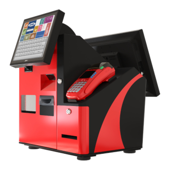
Chapter 2 Getting Started System Overview Front View Rear View Side View Page: 2-3 PA-1922 SERIES USER MANUAL... - Page 12 Chapter 2 Getting Started 10.4" Customer Touch Display Maintenance Door Reserved space for "Credit Card Reader" Printer Drawer 15" Sales Clerk Touch Panel-PC Maintenance Cover Page: 2-4 PA-1922 SERIES USER MANUAL...
- Page 13 Chapter 2 Getting Started For PAYMENT Device Barcode Reader Coin Acceptor Scan Insert Coin Credit Card Bill Acceptor Reader Insert Cash Credit Card (customer consign) Change area Thermal printer Get change back Get receipt Page: 2-5 PA-1922 SERIES USER MANUAL...
- Page 14 Chapter 2 Getting Started CAUTION FOR YOUR TROUBLESHOOTING NEEDS, CONSULT THESE MODULES’ USER’S GUIDES INCLUDED IN PA-1922 USER MANUAL FILE, AS LISTED BELOW. YOU MAY ALSO CONTACT OUR SERVICE WINDOW FOR TECHNICAL ASSISTANCE. 01. 2D Scanner_RIOTEC FS5022J 02. Touch Monitor_10.4 inch PHISTEK P104VR 03.
-
Page 15: System Specifications
PDF417, MicroPDF417, DataMatrix, QR Code, MaxiCode Environment CE / FCC EMC & Safety 0° C ~ 35° C Operating Temp. -20° C ~ 60° C Storage Temp. 20%~ 90% Humidity Certificate CE, CE-LVD, FCC Page: 2-7 PA-1922 SERIES USER MANUAL... -
Page 16: Plug In Ac Power Cord
Fixing screws Maintenance Cover Step 1. Release 3 x "fixing screws" (see above) and open the Maintenance Cover. Step 2. Plug in AC Power Cord and LAN cable as shown. LAN Cable AC Power Cord Page: 2-8 PA-1922 SERIES USER MANUAL... -
Page 17: Feed / Take Notes
Insert paper notes into Recycler for future payout preparation in the direction shown. (red arrow) Step 3. Lock Draw out the cash box to Bank withdraw the paper notes. Note Step 2. Cash Box Page: 2-9 PA-1922 SERIES USER MANUAL... -
Page 18: Feed / Take Coins
"Coin Lock Hopper". Pulling Handle Step 3. Press the "Push Button" on the Coin Hopper and slide to remove the top cover. Step 4. Feed or take Coins into/from the Coin Push Hopper. Button Page: 2-10 PA-1922 SERIES USER MANUAL... -
Page 19: Change Printer Paper
Paper Holder Open Close Step 3. Close the "Paper Holder" and then change the thermal paper roll (section type). ※ Make sure the "Paper Holder" is closed before you feed paper. Page: 2-11 PA-1922 SERIES USER MANUAL... - Page 20 Chapter 2 Getting Started 2.5 Cable Map Page: 2-12 PA-1922 SERIES USER MANUAL...
-
Page 21: Cabel Lock Position Of Cube-Body
Chapter 2 Getting Started 2.6 Cable Lock Position of Cube-body Page: 2-13 PA-1922 SERIES USER MANUAL... -
Page 22: Cabel Illustrations
Side B to 24V/72W Power adaptor AC inlet port Side A Side C to 24V/90W Power adaptor AC inlet port fixing on Rear I/O bracket Side D to 12V/60W Power adaptor AC inlet port Page: 2-14 PA-1922 SERIES USER MANUAL... - Page 23 Chapter 2 Getting Started Cable_2 Drawing PN: 52-002-10530001 DC outlet for connecting 60W /12V Power adaptor to Power sharing cable. Cable Path Side A link from Cable_1 Side D Side B to Cable_3 Side A Page: 2-15 PA-1922 SERIES USER MANUAL...
- Page 24 PN: 27-012-38303111 for sharing DC12V power to 3 devices. Cable Path Side A Side D to Cable_4 Side A link from 12V/60W Power Side E to Cable_5 Side A adaptor DC outlet port Side F to Cable_6 Side A Page: 2-16 PA-1922 SERIES USER MANUAL...
- Page 25 Chapter 2 Getting Started Cable_4 Drawing PN: 27-012-38314111 for providing DC12V to Coin Acceptor. Cable path Side A link from Cable_3 Side E Side B to Coin Acceptor 6-pin pulse port Page: 2-17 PA-1922 SERIES USER MANUAL...
- Page 26 Chapter 2 Getting Started Cable_5 Drawing PN: 27-012-37320111 for providing DC12V & RS-232 to Vega-RC Note Acceptor. Cable path Side B to Cable_13 Side B Side A link to Note acceptor Side C to Cable_3 Side D Page: 2-18 PA-1922 SERIES USER MANUAL...
- Page 27 Drawing PN: 27-012-38329111 for providing DC12V & USB to NV11 Note Acceptor. Cable Path Side C to Cable_3 Side D Side A link to NV11 Note Acceptor Side B to USB hub port 2 Page: 2-19 PA-1922 SERIES USER MANUAL...
- Page 28 Chapter 2 Getting Started Cable_7 Drawing 52-002-04095302 DC outlet for 90W/24V Power adaptor connected to 15” Touch Panel-PC DC-In Cable path Side A link from Cable_1 Side C Side B to PA-6322-PPC DC-In Page: 2-20 PA-1922 SERIES USER MANUAL...
- Page 29 Side A link from Cable_1 Side B Side B link to Cable_21 Side A Cable_21 27-012-38302111 for 52-002-04095302 Power DC outlet connector adaptor Side A link from Cable_8 Side B Side B link to Hopper DC-In Cable Path Page: 2-21 PA-1922 SERIES USER MANUAL...
- Page 30 Chapter 2 Getting Started Cable_9 Drawing PN: 27-012-38319111 for providing 12V Power to 10.4” display. Cable Path Side A link to 10.4” touch display DC-In Side B from PA-6322-PPC DC-out 12V Page: 2-22 PA-1922 SERIES USER MANUAL...
- Page 31 Chapter 2 Getting Started Cable_10 Drawing PN: 27-012-38327111, for providing 24V Power to Thermal Printer. Cable Path Side A link to 3” Printer Control /B CN1 Side B from PA-6322-PPC DC-out 24V Page: 2-23 PA-1922 SERIES USER MANUAL...
- Page 32 Chapter 2 Getting Started Cable_11 Drawing PN: An attachment of Coin acceptor for 15” Touch panel-PC RS-232 to Coin Acceptor. Cable Path Side A link to Cable_12 Side B Side B to Coin Acceptor RS-232 port Page: 2-24 PA-1922 SERIES USER MANUAL...
- Page 33 Chapter 2 Getting Started Cable_12 Drawing PN: 27-024-38312032 for connecting 15” Touch Panel-PC RS-232 to Coin Acceptor. Cable Path Side A link to PA-6322-PPC COM1 Side B to Cable_11 Side A Page: 2-25 PA-1922 SERIES USER MANUAL...
- Page 34 Chapter 2 Getting Started Cable_13 Drawing PN: 27-024-38312031 for connecting 15” Touch Panel-PC RS-232 to Coin Acceptor. Cable Path Side A link to PA-6322-PPC COM2 Side B to Cable_5 Side B Page: 2-26 PA-1922 SERIES USER MANUAL...
- Page 35 Drawing PN: An attachment of USB 3.0 Hub kit for 15” Touch Panel-PC USB3.0 to USB 3.0 Hub Cable Path Side A link to PA-6322-PPC USB1 Side B to USB 3.0 Hub USB input Page: 2-27 PA-1922 SERIES USER MANUAL...
- Page 36 Chapter 2 Getting Started Cable_15 Drawing PN: 52-820-50220107 USB cable for connecting USB 3.0 Hub to Scanner. Cable Path Side A link to USB Hub port 1 Page: 2-28 PA-1922 SERIES USER MANUAL...
- Page 37 Chapter 2 Getting Started Cable_16 Drawing PN: 27-006-38317111 for connecting 15” Touch Panel-PC USB port to Coin Hopper USB. Cable Path Side A link to PA-6322-PPC USB2 port Side B to Coin Hopper USB Page: 2-29 PA-1922 SERIES USER MANUAL...
- Page 38 Chapter 2 Getting Started Cable_17 Drawing PN: 27-006-38317112 for connecting 15” Touch Panel-PC USB to 10.4” touch display. Cable Path Side A link to 10.4” Touch display USB Side B link from PA-6322-PPC USB3 Page: 2-30 PA-1922 SERIES USER MANUAL...
- Page 39 Chapter 2 Getting Started Cable_18 Drawing PN: 27-006-30224111 for connecting 15” Touch Panel-PC USB to 3” Printer USB. Cable Path Side A link PA-6322-PPC USB4 Side B to Printer Control /B CN21 Page: 2-31 PA-1922 SERIES USER MANUAL...
- Page 40 Chapter 2 Getting Started Cable_19 Drawing PN: 27-017-38324111 for connecting 15” Touch Panel-PC VGA to 10.4” display. Cable Path Side A link fromPA-6322-PPC VGA Side B to 10.4” Touch LCD VGA Page: 2-32 PA-1922 SERIES USER MANUAL...
- Page 41 Chapter 2 Getting Started Cable_20 Drawing PN: 27-026-38307111 for connecting 15” Touch Panel-PC LAN to LAN extending connector. Cable path LAN extending connector Side A link from PA-6322-PPC LAN Side B to Page: 2-33 PA-1922 SERIES USER MANUAL...
- Page 42 Chapter 2 Getting Started Cable_22 Drawing PN: 27-012-38312111 for providing DC12V & RS-232 to NE77 Note Acceptor. Cable Path Side B to Cable_13 Side B Side A link to Note acceptor Side C to Cable_3 Side D Page: 2-34 PA-1922 SERIES USER MANUAL...
-
Page 43: Safety Precautions
Avoid exposure to sunlight for a long period of time (for example, in a closed car in summer time. Also avoid the system from any heating device.). Or do not use the PA-1922 when it has been left outdoors in a cold winter day. -
Page 44: System Configuration
System Configuration This chapter contains helpful information about the various component modules comprised in PA-1922 as well as the BIOS operation. PA-1922 consists of the component modules as below: • 01. 2D Scanner_RIOTEC FS5022J • 02. 10.4 Inch Touch Monitor_PHISTEK P104VR •... -
Page 45: D Scanner_Riotec Fs5022J
Chapter 3 System Configuration 3-1. 01. 2D Scanner_RIOTEC FS5022J Page: 3-2 PA-1922 SERIES USER MANUAL... -
Page 46: Inch Touch Monitor_Phistek P104Vr
VGA D-Sub 15 pins, DC 12V Power consumption Temp 0~40 degrees C / -10~50 degrees C (Operation/Storage) Humidity 20% to 90% non-condensing Certificate CE , FCC, BSMI Five-Wire Analog Resistive Resistive Touch Panel USB type, eGalax Touch Control Drive Page: 3-3 PA-1922 SERIES USER MANUAL... - Page 47 1. Be sure to ground the frame ground of the BA-T500II by installing screws. 2. Be sure to connect all four pins. 15-pin FFC connector for the printer Printer mechanism Connector 26-pin FFC connector for the thermal print head Interface CN21 Connector Page: 3-4 PA-1922 SERIES USER MANUAL...
-
Page 48: Inch Printer_Epson Kit
Paper ※ Make sure the "Paper Holder" Holder is closed before you feed paper. CAUTION FOR YOUR TROUBLESHOOTING NEEDS, CONSULT THE "3-Inch Printer_EPSON Kit" ATTACHED DOCUMENT of "PA-1922 e-MANUAL” OR CONTACT OUR SERVICE WINDOW. Page: 3-5 PA-1922 SERIES USER MANUAL... - Page 49 Table 4 LED Flashes Status Green Orange Power ON If the problem persists after the INHIBIT corrected actions are taken, Flashes I/O Test Mode contact ICT or agents for technical support. Page: 3-6 PA-1922 SERIES USER MANUAL...
- Page 50 EURO /OFF /OFF /OFF /OFF /OFF € € SW default: 2 supported pence pence pence pound /OFF /OFF /OFF /OFF £ SW default: 2 supported 5/10 cents cents dollar /OFF /OFF /OFF /OFF /OFF Page: 3-7 PA-1922 SERIES USER MANUAL...
-
Page 51: Coin Acceptor Ict Uca
Chapter 3 System Configuration CAUTION FOR MORE INFORAMATION AND YOUR TROUBLESHOOTING NEEDS, PLEASE SEE THEDOCUMENT "04. Coin Acceptor ICT UCA" of "PA-1922 e-MANUAL" OR CONTACT OUR SERVICE WINDOW. Page: 3-8 PA-1922 SERIES USER MANUAL... -
Page 52: Coin Hopper_Innovative Smart Hopper
Slide Hopper Off Remove the hopper from the mounting plate. CAUTION FOR MORE INFORMATION AND YOUR TROUBLESHOOTING NEEDS, PLEASE SEE THE ATTACHED DOCUMENT "05. Coin Hopper_Innovative SMART Hopper" of "PA-1922 e-MANUAL" or CONTACT OUR SERVICE WINDOW. Page: 3-9 PA-1922 SERIES USER MANUAL... - Page 53 Memory checksum error Re-download hopper firmware. If this persists return to ITL for service. 8 Flashes Hopper sensors not initialised Return to ITL for service. 9 Flashes Legacy, no longer used. (Lid removed). Status LED’s Page: 3-10 PA-1922 SERIES USER MANUAL...
-
Page 54: Note Acceptor_Innovative Nv11
5 Flashes, pause (repeated) Motor Timeout Note Float Status LED codes CAUTION FOR MORE IFNORMATION AND YOUR TROUBLESHOOTING NEEDS, PLEASE SEE THE ATTACHED DOCUMENT "06. Note Acceptor_Innovative NV11" of "PA-1922 e-MANUAL" or CONTACT OUR SERVICE WINDOW. Page: 3-11 PA-1922 SERIES USER MANUAL... -
Page 55: Note Acceptor_Jcm Vega-Rc Twin
Error occurs LED Pattern Color Indications Error (Machine Lock) CAUTION FOR MORE INFORMATION AND YOUR TROUBLESHOOTING NEEDS, PLEASE SEE THE ATTACHED DOCUMENT "07. Note Acceptor_JCM Vega-RC Twin" of "PA-1922 e-MANUAL" or CONTACT OUR SERVICE WINDOW. Page: 3-12 PA-1922 SERIES USER MANUAL... - Page 56 Clean the bill box. Check and make sure all the cables on NE77-BR Recycle Comm_Error Validator and Recycler are connected properly. Inspect the foreign objects on sensors or bill path Motor Error and clean them. Page: 3-13 PA-1922 SERIES USER MANUAL...
-
Page 57: Note Acceptor_Ict Ne77
SGD2 SGD5 SGD10 SGD50 TWD200 TWD100 TWD1000 & TWD500 CAUTION FOR MORE INFORMATION AND YOUR TROUBLESHOOTING NEEDS, PLEASE SEE THE ATTACHED DOCUMENT "08. Note Acceptor_ICT NE77_Guide" of "PA-1922 e-MANUAL" or CONTACT OUR SERVICE WINDOW. Page: 3-14 PA-1922 SERIES USER MANUAL... -
Page 58: Inch Panel-Pc_Prox Pa-6322-Ppc
ISO I ,II, III; JIS I,II and support information key reader Fingerprint 8-bit grayscale reader CAUTION FOR MORE INFORMATION AND YOUR TROUBLESHOOTING NEEDS, PLEASE SEE THE ATTACHED DOCUMENT "09. 15-Inch Panel-PC_Prox PA-6322-PPC" OF "PA-1922 e-MANUAL" OR CONTACT OUR SERVICE WINDOW. Page: 3-15 PA-1922 SERIES USER MANUAL... - Page 59 Chapter 3 System Configuration Rear I/O Storage USB1 DRW1 COM2 COM1 DC In Printer 2/3/4 LAN 2nd- Power COM3 COM4 (reserved) SIDE I/O Power USB5 Button Page: 3-16 PA-1922 SERIES USER MANUAL...
- Page 60 DC-IN Port DC IN: DC Power-In Port (rear IO) ASSIGNMENT ASSIGNMENT +24V +24V DC IN VGA Port VGA: VGA Port, D-Sub 15-pin (rear IO) ASSIGNMENT ASSIGNMENT GREEN BLUE DDCA DATA HSYNC VSYNC DDCA CLK Page: 3-17 PA-1922 SERIES USER MANUAL...
- Page 61 /USB 2 USB 5: Side IO /USB 3 ASSIGNMENT ASSIGNMENT /USB 4 +5V (Max. /USB 5 current: 0.5A) Note: USB1 is built with Standby power 5V. The others do not provide the standby power. Page: 3-18 PA-1922 SERIES USER MANUAL...
- Page 62 RB Ver. LAN LED Indicator: Right:Green Left Side LED Orange Color Blinking Giga LAN Message Active Green Green Color Blinking 10/100Mbps LAN Message Active Right Side LED Green Color On LAN switch/ hub connected. Page: 3-19 PA-1922 SERIES USER MANUAL...
- Page 63 ASSIGNMENT ASSIGNMENT DRW2 Sense 12V/24V (Max. current 1A) GPIO1 /DRW1 GPIO2 /DRW2 DRW1 Sense DRW1 2nd Display Power Port DIS PWR: DC12V power supply of for 2 display ASSIGNMENT ASSIGNMENT VCC12 VCC12 DIS PWR Page: 3-20 PA-1922 SERIES USER MANUAL...
-
Page 64: Software Utilities
3. 3” Printer Module EPSON M-T532IIAP Kit 4. Coin Acceptor ICT UCA 5. Coin Hopper Innovative SMART 6. Note Acceptor Innovative NV11 7. Note Acceptor JCM Vega-RC Twin 8. Note Acceptor ICT NE77 9. Panel PC PA-6322-PPC • BIOS Operation Page: 4-1 PA-1922 SERIES USER MANUAL... - Page 65 Chapter 4 Software Utilities 4.1. Driver & SDK Introduction Enclosed with the PA-1922 Series package is our “DRIVER & SDK”, which comes in a DVD-ROM format. 1. RIOTEC FS5022J 1D /2D Scanner \Modules\01. 2D Scanner_RIOTEC FS5022J Folder Files Description RIOTEC FS5022J.pdf Specification 2.
- Page 66 SPP guide \SDK\TestUtility PIPS_2_3_3.msi Test utility _Pips NVXUSB,NV200,BV100,SH,SPO - 32 bit USB driver. Please - USB Driver.zip install communication USB Driver utility before you NVXUSB,NV200,BV100,SH,SPO - 64 bit install the driver. - USB Driver.zip Page: 4-3 PA-1922 SERIES USER MANUAL...
- Page 67 JCM VEGA Operation and Maintenance Guide Rev 2 2013.pdf VEGA-RC-Twin-Operation-and-Maintena Guide nce-Manual.pdf \SDK\Document Guide VEGA_Quick_Reference.pdf Guide VEGA-Training-Overview.pdf ID003_RC_CommunicationSpecification CommunicationSpecification (22.09.2011).pdf \SDK\Document ID03-001E(Rev05) Communication CommunicationSpecification Spec.pdf \SDK\Demo JCM DemoProject Visual Studio 2010 Project Demo Project Page: 4-4 PA-1922 SERIES USER MANUAL...
-
Page 68: Bios Operation
These elements provide standard environment for booting an operating system and running pre-boot applications. The following diagram shows the Extensible Firmware Interface’s location in the software stack. Page: 4-5 PA-1922 SERIES USER MANUAL... - Page 69 Accessing Setup Utility When the system is powered on, the BIOS will enter the Power-On Self-Test (POST) routines and the following message will appear on the lower screen: POST Screen with AMI Logo Page: 4-6 PA-1922 SERIES USER MANUAL...
- Page 70 English. You may use <↑> or <↓> key to select among the items and press <Enter> to confirm and enter the sub-menu. The following table provides the list of the navigation keys that you can use while operating the BIOS setup menu. Page: 4-7 PA-1922 SERIES USER MANUAL...
- Page 71 The CMOS battery is The battery may be losing power and users should bad or has been replace the battery immediately. Also, this message is displayed once the new battery is recently replaced. replaced. Page: 4-8 PA-1922 SERIES USER MANUAL...
-
Page 72: Main
Displays the current TXE Version Version System English BIOS Setup language. Language System Date month, day, year Sets the system date. The format is [Day Month/ Date/ Year]. Users can directly enter values or use <+> or <-> Page: 4-9 PA-1922 SERIES USER MANUAL... -
Page 73: Advanced
F81866 Super IO Sub-Menu System Super IO Chip parameters. Configuration Hardware Monitor Sub-Menu Monitor hardware status. F81866 Watchdog Sub-Menu F81866 Watchdog parameters. CPU Configuration Sub-Menu CPU Configuration Parameters. IDE Configuration Sub-Menu SATA Configuration Parameters. Page: 4-10 PA-1922 SERIES USER MANUAL... -
Page 74: Advanced - Acpi Settings
Menu Path Advanced > ACPI Settings The ACPI Settings allows users to configure relevant ACPI (Advanced Configuration and Power Management Interface) settings, such as ACPI Sleep State, Hibernation, lock legacy resources, etc. ACPI Settings Screen Page: 4-11 PA-1922 SERIES USER MANUAL... -
Page 75: Advanced - F81866 Super Io Configuration
Configure the parameters of Serial Port 4 Configuration (COMD). Parallel Port Sub-menu Configure the parameters of Parallel Port Configuration (LPT/LPTE). Cash Drawer -Cash Drawer 12V Cash Drawer 12V or 24V selection -Cash Drawer 24V Page: 4-12 PA-1922 SERIES USER MANUAL... - Page 76 Allows you to select specific -IO=3F8h; IRQ=4; IO address and IRQ for Serial -IO=3F8h; IRQ=3,4,5,6,7,9,10,11,12; Port 1. -IO=2F8h; IRQ=3,4,5,6,7,9,10,11,12; -IO=3E8h; IRQ=3,4,5,6,7,9,10,11,12; -IO=2E8h; IRQ=3,4,5,6,7,9,10,11,12; COM1 Voltage -Disabled Disables or selects 12V/5V select -12V voltage for COM1. Page: 4-13 PA-1922 SERIES USER MANUAL...
- Page 77 Displays the current settings of Serial Port 2. Change Settings -Auto Allows you to select specific -IO=2F8h; IRQ=3; IO address and IRQ for -IO=3F8h; IRQ=3,4,5,6,7,9,10,11,12; Serial Port 2. -IO=2F8h; IRQ=3,4,5,6,7,9,10,11,12; -IO=3E8h; IRQ=3,4,5,6,7,9,10,11,12; -IO=2E8h; IRQ=3,4,5,6,7,9,10,11,12; Page: 4-14 PA-1922 SERIES USER MANUAL...
- Page 78 Displays the current settings of Serial Port 3. Change settings -Auto Allows you to select specific -IO=3E8h; IRQ=7; IO address and IRQ for -IO=3E8h; IRQ=3,4,5,6,7,9,10,11,12; Serial Port 3. -IO=2E8h; IRQ=3,4,5,6,7,9,10,11,12; -IO=2F0h; IRQ=3,4,5,6,7,9,10,11,12; -IO=2E0h; IRQ=3,4,5,6,7,9,10,11,12; Page: 4-15 PA-1922 SERIES USER MANUAL...
- Page 79 Allows you to select specific -IO=2E8h; IRQ=10; IO address and IRQ for -IO=3E8h; IRQ=3,4,5,6,7,9,10,11,12; Serial Port 2. -IO=2E8h; IRQ=3,4,5,6,7,9,10,11,12; -IO=2F0h; IRQ=3,4,5,6,7,9,10,11,12; -IO=2E0h; IRQ=3,4,5,6,7,9,10,11,12; COM4 Voltage -Disabled Disables or selects 12V/5V select -12V voltage for COM4. Page: 4-16 PA-1922 SERIES USER MANUAL...
- Page 80 -IO=3BCh; IRQ=5,6,7,9,10,11,12 Device Mode -STD Printer Mode Changes the printer port mode. -SPP Mode -EPP-1.9 and SPP Mode -EPP-1.7 and SPP Mode -ECP Mode -ECP and EPP 1.9 Mode -ECP and EPP 1.7 Mode Page: 4-17 PA-1922 SERIES USER MANUAL...
-
Page 81: Advanced - Hardware Monitor
No changeable options Detects and displays 12V voltage. VCC3V No changeable options Detects and displays 3V voltage. VSB3V No changeable options Detects and displays VSB3V voltage. VBAT No changeable options Detects and displays the battery voltage. Page: 4-18 PA-1922 SERIES USER MANUAL... -
Page 82: Advanced - F81866 Watchdog
Selects 1s (second) or 60s (minute) as timer unit -60s the time unit of Watchdog timer. Count for Timer multiple options Sets the timeout for Watchdog timer. (Seconds) ranging from 1 to 255 (Max. value: 255 seconds or minutes) Page: 4-19 PA-1922 SERIES USER MANUAL... -
Page 83: Advanced - Cpu Configuration
BIOS Setting Options Description/Purpose Socket 0 Sub-Menu Reports CPU Information Information CPU Speed No changeable Reports the current CPU speed. options 64-bit No changeable Reports if the processor supports Intel x86-64 options (amd64) implementation. Page: 4-20 PA-1922 SERIES USER MANUAL... - Page 84 Reports if Intel VT-x Technology is supported by the processor. Intel VT-x No changeable options Previously codenamed "Vanderpool", VT-x Technology represents Intel’s technology for virtualization on the x86 platform. Utilizing Vanderpool Page: 4-21 PA-1922 SERIES USER MANUAL...
-
Page 85: Advanced - Ide Configuration
- Port0 ODD SATA ODD is Port0 or Port1 Port - Port1 ODD - No ODD SATA Mode - IDE mode Configures SATA as follows: - AHCI mode IDE: Set SATA operation mode to IDE mode. Page: 4-22 PA-1922 SERIES USER MANUAL... -
Page 86: Advanced - Os Selection
- Windows 7 If you use Windows 8 with UEFI and GPT - Windows 8 partition, please select Windows 8 UEFI. - Windows 8 UEFI Limitation: DOS is unbootable under Windows 8 UEFI mode. Page: 4-23 PA-1922 SERIES USER MANUAL... -
Page 87: Advanced - Csm Configuration
- UEFI and Legacy This option controls the kind of devices the filter - Legacy only system can boot. - UEFI only Network - Do not launch Controls the execution of UEFI or Legacy PXE Page: 4-24 PA-1922 SERIES USER MANUAL... -
Page 88: Advanced - Usb Configuration
Sets to “Enabled” if you want to use USB Support - Enabled devices with the legacy operating systems that - Auto do not support USB. XHCI Hand-off - Disabled This is a workaround for OSes without XHCI Page: 4-25 PA-1922 SERIES USER MANUAL... - Page 89 1 to 40 second increments in seconds Mass Storage - Auto Displays the device name and chooses the Devices: - Floppy device emulation type. - Force FDD - Hard Disk - CD-ROM Page: 4-26 PA-1922 SERIES USER MANUAL...
-
Page 90: Chipset
Chapter 4 Software Utilities 4.2.3 Chipset Menu Path Chipset Chipset Menu Screen BIOS Setting Options Description/Purpose North Bridge Sub-menu Sets the Parameter for (North Bridge) configuration. South Bridge Sub-menu Sets the Parameter for (South Bridge) configuration. Page: 4-27 PA-1922 SERIES USER MANUAL... -
Page 91: North Bridge
Allows users to execute the LCD Control. Memory No changeable options Displays the DRAM information on the Information platform. Total Memory No changeable options Displays the DRAM size. Memory Slot0 No changeable options Memory in the slot 0. Page: 4-28 PA-1922 SERIES USER MANUAL... - Page 92 LCD Control Screen BIOS Setting Options Description/Purpose Primary IGFX - CRT Selects the Primary Display Device. Boot Display - LVDS Secondary - Disabled Selects the Secondary Display Device. IGFX Boot - CRT Display - LVDS Page: 4-29 PA-1922 SERIES USER MANUAL...
-
Page 93: South Bridge
Power On: The system is turned on after the AC • power is restored to the board. Last State: It will bring the system back to the • power state when AC power was lost. Page: 4-30 PA-1922 SERIES USER MANUAL... -
Page 94: Security
Setup utility. Security Menu Screen BIOS Setting Options Description/Purpose Administrator Password can be Specifies the administrator password. Password 3-20 alphanumeric characters. User Password can be Specifies the user password. Password 3-20 alphanumeric characters. Page: 4-31 PA-1922 SERIES USER MANUAL... - Page 95 Security menu and press <Enter>, and the password dialog entry box appears. 2. Select the configured Administrator Password or User Password that you want to delete. Leave the dialog box blank and press <Enter>. 3. Press <Enter> again when the password confirmation box appears. Page: 4-32 PA-1922 SERIES USER MANUAL...
-
Page 96: Boot
Boot Option - [Drive(s)] Allows users to change the boot order #1~#n - Disabled from the available device(s). Note that Page: 4-33 PA-1922 SERIES USER MANUAL... -
Page 97: Save & Exit
Discard Changes and Reset to discard any changes you have made and restore the factory BIOS defaults. Load User Defaults You may simply press F3 at any time to load the Optimized Values which resets all BIOS settings to the factory defaults. Page: 4-34 PA-1922 SERIES USER MANUAL... - Page 98 Resets the system without saving any changes Changes and configured in BIOS settings. Reset Restore No changeable options Loads the optimized defaults for BIOS settings. Defaults Boot Override - [Drive(s)] Forces to boot from selected [drive(s)]. Page: 4-35 PA-1922 SERIES USER MANUAL...
-
Page 99: Configuring Watchdog Timer
; ------------------------- Enter to extended function mode mov al, 87h out dx, out dx, ; ----------------------- Select Logical Device 7 of watchdog timer mov al, out dx, out dx, ;---------------------------------Enable Watch dog feature 030h mov al, out dx, Page: 4-36 PA-1922 SERIES USER MANUAL... - Page 100 ; ----------- Set timeout interval as 30seconds and start counting --- mov al, 0f6h out dx, mov al, ;---------------------------------Exit the extended function mode dec dx 0aah out dx, Page: 4-37 PA-1922 SERIES USER MANUAL...
-
Page 101: Flash Bios Update
(4) Select [Boot] menu as the picture shown below. (5) Select [Hard Drive BBS Priorities] and set the USB bootable device as the 1st boot device. (6) Press F4 to save the configuration and exit the BIOS setup menu. Page: 4-38 PA-1922 SERIES USER MANUAL... - Page 102 BIOS ROM and the system will be unable to boot up next time. After the BIOS update is completed, the messages from AFUDOS utility will be shown as below: Page: 4-39 PA-1922 SERIES USER MANUAL...
- Page 103 Restart the system and boot up with the new BIOS configurations. The BIOS Update is completed after the system is restarted. Reboot the system and verify if the BIOS version shown on the initialization screen has been updated. Page: 4-40 PA-1922 SERIES USER MANUAL...
-
Page 104: Optional Devices For Pa-6322
(3) Follow the wizard instructions to complete the installation. Launch the Program The steps below guide you to load the Prox-PMP3000 program. (1) Click the MSR folder from the path: Start/Programs/Protech OPOS. (2) Click Prox-PMP3000 to launch the program. Page: 4-41... - Page 105 Select the COM port number from the drop-down list. (only for UART/USB interface). AutoDisable (check box) Check to disable the device automatically when data is received. (check box) Enable to trigger FreezeEvents, and the FreezeEvents application will not allow events to be delivered. Page: 4-42 PA-1922 SERIES USER MANUAL...
- Page 106 Set decode data properties applicable. ParseDecodeData Set parse decode data properties TransmitSentinels Set transmit-sentinels properties ErrorReporting Type Card, track TracksToRead Track1, track2, track3, tracks12, tracks13, tracks14, tracks23, tracks24, tracks34, tracks123, tracks124, tracks134, tracks234, tracks1234 (Tracks4 is not applicable). Page: 4-43 PA-1922 SERIES USER MANUAL...
- Page 107 (Row) Display the data of all tracks (Track4 is not applicable). (5) Parsed Data tab items Button/Item Description Parsed Data Display special properties. MB301X Type (RS232/PS2) Key Name Type Default Value Note default string PMP3000 OPOS S.O Link Page: 4-44 PA-1922 SERIES USER MANUAL...
-
Page 108: Msr: Giga-Tms Mjr243 (Rs-232)
Device Name for CO open FileName (NULL) (reserved) HardwareProvider (reserved) Model MJR243 Device model name Parity None Parity for the communication port Port COM4 COM Port Protocol Hardware Communication Control Baudrate 19200 RS-232 baudrate Page: 4-45 PA-1922 SERIES USER MANUAL... - Page 109 DiscretionaryData Properties specific binary Track2 Read only Supported DiscretionaryData Properties specific bool TransmitSentinels Supported Methods common Open Supported Methods common Close Supported Methods common Claim Supported Methods common ClaimDevice Supported Methods common Release Supported Page: 4-46 PA-1922 SERIES USER MANUAL...
- Page 110 Read Only Surname ○ Read Only Title ○ Read Only Track1Data ○ Read Only Track1DiscretionaryData ○ Read Only Track2Data ○ Read Only Track2DiscretionaryData ○ Read Only Track3Data ○ Read Only TracksToRead ○ TransmitSentinels ○ Page: 4-47 PA-1922 SERIES USER MANUAL...
-
Page 111: Opos Msr Register
2. Launch the Program The steps below guides you how to load the OPOS MSR Register program. (1) Click the OPOS folder from the path: Start/Programs/GIGA‐TMS. (2) Click OPOS MSR Register to launch the program. Page: 4-48 PA-1922 SERIES USER MANUAL... - Page 112 Step 1 Select an item in the Service Object List box from the left pane. Make sure the correct item is selected. Step 2 Click Reg button Step 3 In the OPOS MSR Setting screen, enter the device name and click OK. Page: 4-49 PA-1922 SERIES USER MANUAL...
- Page 113 Chapter 4 Software Utilities (3) Example 1. MAGTEK USB HID (4) Example 2. PROMAG MSR/MJR PART‐NO, Keyboard mode. Page: 4-50 PA-1922 SERIES USER MANUAL...
- Page 114 (reserved) HardwareProvider string (reserved) Model string MJR243 Device model name Parity string None Parity for the communication port Port string COM4 COM Port Number Protocol string Hardware Communication Control Baudrate string 19200 RS-232 baudrate Page: 4-51 PA-1922 SERIES USER MANUAL...
- Page 115 Surname Read only Supported Properties specific string Title Read only Supported Properties specific binary Track1Data Read only Supported Properties specific binary Track1 Read only Supported DiscretionaryData Properties specific binary Track2Data Read only Supported Page: 4-52 PA-1922 SERIES USER MANUAL...
-
Page 116: Opos Msr Tester
2. Launching the Program The steps below guide you to load the OPOS MSR Tester program. (1) Click the OPOS folder from the path: Start\Programs\GIGA‐TMS (2) Click OPOS MSR Tester to launch the program. Page: 4-53 PA-1922 SERIES USER MANUAL... - Page 117 Chapter 4 Software Utilities 3. Configuration for OPOS MSR Tester Program (1) See the picture below for Main screen buttons/items: Page: 4-54 PA-1922 SERIES USER MANUAL...
- Page 118 (2) To get the track data using OPOS driver, follow the steps below: Step 1 Enter the Device Name. Step 2 Click Open button. Step 3 Swipe the card to get the track data. (3) Example 1. MAGTEK USB HID. Page: 4-55 PA-1922 SERIES USER MANUAL...
- Page 119 Chapter 4 Software Utilities (4) Example 2. PROMAG MSR/MJR PART‐NO, Keyboard mode (5) Example 3. PROMAG MSR PART‐NO, HID mode Page: 4-56 PA-1922 SERIES USER MANUAL...
-
Page 120: Optional Fingerprint Driver Utility
Click Setup.exe file for driver installation. Step 4 Follow the on-screen instructions to complete the installation. Step 5 Once the installation is completed, shut down the system and restart PA-6322 (Panel PC) for the changes to take effect. Page: 4-57 PA-1922 SERIES USER MANUAL... -
Page 121: System Diagrams
System Diagrams This chapter includes the exploded diagrams of the system and the parts list as well as the part numbers of the PA-1922 system. Exploded Diagrams for Panel PC • Page: 5-1 PA-1922 SERIES USER MANUAL... - Page 122 Chapter 5 System Diagrams Component Name P/N No. Q’ty M4 x 15L 22-232-40015211 PLASTIC FOOT 90-004-28100000 PA-1922-BASE-A 20-032-02061383 Pull Handle 30-080-08110284 PA-1922-BASE-ASSY 20-032-02062383 PA-1922-CASE-PB-4 20-001-03001383 M4 x 6L 22-215-40006011 PA-1922-STOP-BOARD 20-006-03009383 M4 x 5L 22-235-40005911 Page: 5-2 PA-1922 SERIES USER MANUAL...
- Page 123 Chapter 5 System Diagrams Component Name P/N No. Q’ty PRINTER SLIDE BOARD C 20-006-02001383 Full Extension Drawer Slide 20-058-31001284 1 set SCREWS M4 X 5L 22-235-40005911 SCREW M4 X 6L 22-215-40006011 Page: 5-3 PA-1922 SERIES USER MANUAL...
- Page 124 Component Name P/N No. Q’ty MAIN HOUSING 20-042-02061383 ADAPTER HOLDER 20-029-03003383 ADAPTER HOLDER P2 20-029-03005383 SCREW M3 x 4L 22-215-30004311 SCREW M3 x 5L 22-242-30005311 CAM LOCK 20-025-30001284 LOCK HOPPER PLATE 20-005-02001383 GROMMET (Black) 90-026-04600000 Page: 5-4 PA-1922 SERIES USER MANUAL...
- Page 125 Chapter 5 System Diagrams Component Name P/N No. Q’ty CABLE BOX FOR HUB 20-040-03001383 POWER CORD CABLE 27-013-38313111 SCREW M3 x 7L 22-235-30007011 SLIP NUTS 23-142-60601271 (M6X1.0P, H=6mm) Page: 5-5 PA-1922 SERIES USER MANUAL...
- Page 126 20-005-02002383 PRINTER PAPER SLOT 20-006-02061383 PRINTER HOLDER 20-029-02001383 FLAT HEAD SCREW#2 / 22-215-30004311 M3x0.5Px4mm PRINTER PCBA M3 x 5L 22-242-30005311 3 INCH PAPER SUPPORT ANY 20-002-03001383 HEX CU BOSS M2.5 22-298-25010001 Thermal Printer 52-701-02025008 Page: 5-6 PA-1922 SERIES USER MANUAL...
- Page 127 52-370-10050009 WIRE MOUNT 90-023-04100383 PRINTER PCB BOX 22-040-03002383 Thin Bars Axis 22-000-30087001 (for Paper roll: 80 x 80 x 12 mm) Thick Bars Axis 22-000-35087001 (for Paper roll: 80 x 130 x 25 mm) Page: 5-7 PA-1922 SERIES USER MANUAL...
- Page 128 90-013-15100383 HOPPER COVER STOP BITS 20-004-02001383 SCREW M4 x 4L 22-272-40004911 SCREW M3 x 5L 22-235-30005011 SNAP RIVET 90-042-04102000 CABLE COVER 20-004-02062383 CABLE COVER SMALL 20-004-02063383 CABLE CLAMP 90-023-04700000 SCREW M4 x 8L 22-245-40008011 Page: 5-8 PA-1922 SERIES USER MANUAL...
- Page 129 Chapter 5 System Diagrams Component Name P/N No. Q’ty LAN CONNECTOR SCREW M3 x 5L 22-242-30005311 VELCRO TAPE 30-082-04200000 SERVICE COVER 20-004-02065383 SCREW M3 x 5L 22-215-30005011 Page: 5-9 PA-1922 SERIES USER MANUAL...
- Page 130 Chapter 5 System Diagrams Component Name P/N No. Q’ty ADAPTER HOLDER ANY 20-029-03004383 ADAPTER EA10953E HOLDER 20-029-03001383 SCREW M3 x 4L 22-215-30004311 Page: 5-10 PA-1922 SERIES USER MANUAL...
- Page 131 PAN HEAD SCREW M3 x 0.5P x 8mm 22-232-30008811 SCREW M4 x P0.7 x L8 22-245-40008011 M4 x 10mm Round_head Spring 22-232-40010211 Washer SCREW/M3 x 0.5P x 6mm 22-232-30060211 M3 x 6_FH_PHI_#2_HD5_NA_MI_BO 22-215-30006311 2ND_DIS Module M4 x 0.7P x 15mm 22-232-40015211 Page: 5-11 PA-1922 SERIES USER MANUAL...
- Page 132 30-013-24100314 M4 x 10mm Round_head Spring Washer 22-232-40010211 SCREW/M3 x 0.5P x 6mm 22-232-30060211 M3x6_FH_PHI_#2_HD5_NA_MI_BO 22-215-30006311 SCREW M5 x 0.8P L=15mm ROUND 22-232-50015011 HEAD (NI) SCREW/M3 x 0.5P x 12mm 22-275-30010011 PA-6322 PPC Module Page: 5-12 PA-1922 SERIES USER MANUAL...
- Page 133 Chapter 5 System Diagrams Component Name P/N No. Q’ty PA-1922_COIN_BRKT-A 20-006-03062383 PA-1922 180D Concealed Hinge 20-012-35001383 M4 x 10MM Round_head Spring 22-232-40010211 Washer FLAT HEAD SCREW#2/M4 x 0.7P x 22-215-40015011 15L (Black) COIN MODULE SCREWS FOR COIN MODULE Page: 5-13...
- Page 134 PA1922-PAPER_MONEY_DOUBLE_TAPE 34-026-05901383 PK-7090 PLASTIC_WHEEL (M6-SCREW) 22-281-60007001 ROUND HEAD SCREW#2/M5 x 0.8P x 8L 22-242-50008011 FSLIP NUTS (M3 x 0.5P, H=4mm) 23-142-30400801 RoHS_M4_L6_FLAT (BLACK) 22-215-40006011 PAN HEAD SCREW#2/M3 x 0.5P x 8mm 22-222-30008811 SCANNER Module Page: 5-14 PA-1922 SERIES USER MANUAL...
- Page 135 Chapter 5 System Diagrams Component Name P/N No. Q’ty PA-1922_COIN_BANKNOTE_BASE 20-032-03061383 M5 x 6_Round_Ni 22-232-50006011 SLIP NUTS (M4 x 0.7P, H=4.5mm) 23-142-40450801 HOPPER Module Page: 5-15 PA-1922 SERIES USER MANUAL...
- Page 136 FLAT HEAD SCREW M4 x 0.7P x 8mm 22-215-40008711 (Black) ROUND HEAD SCREW (#2 M4 x 0.7P, 22-235-40005911 H=5.0mm) ROUND HEAD SCREW (Black) #2 / T3 x 22-135-30006011 JCM (VEGA) Module SLIP NUTS (M4 x 0.7P, H=4.5mm) 23-142-40450801 Page: 5-16 PA-1922 SERIES USER MANUAL...
- Page 137 HEX NUTS (M4 x 0.7P, H=3mm) 23-102-40300071 FLAT HEAD SCREW M4 x 0.7P x 8mm 22-215-40008711 (Black) ROUND HEAD SCREW (#2 M4 x 0.7P, 22-235-40005911 H=5.0mm) NVII Module SLIP NUTS (M4 x 0.7P, H=4.5mm) 23-142-40450801 Page: 5-17 PA-1922 SERIES USER MANUAL...
- Page 138 Chapter 5 System Diagrams Component Name P/N No. Q’ty PA-1922-NE77_COVER_BRKT_R PA-1922-NE77_COVER_BRKT_L PA-1922-NE77_COVER_BRKT_SUPPORT PA-1922_BANKNOTE_BRKT-A 20-006-03061383 M3 x 6_FH_PHI_#2_HD5_NA_MI_BO 22-215-30006311 FLAT HEAD SCREW #2/M3 x 0.5P x 4mm 22-215-30005311 (Black) PA-1922_BANKNOTE_BRKT-VEGA 20-006-03001383 PK-7090 PLASTIC_WHEEL (M6-SCREW) 22-281-60007001 HEX NUTS (M4 x 0.7P, H=3mm)
- Page 139 USER MANUAL PA-1922 Semi-Self Service Payment Kiosk PA-1922 Z1...
- Page 140 PA-1922 15” Semi-Self Service Payment Kiosk With 10.4” Customer Touch Display COPYRIGHT NOTICE & TRADEMARK All trademarks and registered trademarks mentioned herein are the property of their respective owners. This manual is copyrighted in May 2017. You may not reproduce or transmit...
- Page 141 FCC NOTICE This equipment has been tested and found to comply with the limits for a Class A digital device, pursuant to part 15 of the FCC Rules. These limits are designed to provide reasonable protection against harmful interference when the equipment is operated in a commercial environment.
- Page 142 Contents Introduction ..................1-1 About This Manual ............1-2 Getting Stared..................2-1 Package Contents ............2-2 System Overview ............2-3 System Specifications ............ 2-7 Quick Setup ..............2-8 2.4.1 Plug In AC Power Cord ........... 2-8 2.4.2 Feed / Take Notes ............
- Page 143 06. Note Acceptor_Innovative NV11 ......3-11 07. Note Acceptor_JCM Vega-RC Twin......3-12 08. Note Acceptor_ICT NE77 ........3-13 09. 15-Inch Panel-PC_Prox PA-6980-PPC ....3-15 Software Utilities ................. 4-1 Driver & SDK ..............4-2 BIOS Operation ............. 4-6 4.2.1 Main 4-10 .................
- Page 144 Optional Devices for PA-6980 ........4-60 4.5.1 MB-3102 (PS/2) MSR OPOS Driver ...... 4-62 4.5.2 MSR: GIGA-TMS MJR243 (RS-232) ..... 4-66 4.5.2.1 Commands List ..........4-66 4.5.2.2 OPOS MSR Register ......... 4-69 4.5.2.3 OPOS MSR Tester ..........4-74 4.5.3 Optional Fingerprint Driver Utility 4-78 ........
-
Page 145: Introduction
Introduction This chapter provides the introduction for the PA-1922 Kiosk as well as the framework of the user manual. The following topics are included: • About This Manual Page: 1-1 PA-1922 SERIES USER MANUAL... -
Page 146: About This Manual
PA-1922 user manual. Chapter 2 Getting Started This chapter includes the physical illustrations, quick setup and specifications for the PA-1922 system. Read the safety reminders carefully on how to take care of your system properly. Chapter 3 System Configuration This chapter outlines the locations of the motherboard and sensor board components and their respective functions. - Page 147 Getting Started This chapter provides the information for the PA-1922 system. It describes how to set up the system quickly and outlines the system specifications. The following topics are included: • Package List • System Overview • System Diagram • Quick Setup •...
-
Page 148: Package Contents
Chapter 2 Getting Started Package Contents Item Q’ty PA-1922 Semi-Self Service Kiosk PA-1922 Quick Reference Guide Manual/Driver DVD AC Power Cord If you discover any of the items listed above are damaged or lost, please contact your local distributor immediately. -
Page 149: System Overview
Chapter 2 Getting Started System Overview Front View Rear View Side View 58.0 90.0 Page: 2-3 PA-1922 SERIES USER MANUAL... - Page 150 Chapter 2 Getting Started 10.4” Customer Touch Display Maintenance Door Reserved space for "Credit Card Printer Reader" Drawer 15" Sales Clerk Touch Panel-PC Maintenance Cover Page: 2-4 PA-1922 SERIES USER MANUAL...
- Page 151 Chapter 2 Getting Started For PAYMENT Device Barcode Reader Coin Acceptor Scan Insert Coin Credit Card Bill Acceptor Reader Insert Cash Credit Card (customer consign) Change area Thermal printer Get change back Get receipt Page: 2-5 PA-1922 SERIES USER MANUAL...
- Page 152 Chapter 2 Getting Started CAUTION FOR YOUR TROUBLESHOOTING NEEDS, CONSULT THESE MODULES’ USER’S GUIDES INCLUDED IN PA-1922 USER MANUAL FILE, AS LISTED BELOW. YOU MAY ALSO CONTACT OUR SERVICE WINDOW FOR TECHNICAL ASSISTANCE. 01. 2D Scanner_RIOTEC FS5022J 02. Touch Monitor_10.4 inch PHISTEK P104VP 03.
-
Page 153: System Specifications
2D : PDF417, MicroPDF417, DataMatrix, QR Code, MaxiCode Environment EMC & Safety CE / FCC Operating Temp. 0° C ~ 35° C Storage Temp. -20° C ~ 60° C Humidity 20%~ 90% Page: 2-7 PA-1922 SERIES USER MANUAL... - Page 154 1 x 2.5” SATA HDD 1 x 2.5” SATA SSD (Optional) Display 15” TFT XGA LCD Max. Resolution: 1024 x 768 Signal Interface: LVDS (18/24bit) Touchscreen 5-wire Analog resistive or Projected Capacitive Page: 2-8 PA-1922 SERIES USER MANUAL...
- Page 155 Brightness Resistive Touchscreen: Minimum 160 cd/m Projected Capacitive Touchscreen: • Minimum 180 cd/m Environment Operating Temperature 0˚C ~35˚C (32˚F ~95˚F) Storage Temperature -20˚C ~60˚C (-4˚F ~140˚F) Humidity 20%~90% Customer Side Page: 2-9 PA-1922 SERIES USER MANUAL...
-
Page 156: Plug In Ac Power Cord
Fixing screws Maintenance Cover Step 1. Release 3 x "fixing screws" (see above) and open the Maintenance Cover. Step 2. Plug in AC Power Cord and LAN cable as shown. LAN Cable AC Power Cord Page: 2-10 PA-1922 SERIES USER MANUAL... -
Page 157: Feed / Take Notes
Insert paper notes into Recycler for future payout preparation in the direction shown. (red arrow) Step 3. Lock Draw out the cash box to Bank withdraw the paper notes. Note Step 2. Cash Box Page: 2-11 PA-1922 SERIES USER MANUAL... -
Page 158: Feed / Take Coins
"Coin Lock Hopper". Pulling Handle Step 3. Press the "Push Button" on the Coin Hopper and slide to remove the top cover. Step 4. Feed or take Coins into/from the Coin Push Hopper. Button Page: 2-12 PA-1922 SERIES USER MANUAL... -
Page 159: Change Printer Paper
Paper Holder Open Close Step 3. Close the "Paper Holder" and then change the thermal paper roll (section type). ※ Make sure the "Paper Holder" is closed before you feed paper. Page: 2-13 PA-1922 SERIES USER MANUAL... - Page 160 Chapter 2 Getting Started 2.5 Cable Map Page: 2-14 PA-1922 SERIES USER MANUAL...
- Page 161 Chapter 2 Getting Started 2.6 Cable Lock Position of Cube-body Page: 2-15 PA-1922 SERIES USER MANUAL...
- Page 162 Side B to 24V/90W Power adaptor AC inlet port Side A Side C to 24V/90W Power adaptor AC inlet port fixing on Rear I/O bracket Side D to 12V/60W Power adaptor AC inlet port Page: 2-16 PA-1922 SERIES USER MANUAL...
- Page 163 Chapter 2 Getting Started Cable_2 Drawing PN: 52-002-10530001 DC outlet for connecting 60W /12V Power adaptor to Power sharing cable. Cable Path Side A link from Cable_1 Side D Side B to Cable_3 Side A Page: 2-17 PA-1922 SERIES USER MANUAL...
- Page 164 PN: 27-012-38303111 for sharing DC12V power to 3 devices. Cable Path Side A Side D to Cable_4 Side A link from 12V/60W Power Side E to Cable_5 Side A adaptor DC outlet port Side F to Cable_6 Side A Page: 2-18 PA-1922 SERIES USER MANUAL...
- Page 165 Chapter 2 Getting Started Cable_4 Drawing PN: 27-012-38314111 for providing DC12V to Coin Acceptor. Cable path Side A link from Cable_3 Side E Side B to Coin Acceptor 6-pin pulse port Page: 2-19 PA-1922 SERIES USER MANUAL...
- Page 166 Chapter 2 Getting Started Cable_5 Drawing PN: 27-012-37320111 for providing DC12V & RS-232 to Vega-RC Note Acceptor. Cable path Side B to Cable_13 Side B Side A link to Note acceptor Side C to Cable_3 Side D Page: 2-20 PA-1922 SERIES USER MANUAL...
- Page 167 Drawing PN: 27-012-38329111 for providing DC12V & USB to NV11 Note Acceptor. Cable Path Side C to Cable_3 Side D Side A link to NV11 Note Acceptor Side B to USB hub port 2 Page: 2-21 PA-1922 SERIES USER MANUAL...
- Page 168 Chapter 2 Getting Started Cable_7 Drawing 52-002-04095302 DC outlet for 90W/24V Power adaptor connected to 15” Touch Panel-PC DC-In Cable path Side A link from Cable_1 Side C Side B to PA-6980-PPC DC-In Page: 2-22 PA-1922 SERIES USER MANUAL...
- Page 169 Side A link from Cable_1 Side B Side B link to Cable_21 Side A Cable_21 27-012-38302111 for 52-002-04095302 Power DC outlet connector adaptor Side A link from Cable_8 Side B Side B link to Hopper DC-In Cable Path Page: 2-23 PA-1922 SERIES USER MANUAL...
- Page 170 Chapter 2 Getting Started Cable_9 Drawing PN: 27-012-38319111 for providing 12V Power to 10.4” display. Cable Path Side A link to 10.4” touch display DC-In Side B from PA-6980-PPC DC-out 12V Page: 2-24 PA-1922 SERIES USER MANUAL...
- Page 171 Chapter 2 Getting Started Cable_10 Drawing PN: 27-012-38327112 for providing 24V Power to Thermal Printer. Cable Path Side A link to 3” Printer Control /B CN1 Side B from PA-6980-PPC DC-out 24V Page: 2-25 PA-1922 SERIES USER MANUAL...
- Page 172 Chapter 2 Getting Started Cable_11 Drawing PN: An attachment of Coin acceptor for 15” Touch panel-PC RS-232 to Coin Acceptor. Cable Path Side A link to Cable_12 Side B Side B to Coin Acceptor RS-232 port Page: 2-26 PA-1922 SERIES USER MANUAL...
- Page 173 Chapter 2 Getting Started Cable_12 Drawing PN: 27-024-38312032 for connecting 15” Touch Panel-PC RS-232 to Coin Acceptor. Cable Path Side A link to PA-6980-PPC COM1 Side B to Cable_11 Side A Page: 2-27 PA-1922 SERIES USER MANUAL...
- Page 174 Chapter 2 Getting Started Cable_13 Drawing PN: 27-031-38312111 for connecting 15” Touch Panel-PC RS-232. Cable Path Side A link to PA-6980-PPC COM2 Side B to Cable_5 Side B Page: 2-28 PA-1922 SERIES USER MANUAL...
- Page 175 Drawing PN: An attachment of USB 3.0 Hub kit for 15” Touch Panel-PC USB3.0 to USB 3.0 Hub Cable Path Side A link to PA-6980-PPC USB1 Side B to USB 3.0 Hub USB input Page: 2-29 PA-1922 SERIES USER MANUAL...
- Page 176 Chapter 2 Getting Started Cable_15 Drawing PN: 52-820-50220107 USB cable for connecting USB 3.0 Hub to Scanner. Cable Path Side A link to USB Hub port 1 Page: 2-30 PA-1922 SERIES USER MANUAL...
- Page 177 Chapter 2 Getting Started Cable_16 Drawing PN: 27-006-38317113 for connecting 15” Touch Panel-PC USB port to Coin Hopper USB. Cable Path Side A link to PA-6980-PPC USB0 port Side B to Coin Hopper USB Page: 2-31 PA-1922 SERIES USER MANUAL...
- Page 178 Chapter 2 Getting Started Cable_17 Drawing PN: 27-006-38317112 for connecting 15” Touch Panel-PC USB to 10.4” touch display. Cable Path Side A link to 10.4” Touch display USB Side B link from PA-6980-PPC USB3 Page: 2-32 PA-1922 SERIES USER MANUAL...
- Page 179 Chapter 2 Getting Started Cable_18 Drawing PN: 27-006-30224111 for connecting 15” Touch Panel-PC USB to 3” Printer USB. Cable Path Side A link PA-6980-PPC USB1 Side B to Printer Control /B CN21 Page: 2-33 PA-1922 SERIES USER MANUAL...
- Page 180 Chapter 2 Getting Started Cable_19 Drawing PN: 27-017-38324111 for connecting 15” Touch Panel-PC VGA to 10.4” display. Cable Path Side A link fromPA-6980-PPC VGA Side B to 10.4” Touch LCD VGA Page: 2-34 PA-1922 SERIES USER MANUAL...
- Page 181 Chapter 2 Getting Started Cable_20 Drawing PN: 27-026-38307111 for connecting 15” Touch Panel-PC LAN to LAN extending connector. Cable path LAN extending connector Side A link from PA-6980-PPC LAN Side B to Page: 2-35 PA-1922 SERIES USER MANUAL...
- Page 182 Chapter 2 Getting Started Cable_22 Drawing PN: 27-012-38312111 for providing DC12V & RS-232 to NE77 Note Acceptor. Cable Path Side B to Cable_13 Side B Side A link to Note acceptor Side C to Cable_3 Side D Page: 2-36 PA-1922 SERIES USER MANUAL...
-
Page 183: Safety Precautions
Avoid exposure to sunlight for a long period of time (for example, in a closed car in summer time. Also avoid the system from any heating device.). Or do not use the PA-1922 when it has been left outdoors in a cold winter day. -
Page 184: System Configuration
System Configuration This chapter contains helpful information about the various component modules comprised in PA-1922 as well as the BIOS operation. PA-1922 consists of the component modules as below: • 01. 2D Scanner_RIOTEC FS5022J • 02. 10.4 Inch Touch Monitor_PHISTEK P104VP •... -
Page 185: D Scanner_Riotec Fs5022J
Chapter 3 System Configuration 3-1. 01. 2D Scanner_RIOTEC FS5022J Page: 3-2 PA-1922 SERIES USER MANUAL... -
Page 186: Inch Touch Monitor_Phistek P104Vp
Chapter 3 System Configuration 3-2. 02. 10.4 inch Touch Monitor_PHISTEK P104VP Page: 3-3 PA-1922 SERIES USER MANUAL... - Page 187 1. Be sure to ground the frame ground of the BA-T500II by installing screws. 2. Be sure to connect all four pins. 15-pin FFC connector for the printer Printer mechanism Connector 26-pin FFC connector for the thermal print head Interface CN21 Connector Page: 3-4 PA-1922 SERIES USER MANUAL...
- Page 188 Paper ※ Make sure the "Paper Holder" is closed before you feed paper. Holder CAUTION FOR YOUR TROUBLESHOOTING NEEDS, CONSULT THE ATTACHED DOCUMENT "3-Inch Printer_EPSON Kit" of "PA-1922 e-MANUAL” OR CONTACT OUR SERVICE WINDOW. Page: 3-5 PA-1922 SERIES USER MANUAL...
- Page 189 Table 4 LED Flashes Status Green Orange Power ON If the problem persists after the INHIBIT corrected actions are taken, Flashes I/O Test Mode contact ICT or agents for technical support. Page: 3-6 PA-1922 SERIES USER MANUAL...
- Page 190 EURO /OFF /OFF /OFF /OFF /OFF € € SW default: 2 supported pence pence pence pound /OFF /OFF /OFF /OFF £ SW default: 2 supported 5/10 cents cents dollar /OFF /OFF /OFF /OFF /OFF Page: 3-7 PA-1922 SERIES USER MANUAL...
-
Page 191: Coin Acceptor Ict Uca
Chapter 3 System Configuration CAUTION FOR MORE INFORAMATION AND YOUR TROUBLESHOOTING NEEDS, PLEASE SEE THEDOCUMENT "04. Coin Acceptor ICT UCA" of "PA-1922 e-MANUAL" OR CONTACT OUR SERVICE WINDOW. Page: 3-8 PA-1922 SERIES USER MANUAL... -
Page 192: Coin Hopper_Innovative Smart Hopper
Slide Hopper Off Remove the hopper from the mounting plate. CAUTION FOR MORE INFORMATION AND YOUR TROUBLESHOOTING NEEDS, PLEASE SEE THE ATTACHED DOCUMENT "05. Coin Hopper_Innovative SMART Hopper" of "PA-1922 e-MANUAL" or CONTACT OUR SERVICE WINDOW. Page: 3-9 PA-1922 SERIES USER MANUAL... - Page 193 Memory checksum error Re-download hopper firmware. If this persists return to ITL for service. 8 Flashes Hopper sensors not initialised Return to ITL for service. 9 Flashes Legacy, no longer used. (Lid removed). Status LED’s Page: 3-10 PA-1922 SERIES USER MANUAL...
-
Page 194: Note Acceptor_Innovative Nv11
5 Flashes, pause (repeated) Motor Timeout Note Float Status LED codes CAUTION FOR MORE IFNORMATION AND YOUR TROUBLESHOOTING NEEDS, PLEASE SEE THE ATTACHED DOCUMENT "06. Note Acceptor_Innovative NV11" of "PA-1922 e-MANUAL" or CONTACT OUR SERVICE WINDOW. Page: 3-11 PA-1922 SERIES USER MANUAL... -
Page 195: Note Acceptor_Jcm Vega-Rc Twin
Error occurs LED Pattern Color Indications Error (Machine Lock) CAUTION FOR MORE INFORMATION AND YOUR TROUBLESHOOTING NEEDS, PLEASE SEE THE ATTACHED DOCUMENT "07. Note Acceptor_JCM Vega-RC Twin" of "PA-1922 e-MANUAL" or CONTACT OUR SERVICE WINDOW. Page: 3-12 PA-1922 SERIES USER MANUAL... -
Page 196: Note Acceptor_Ict Ne77
Clean the bill box. Check and make sure all the cables on NE77-BR Recycle Comm_Error Validator and Recycler are connected properly. Inspect the foreign objects on sensors or bill path Motor Error and clean them. Page: 3-13 PA-1922 SERIES USER MANUAL... - Page 197 SGD2 SGD5 SGD10 SGD50 TWD200 TWD100 TWD1000 & TWD500 CAUTION FOR MORE INFORMATION AND YOUR TROUBLESHOOTING NEEDS, PLEASE SEE THE ATTACHED DOCUMENT "08. Note Acceptor_ICT NE77_Guide" of "PA-1922 e-MANUAL" or CONTACT OUR SERVICE WINDOW. Page: 3-14 PA-1922 SERIES USER MANUAL...
-
Page 198: Inch Panel-Pc_Prox Pa-6980-Ppc
ISO I ,II, III; JIS I,II and support information key reader Fingerprint 8-bit grayscale reader CAUTION FOR MORE INFORMATION AND YOUR TROUBLESHOOTING NEEDS, PLEASE SEE THE ATTACHED DOCUMENT "09. 15-Inch Panel-PC_Prox PA-6980-PPC" OF "PA-1922 e-MANUAL" OR CONTACT OUR SERVICE WINDOW. Page: 3-15 PA-1922 SERIES USER MANUAL... - Page 199 Chapter 3 System Configuration Rear I/O USB1 2nd-DIS PRINT USB0 DC IN LINE-OUT COM1 USB3 DWR1 USB2 eSATA COM2 LAN COM3 Page: 3-16 PA-1922 SERIES USER MANUAL...
- Page 200 The pin assignments are as follows: ASSIGNMENT ASSIGNMENT PWR_IN1 24VIN 24VIN COM1 Port COM1: COM1 Connector (rear I/O) The pin assignments are as follows: ASSIGNMENT ASSIGNMENT COM1 COM1_DCDJ_I COM1_DSRJ_I COM1_RX_I COM1_RTSJ_I COM1_TX_I COM1_CTSJ_I COM1_DTRJ_I COM1_RI_SEL Page: 3-17 PA-1922 SERIES USER MANUAL...
- Page 201 DSR2 RTS2 CTS2 RI/+5V/+12 DDCA DATA selectable COM3 Port COM3: COM3 Connector The pin assignments are as follows: ASSIGNMENT ASSIGNMENT COM3 COM3_DCDJ_I COM3_DSRJ_I COM3_RX_I COM3_RTSJ_I COM3_TX_I COM3_CTSJ_I RI / +5V / +12V COM3_DTRJ_I selectable Page: 3-18 PA-1922 SERIES USER MANUAL...
- Page 202 Orange Color Blinking LAN Message Active No LAN Message Active Right Side LAN LED Indicator Green Color On 10/100Mbps LAN Speed Indicator Orange Color On Giga LAN Speed Indicator No LAN switch / hub connected Page: 3-19 PA-1922 SERIES USER MANUAL...
- Page 203 (external Serial Advanced Technology Attachment) is a 7-wire/7-pin technology. The maximum cable length is 6 1/2 feet (2 meters). eSATA and SATA have the same number of wires/pins and their signal formats are the same Page: 3-20 PA-1922 SERIES USER MANUAL...
- Page 204 VCC_AUD LINE-OUT-L LINE_OUT1 2nd Display Power Port 2nd DIS PWR: DC12V power supply for 2nd display. ASSIGNMENT VCC12 Printer Power Port PRINT PWR: DC24V power supply for the stand-printer. ASSIGNMENT +24V +24V PRINTER POWER Page: 3-21 PA-1922 SERIES USER MANUAL...
-
Page 205: Driver & Sdk
3. 3” Printer Module EPSON M-T532IIAP Kit 4. Coin Acceptor ICT UCA 5. Coin Hopper Innovative SMART 6. Note Acceptor Innovative NV11 7. Note Acceptor JCM Vega-RC Twin 8. Note Acceptor ICT NE77 9. Panel PC PA-6980-PPC • BIOS Operation Page: 4-1 PA-1922 SERIES USER MANUAL... - Page 206 Chapter 4 Software Utilities 4.1. Driver & SDK Introduction Enclosed with the PA-1922 Series package is our “DRIVER & SDK”, which comes in a DVD-ROM format. 1. RIOTEC FS5022J 1D /2D Scanner \Modules\01. 2D Scanner_RIOTEC FS5022J Folder Files Description RIOTEC FS5022J.pdf Specification 2.
- Page 207 SPP guide \SDK\TestUtility PIPS_2_3_3.msi Test utility _Pips NVXUSB,NV200,BV100,SH,SPO - 32 bit USB driver. Please - USB Driver.zip install communication USB Driver utility before you NVXUSB,NV200,BV100,SH,SPO - 64 bit install the driver. - USB Driver.zip Page: 4-3 PA-1922 SERIES USER MANUAL...
- Page 208 JCM VEGA Operation and Maintenance Guide Rev 2 2013.pdf VEGA-RC-Twin-Operation-and-Maintena Guide nce-Manual.pdf \SDK\Document Guide VEGA_Quick_Reference.pdf Guide VEGA-Training-Overview.pdf ID003_RC_CommunicationSpecification CommunicationSpecification (22.09.2011).pdf \SDK\Document ID03-001E(Rev05) Communication CommunicationSpecification Spec.pdf \SDK\Demo JCM DemoProject Visual Studio 2010 Project Demo Project Page: 4-4 PA-1922 SERIES USER MANUAL...
- Page 209 Kmdf For Win7(folder) Platform Main Chip -> Intel(R) ME LAN Chip(folder) Package -> KMDF(Win7)/ Main Chip(folder) MB(Win8.1) -> Graphics -> ME(folder) LAN Chip -> Sound Codec -> RAID(folder) USB3.0 [Device folder] (Win7) Sound Codec(folder) Page: 4-5 PA-1922 SERIES USER MANUAL...
-
Page 210: Bios Operation
These elements have combined to provide a standard environment for booting the operating system and running pre-boot applications. The diagram below shows the Extensible Firmware Interface’s location in the software stack. Page: 4-6 PA-1922 SERIES USER S MANUAL... - Page 211 After the system is powered on, users can access the BIOS setup menu by pressing <Del> or <Esc> immediately while the POST message is running before the operating system is loading. Page: 4-7 PA-1922 SERIES USER S MANUAL...
- Page 212 (POST) routines and the POST message will be displayed: POST Screen Press the <Del> or <Esc> key to access the Setup Utility program and the Main menu of the Aptio Setup Utility will appear on the screen as below: Page: 4-8 PA-1922 SERIES USER S MANUAL...
- Page 213 You may move the cursor by up/down keys to highlight the individual menu items. As you highlight each item, a brief description of the highlighted selection will appear at the bottom of the screen. Page: 4-9 PA-1922 SERIES USER S MANUAL...
-
Page 214: Main
Project Version No changeable options Displays the version of the BIOS currently installed on the platform. Build Date and No changeable options Displays the date that the current BIOS Time version is built. Page: 4-10 PA-1922 SERIES USER S MANUAL... - Page 215 System Time Hour, minute, second Sets the system time. The format is [Hour: Minute: Second]. Users can directly enter values or use <+> or <-> arrow keys to increase/decrease it. Page: 4-11 PA-1922 SERIES USER S MANUAL...
-
Page 216: Advanced
Wake Settings, Network Stack Configuration and USB Configuration. Advanced Menu Screen BIOS Setting Options Description/Purpose CPU Configuration Sub-Menu CPU Configuration Parameters. SATA Configuration Sub-Menu SATA Device Options Settings. Management Engine Technology PCH-FW Configuration Sub-Menu Parameters. Page: 4-12 PA-1922 SERIES USER S MANUAL... - Page 217 Sub-Menu Monitor hardware status. F81866 Watchdog Sub-Menu F81866 Watchdog Parameters. S5 RTC Wake Settings Sub-Menu S5 RTC Wake Settings. Network Stack Sub-Menu Network Stack Settings. Configuration USB Configuration Sub-Menu USB Configuration Parameters. Page: 4-13 PA-1922 SERIES USER S MANUAL...
-
Page 218: Advanced - Cpu Configuration
No changeable options Displays the CPU Speed. Displays the number of cores of the Processor Cores No changeable options processor. No changeable options Reports if Intel VT-x Technology is supported by the processor. Page: 4-14 PA-1922 SERIES USER S MANUAL... - Page 219 - 1 to n (depend on CPU) processor package. Intel (VMX) - Disabled When enabled, a VMM (Virtual Virtualization - Enabled Machine Monitor) can utilize the Technology additional hardware capabilities provided by Vanderpool Technology (VT). Page: 4-15 PA-1922 SERIES USER S MANUAL...
-
Page 220: Advanced - Sata Configuration
Enables or Disables SATA Device. - Enabled - AHCI Determines how SATA controller(s) SATA Mode Selection - RAID operate. Serial ATA Port 1 – 2, No changeable options Displays the SATA device’s name. Page: 4-16 PA-1922 SERIES USER S MANUAL... - Page 221 Enables or Disables SATA Port 1 or 2 Port 1 - 2 - Enabled Device. Hot Plug - Disabled Enables or Disables Hot Plug function to - Enabled designate a SATA port device as hot- pluggable. Page: 4-17 PA-1922 SERIES USER S MANUAL...
- Page 222 Serial ATA Port 1 – 2, No changeable options Displays the SATA device’s name. External SATA Port 1 Software Preserve No changeable options Indicates whether or not a connected device supports Software Setting Page: 4-18 PA-1922 SERIES USER S MANUAL...
- Page 223 Enables or Disables SATA Port 1 or 2 Port 1 - 2 - Enabled device. Hot Plug - Disabled Enables or Disables Hot Plug function to - Enabled designate a SATA port device as hot- pluggable. Page: 4-19 PA-1922 SERIES USER S MANUAL...
-
Page 224: Advanced - Pch-Fw Configuration
ME FW Version No changeable options Display the ME Firmware Version. ME Firmware Mode No changeable options Display the ME Firmware Mode. ME Firmware SKU No changeable options Display the ME Firmware SKU. Page: 4-20 PA-1922 SERIES USER S MANUAL... -
Page 225: Advanced - Acpi Settings
SUSPEND button is pressed. Lock Legacy - Disabled Enables or Disables Lock of Legacy Resources - Enabled Resources. S3 Video Repost - Disabled Enables or Disables S3 Video Repost. - Enabled Page: 4-21 PA-1922 SERIES USER S MANUAL... -
Page 226: Advanced - F81866 Super Io Configuration
Sets parameters of Serial Port 3 (COMC). Configuration Serial Port 4 Sub-menu Sets parameters of Serial Port 4 (COMD). Configuration Serial Port 5 Sub-menu Sets parameters of Serial Port 5 (COME). Configuration Page: 4-22 PA-1922 SERIES USER S MANUAL... - Page 227 Serial Port 1. - Auto Change Settings Selects IRQ and I/O resource - IO=3F8h; IRQ=4; settings for Serial Port 1. - IO=3F8h; IRQ=3,4,5,6,7,9,10,11,12; - IO=2F8h; IRQ=3,4,5,6,7,9,10,11,12; - IO=3E8h; IRQ=3,4,5,6,7,9,10,11,12; - IO=2E8h; IRQ=3,4,5,6,7,9,10,11,12; Page: 4-23 PA-1922 SERIES USER S MANUAL...
- Page 228 Serial Port 2. Change Settings - Auto Selects IRQ and I/O resource - IO=2F8h; IRQ=3; settings for Serial Port 2. - IO=3F8h; IRQ=3,4,5,6,7,9,10,11,12; - IO=2F8h; IRQ=3,4,5,6,7,9,10,11,12; - IO=3E8h; IRQ=3,4,5,6,7,9,10,11,12; - IO=2E8h; IRQ=3,4,5,6,7,9,10,11,12; Page: 4-24 PA-1922 SERIES USER S MANUAL...
- Page 229 Serial Port 3. Change Settings - Auto Selects IRQ and I/O resource - IO=3E8h; IRQ=7; settings for Serial Port 3. - IO=3E8h; IRQ=3,4,5,6,7,9,10,11,12; - IO=2E8h; IRQ=3,4,5,6,7,9,10,11,12; - IO=2F0h; IRQ=3,4,5,6,7,9,10,11,12; - IO=2E0h; IRQ=3,4,5,6,7,9,10,11,12; Page: 4-25 PA-1922 SERIES USER S MANUAL...
- Page 230 Serial Port 4. Change Settings - Auto Selects IRQ and I/O resource - IO=2E8h; IRQ=10; settings for Serial Port 4. - IO=3E8h; IRQ=3,4,5,6,7,9,10,11,12; - IO=2E8h; IRQ=3,4,5,6,7,9,10,11,12; - IO=2F0h; IRQ=3,4,5,6,7,9,10,11,12; - IO=2E0h; IRQ=3,4,5,6,7,9,10,11,12; Page: 4-26 PA-1922 SERIES USER S MANUAL...
- Page 231 Serial Port 5. Change Settings - Auto Selects IRQ and I/O resource - IO=2F0h; IRQ=6; settings for Serial Port 5. - IO=3E8h; IRQ=3,4,5,6,7,9,10,11,12; - IO=2E8h; IRQ=3,4,5,6,7,9,10,11,12; - IO=2F0h; IRQ=3,4,5,6,7,9,10,11,12; - IO=2E0h; IRQ=3,4,5,6,7,9,10,11,12; Page: 4-27 PA-1922 SERIES USER S MANUAL...
-
Page 232: Advanced - Hardware Monitor
Displays the system's temperature. CPU Fan Speed No changeable options Display CPU Fan speed. System Fan Speed No changeable options Display System Fan speed VCORE No changeable options Detects and displays the VCORE CPU Page: 4-28 PA-1922 SERIES USER S MANUAL... - Page 233 No changeable options Detects and displays 3V voltage. Detects and displays the voltage level VSB3V No changeable options of VSB3V in supply. Detects and displays the battery VBAT No changeable options voltage. Page: 4-29 PA-1922 SERIES USER S MANUAL...
- Page 234 Selects Smart Fan Mode for System Control - Auto Duty-Cycle Mode Fan. Manual mode fan control. Users can Manual Duty Mode Numeric (from 1 to 100) write expected duty cycle (PWM fan type) from 1 to 100. Page: 4-30 PA-1922 SERIES USER S MANUAL...
-
Page 235: Advanced - F81866 Watchdog Configuration
Watchdog timer unit - 60s the time unit of Watchdog timer. Count for Timer Sets the timeout for Watchdog timer. Numeric (from 1 to 255) (Seconds) (Max. value: 255 seconds or minutes) Page: 4-31 PA-1922 SERIES USER S MANUAL... -
Page 236: Advanced - S5 Rtc Wake Settings
+ Increase minute(s). Wake up hour Numeric (from 0 to 23) Enters 0-23 to set the wake-up hour, e.g.: enters 3 for 3 am. and 15 for 3 pm. Page: 4-32 PA-1922 SERIES USER S MANUAL... - Page 237 Numeric (from 0 to 59) Enters 0-59 to set the wake-up second. Wake up minute Enters 1-5 to set the increased Numeric (from 1 to 5) increase minute(s) for dynamic wake-up time. Page: 4-33 PA-1922 SERIES USER S MANUAL...
-
Page 238: Advanced - Network Stack Configuration
A PXE-enabled workstation connects its NIC to the LAN via a jumper, which keeps the workstation connected to the network even when the power is turned off. Network Stack Configuration Screen Page: 4-34 PA-1922 SERIES USER S MANUAL... - Page 239 Number of seconds to wait for PXE boot to Numeric (from 0 to 5) time abort after the Esc key is pressed. Media detect Number of times that the media presence Numeric (from 1 to 50) count will be checked. Page: 4-35 PA-1922 SERIES USER S MANUAL...
-
Page 240: Advanced - Usb Configuration
Legacy USB support. USB Configuration Screen BIOS Setting Options Description/Purpose - Disabled Sets to “Enabled” if you want to use USB Legacy USB Support - Enabled device in the legacy operating system. - Auto Page: 4-36 PA-1922 SERIES USER S MANUAL... -
Page 241: Chipset
This menu allows users to configure advanced Chipset settings such as System Agent (SA) and PCH-IO configuration parameters. Chipset Screen BIOS Setting Options Description/Purpose System Agent (SA) Sub-menu System Agent (SA) parameters. Configuration PCH-IO Configuration Sub-menu PCH parameters. Page: 4-37 PA-1922 SERIES USER S MANUAL... - Page 242 VT-d extends Intel's Virtualization Technology (VT) roadmap by providing hardware assists for virtualization solution, and helps end users improve security and reliability of the systems and also improves performance of Page: 4-38 PA-1922 SERIES USER S MANUAL...
- Page 243 Description/Purpose I/O devices in virtualized environment. - Disabled VT-d Enables or Disables VT-d function. - Enabled Memory Displays the DRAM information on the Sub-menu Configuration platform. Graphics Configures Graphics Settings. Sub-menu Configuration Page: 4-39 PA-1922 SERIES USER S MANUAL...
- Page 244 Total Memory No changeable options Displays the total system memory. Memory Timings No changeable options Displays the Memory (RAM) timings and (tCL-tRCD-tRP- latency. tRAS) • CAS Latency (tCL) - This is the most Page: 4-40 PA-1922 SERIES USER S MANUAL...
- Page 245 Displays the status of SO-DIMM#1. Size No changeable options Displays the size of SO-DIMM#1. SO-DIMM#2 No changeable options Displays the status of SO-DIMM#2. Size No changeable options Displays the size of SO-DIMM#2. Page: 4-41 PA-1922 SERIES USER S MANUAL...
- Page 246 LCD Control Sub-menu LCD Control sub-menu. Allows users to adjust the backlight of the LVDS Backlight Numeric (from 10 to 100) LCD panel brightness ranging from 10 to Control 100 in scale. Page: 4-42 PA-1922 SERIES USER S MANUAL...
- Page 247 BIOS Setting Options Description/Purpose Primary IGFX - VBIOS default Selects Primary Display device. Boot Display - VGA - LVDS Secondary IGFX - Disabled Selects Secondary Display device. Boot Display - VGA - LVDS Page: 4-43 PA-1922 SERIES USER S MANUAL...
- Page 248 Intel PCH SKU No changeable options Displays the Intel PCH SKU Name. Name Intel PCH Rev ID No changeable options Displays the Intel PCH Revision ID. PCI Express Sub-menu PCI Express Configuration settings. Configuration Page: 4-44 PA-1922 SERIES USER S MANUAL...
- Page 249 Specifies the Power On/Off state that the - Power On State After G3 system will go to when the power is re- - Power Off applied following a power failure (G3 state). Page: 4-45 PA-1922 SERIES USER S MANUAL...
- Page 250 Displays which PCIE Port assigned to assigned to LAN LAN. Mini PCI Express Sub-menu Mini PCI Express Port 1 settings. Port 1 Mini PCI Express Sub-menu Mini PCI Express Port 2 settings. Port 2 Page: 4-46 PA-1922 SERIES USER S MANUAL...
- Page 251 Selects PCI Express L1 Substates - L1.1 settings. - L1.2 - L1.1 & L1.2 Hot Plug - Disabled Enables or Disables Hot Plug function to - Enabled designate PCI Express port 1 device as hot-pluggable. Page: 4-47 PA-1922 SERIES USER S MANUAL...
- Page 252 Express port. If enabled, it will take more time during POST. Menu Path Chipset > PCH-IO Configuration > PCI Express Configuration > Mini PCI Express Port 2 Mini PCI Express Port 2 Configuration Screen Page: 4-48 PA-1922 SERIES USER S MANUAL...
- Page 253 - Gen3 Detect Non- - Disabled Detects a Non-Compliance PCI Express Compliance - Enabled device that is connected to the PCI Device Express port. If enabled, it will take more time during POST. Page: 4-49 PA-1922 SERIES USER S MANUAL...
-
Page 254: Security
Setup utility. Security Screen BIOS Setting Options Description/Purpose Administrator Password can be 3-20 Specifies the administrator password. Password alphanumeric characters. Password can be 3-20 User Password Specifies the user password. alphanumeric characters. Page: 4-50 PA-1922 SERIES USER S MANUAL... -
Page 255: Boot
BBS option priorities, and setting CSM (Compatibility Support Module) configuration parameters to support legacy BIOS operation systems, various VGA, bootable devices and add-on devices for achieving better compatibility. Boot Screen Page: 4-51 PA-1922 SERIES USER S MANUAL... - Page 256 Hard Drive BBS Sub-Menu Defines the boot order for all the hard Priorities drives connected to the system, e.g. SATA, USB drive. Sub-Menu CSM configuration: Enable/Disable, Option Configuration ROM execution settings, etc. Page: 4-52 PA-1922 SERIES USER S MANUAL...
- Page 257 <↑> or <↓ > arrow keys to select the device. Another way is to press <+> or <-> to move the selected device up/down in the priority list. Page: 4-53 PA-1922 SERIES USER S MANUAL...
- Page 258 Option ROM execution, etc. CSM Configuration Screen BIOS Setting Options Description/Purpose CSM Support - Disabled Enables or Disables CSM Support. - Enabled CSM16 Module No changeable options Displays the CSM 16 Module version. Page: 4-54 PA-1922 SERIES USER S MANUAL...
-
Page 259: Save & Exit
Discard Changes and Reset to cancel the changed settings and restore the factory BIOS defaults. Load User Defaults You may simply press F3 at any time to load the Optimized Values which resets all BIOS settings to the factory defaults. Page: 4-55 PA-1922 SERIES USER S MANUAL... - Page 260 No changeable options Defaults Defaults. Restore User Restores the User Defaults to all the BIOS No changeable options Defaults settings. Forces to boot the system from selected Boot Override - [Drive(s)] [drive(s)]. Page: 4-56 PA-1922 SERIES USER S MANUAL...
-
Page 261: Configuring Watchdog Timer
Once the chip exits the Extended Function Mode, it is in the normal running mode and is ready to enter the configuration mode. Code example for watchdog timer Enable watchdog timer and set timeout interval to 30 seconds. ; ------------------------- Enter to extended function mode ------------------------------- Page: 4-57 PA-1922 SERIES USER MANUAL... - Page 262 ;---------------------------------Enable Watch dog feature ------------------------------ 030h 0FAh ;-------------------------- Set second as counting unit -------------------------------------- 0F5h ; ---------------- Set timeout interval as 30seconds and start counting -------------- 0F6h ;---------------------------------Exit the extended function mode ------------------------- 0AAh Page: 4-58 PA-1922 SERIES USER MANUAL...
-
Page 263: Flash Bios Update
(3) System will go into the BIOS setup menu. (4) Select [Boot] menu and enter into [CSM Configuration] menu. (5) Select [Boot option filter] to [UEFI Only] and press <F4> key to save configuration and restart the system. Page: 4-59 PA-1922 SERIES USER MANUAL... - Page 264 BIOS ROM and make system unable to boot up next time. After BIOS update procedures is completed, the following messages will be shown as follows: Page: 4-60 PA-1922 SERIES USER MANUAL...
- Page 265 Restart the system and boot up the system with new BIOS now. The BIOS Update procedure is completed after the system is restarted. Reboot the system and verify if the BIOS version shown on the initialization screen has been updated. Page: 4-61 PA-1922 SERIES USER MANUAL...
-
Page 266: Mb-3102 (Ps/2) Msr Opos Driver
(3) Follow the wizard instructions to complete the installation. Launch the Program The steps below guide you to load the Prox-PMP3000 program. (1) Click the MSR folder from the path: Start/Programs/Protech OPOS. (2) Click Prox-PMP3000 to launch the program. Page: 4-62... - Page 267 Select the COM port number from the drop-down list. (only for UART/USB interface). AutoDisable (check box) Check to disable the device automatically when data is received. (check box) Enable to trigger FreezeEvents, and the FreezeEvents application will not allow events to be delivered. Page: 4-63 PA-1922 SERIES USER MANUAL...
- Page 268 Set decode data properties applicable. ParseDecodeData Set parse decode data properties TransmitSentinels Set transmit-sentinels properties ErrorReporting Type Card, track TracksToRead Track1, track2, track3, tracks12, tracks13, tracks14, tracks23, tracks24, tracks34, tracks123, tracks124, tracks134, tracks234, tracks1234 (Tracks4 is not applicable). Page: 4-64 PA-1922 SERIES USER MANUAL...
- Page 269 (Row) Display the data of all tracks (Track4 is not applicable). (5) Parsed Data tab items Button/Item Description Parsed Data Display special properties. MB301X Type (RS232/PS2) Key Name Type Default Value Note default string PMP3000 OPOS S.O Link Page: 4-65 PA-1922 SERIES USER MANUAL...
-
Page 270: Msr: Giga-Tms Mjr243 (Rs-232)
Device Name for CO open FileName (NULL) (reserved) HardwareProvider (reserved) Model MJR243 Device model name Parity None Parity for the communication port Port COM4 COM Port Protocol Hardware Communication Control Baudrate 19200 RS-232 baudrate Page: 4-66 PA-1922 SERIES USER MANUAL... - Page 271 DiscretionaryData Properties specific binary Track2 Read only Supported DiscretionaryData Properties specific bool TransmitSentinels Supported Methods common Open Supported Methods common Close Supported Methods common Claim Supported Methods common ClaimDevice Supported Methods common Release Supported Page: 4-67 PA-1922 SERIES USER MANUAL...
- Page 272 Read Only Surname ○ Read Only Title ○ Read Only Track1Data ○ Read Only Track1DiscretionaryData ○ Read Only Track2Data ○ Read Only Track2DiscretionaryData ○ Read Only Track3Data ○ Read Only TracksToRead ○ TransmitSentinels ○ Page: 4-68 PA-1922 SERIES USER MANUAL...
-
Page 273: Opos Msr Register
2. Launch the Program The steps below guides you how to load the OPOS MSR Register program. (1) Click the OPOS folder from the path: Start/Programs/GIGA‐TMS. (2) Click OPOS MSR Register to launch the program. Page: 4-69 PA-1922 SERIES USER MANUAL... - Page 274 Step 1 Select an item in the Service Object List box from the left pane. Make sure the correct item is selected. Step 2 Click Reg button Step 3 In the OPOS MSR Setting screen, enter the device name and click OK. Page: 4-70 PA-1922 SERIES USER MANUAL...
- Page 275 Chapter 4 Software Utilities (3) Example 1. MAGTEK USB HID (4) Example 2. PROMAG MSR/MJR PART‐NO, Keyboard mode. Page: 4-71 PA-1922 SERIES USER MANUAL...
- Page 276 (reserved) HardwareProvider string (reserved) Model string MJR243 Device model name Parity string None Parity for the communication port Port string COM4 COM Port Number Protocol string Hardware Communication Control Baudrate string 19200 RS-232 baudrate Page: 4-72 PA-1922 SERIES USER MANUAL...
- Page 277 Surname Read only Supported Properties specific string Title Read only Supported Properties specific binary Track1Data Read only Supported Properties specific binary Track1 Read only Supported DiscretionaryData Properties specific binary Track2Data Read only Supported Page: 4-73 PA-1922 SERIES USER MANUAL...
-
Page 278: Opos Msr Tester
2. Launching the Program The steps below guide you to load the OPOS MSR Tester program. (1) Click the OPOS folder from the path: Start\Programs\GIGA‐TMS (2) Click OPOS MSR Tester to launch the program. Page: 4-74 PA-1922 SERIES USER MANUAL... - Page 279 Chapter 4 Software Utilities 3. Configuration for OPOS MSR Tester Program (1) See the picture below for Main screen buttons/items: Page: 4-75 PA-1922 SERIES USER MANUAL...
- Page 280 (2) To get the track data using OPOS driver, follow the steps below: Step 1 Enter the Device Name. Step 2 Click Open button. Step 3 Swipe the card to get the track data. (3) Example 1. MAGTEK USB HID. Page: 4-76 PA-1922 SERIES USER MANUAL...
- Page 281 Chapter 4 Software Utilities (4) Example 2. PROMAG MSR/MJR PART‐NO, Keyboard mode (5) Example 3. PROMAG MSR PART‐NO, HID mode Page: 4-77 PA-1922 SERIES USER MANUAL...
-
Page 282: Optional Fingerprint Driver Utility
Click Setup.exe file for driver installation. Step 4 Follow the on-screen instructions to complete the installation. Step 5 Once the installation is completed, shut down the system and restart PA-6980 (Panel PC) for the changes to take effect. Page: 4-78 PA-1922 SERIES USER MANUAL... -
Page 283: System Diagrams
System Diagrams This chapter includes the exploded diagrams of the system and the parts list as well as the part numbers of the PA-1922 system. Exploded Diagrams for Panel PC • Page: 5-1 PA-1922 SERIES USER MANUAL... - Page 284 Chapter 5 System Diagrams Component Name P/N No. Q’ty M4 x 15L 22-232-40015211 PLASTIC FOOT 90-004-28100000 PA-1922-BASE-A 20-032-02061383 Pull Handle 30-080-08110284 PA-1922-BASE-ASSY 20-032-02062383 PA-1922-CASE-PB-4 20-001-03001383 M4 x 6L 22-215-40006011 PA-1922-STOP-BOARD 20-006-03009383 M4 x 5L 22-235-40005911 Page: 5-2 PA-1922 SERIES USER MANUAL...
- Page 285 Chapter 5 System Diagrams Component Name P/N No. Q’ty PRINTER SLIDE BOARD C 20-006-02001383 Full Extension Drawer Slide 20-058-31001284 1 set SCREWS M4 X 5L 22-235-40005911 SCREW M4 X 6L 22-215-40006011 Page: 5-3 PA-1922 SERIES USER MANUAL...
- Page 286 Component Name P/N No. Q’ty MAIN HOUSING 20-042-02061383 ADAPTER HOLDER 20-029-03003383 ADAPTER HOLDER P2 20-029-03005383 SCREW M3 x 4L 22-215-30004311 SCREW M3 x 5L 22-242-30005311 CAM LOCK 20-025-30001284 LOCK HOPPER PLATE 20-005-02001383 GROMMET (Black) 90-026-04600000 Page: 5-4 PA-1922 SERIES USER MANUAL...
- Page 287 Chapter 5 System Diagrams Component Name P/N No. Q’ty CABLE BOX FOR HUB 20-040-03001383 POWER CORD CABLE 27-013-38313111 SCREW M3 x 7L 22-235-30007011 SLIP NUTS 23-142-60601271 (M6X1.0P, H=6mm) Page: 5-5 PA-1922 SERIES USER MANUAL...
- Page 288 20-005-02002383 PRINTER PAPER SLOT 20-006-02061383 PRINTER HOLDER 20-029-02001383 FLAT HEAD SCREW#2 / 22-215-30004311 M3x0.5Px4mm PRINTER PCBA M3 x 5L 22-242-30005311 3 INCH PAPER SUPPORT ANY 20-002-03001383 HEX CU BOSS M2.5 22-298-25010001 Thermal Printer 52-701-02025008 Page: 5-6 PA-1922 SERIES USER MANUAL...
- Page 289 52-370-10050009 WIRE MOUNT 90-023-04100383 PRINTER PCB BOX 22-040-03002383 Thin Bars Axis 22-000-30087001 (for Paper roll: 80 x 80 x 12 mm) Thick Bars Axis 22-000-35087001 (for Paper roll: 80 x 130 x 25 mm) Page: 5-7 PA-1922 SERIES USER MANUAL...
- Page 290 90-013-15100383 HOPPER COVER STOP BITS 20-004-02001383 SCREW M4 x 4L 22-272-40004911 SCREW M3 x 5L 22-235-30005011 SNAP RIVET 90-042-04102000 CABLE COVER 20-004-02062383 CABLE COVER SMALL 20-004-02063383 CABLE CLAMP 90-023-04700000 SCREW M4 x 8L 22-245-40008011 Page: 5-8 PA-1922 SERIES USER MANUAL...
- Page 291 Chapter 5 System Diagrams Component Name P/N No. Q’ty LAN CONNECTOR SCREW M3 x 5L 22-242-30005311 VELCRO TAPE 30-082-04200000 SERVICE COVER 20-004-02065383 SCREW M3 x 5L 22-215-30005011 Page: 5-9 PA-1922 SERIES USER MANUAL...
- Page 292 Chapter 5 System Diagrams Component Name P/N No. Q’ty ADAPTER HOLDER ANY 20-029-03004383 ADAPTER EA10953E HOLDER 20-029-03001383 SCREW M3 x 4L 22-215-30004311 Page: 5-10 PA-1922 SERIES USER MANUAL...
- Page 293 PAN HEAD SCREW M3 x 0.5P x 8mm 22-232-30008811 SCREW M4 x P0.7 x L8 22-245-40008011 M4 x 10mm Round_head Spring 22-232-40010211 Washer SCREW/M3 x 0.5P x 6mm 22-232-30060211 M3 x 6_FH_PHI_#2_HD5_NA_MI_BO 22-215-30006311 2ND_DIS Module M4 x 0.7P x 15mm 22-232-40015211 Page: 5-11 PA-1922 SERIES USER MANUAL...
- Page 294 30-013-24100314 M4 x 10mm Round_head Spring Washer 22-232-40010211 SCREW/M3 x 0.5P x 6mm 22-232-30060211 M3x6_FH_PHI_#2_HD5_NA_MI_BO 22-215-30006311 SCREW M5 x 0.8P L=15mm ROUND 22-232-50015011 HEAD (NI) SCREW/M3 x 0.5P x 12mm 22-275-30010011 PA-6980 PPC Module Page: 5-12 PA-1922 SERIES USER MANUAL...
- Page 295 Chapter 5 System Diagrams Component Name P/N No. Q’ty PA-1922_COIN_BRKT-A 20-006-03062383 PA-1922 180D Concealed Hinge 20-012-35001383 M4 x 10MM Round_head Spring 22-232-40010211 Washer FLAT HEAD SCREW#2/M4 x 0.7P x 22-215-40015011 15L (Black) COIN MODULE SCREWS FOR COIN MODULE Page: 5-13...
- Page 296 PA1922-PAPER_MONEY_DOUBLE_TAPE 34-026-05901383 PK-7090 PLASTIC_WHEEL (M6-SCREW) 22-281-60007001 ROUND HEAD SCREW#2/M5 x 0.8P x 8L 22-242-50008011 FSLIP NUTS (M3 x 0.5P, H=4mm) 23-142-30400801 RoHS_M4_L6_FLAT (BLACK) 22-215-40006011 PAN HEAD SCREW#2/M3 x 0.5P x 8mm 22-222-30008811 SCANNER Module Page: 5-14 PA-1922 SERIES USER MANUAL...
- Page 297 Chapter 5 System Diagrams Component Name P/N No. Q’ty PA-1922_COIN_BANKNOTE_BASE 20-032-03061383 M5 x 6_Round_Ni 22-232-50006011 SLIP NUTS (M4 x 0.7P, H=4.5mm) 23-142-40450801 HOPPER Module Page: 5-15 PA-1922 SERIES USER MANUAL...
- Page 298 FLAT HEAD SCREW M4 x 0.7P x 8mm 22-215-40008711 (Black) ROUND HEAD SCREW (#2 M4 x 0.7P, 22-235-40005911 H=5.0mm) ROUND HEAD SCREW (Black) #2 / T3 x 22-135-30006011 JCM (VEGA) Module SLIP NUTS (M4 x 0.7P, H=4.5mm) 23-142-40450801 Page: 5-16 PA-1922 SERIES USER MANUAL...
- Page 299 HEX NUTS (M4 x 0.7P, H=3mm) 23-102-40300071 FLAT HEAD SCREW M4 x 0.7P x 8mm 22-215-40008711 (Black) ROUND HEAD SCREW (#2 M4 x 0.7P, 22-235-40005911 H=5.0mm) NVII Module SLIP NUTS (M4 x 0.7P, H=4.5mm) 23-142-40450801 Page: 5-17 PA-1922 SERIES USER MANUAL...
- Page 300 Chapter 5 System Diagrams Component Name P/N No. Q’ty PA-1922-NE77_COVER_BRKT_R PA-1922-NE77_COVER_BRKT_L PA-1922-NE77_COVER_BRKT_SUPPORT PA-1922_BANKNOTE_BRKT-A 20-006-03061383 M3 x 6_FH_PHI_#2_HD5_NA_MI_BO 22-215-30006311 FLAT HEAD SCREW #2/M3 x 0.5P x 4mm 22-215-30005311 (Black) PA-1922_BANKNOTE_BRKT-VEGA 20-006-03001383 PK-7090 PLASTIC_WHEEL (M6-SCREW) 22-281-60007001 HEX NUTS (M4 x 0.7P, H=3mm)
Need help?
Do you have a question about the PA-1922 and is the answer not in the manual?
Questions and answers