
Subscribe to Our Youtube Channel
Related Manuals for protech PA-A310


Summary of Contents for protech PA-A310
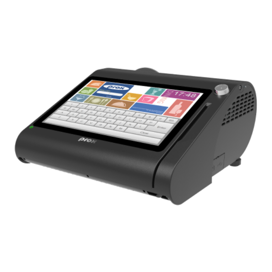
- Page 1 USER MANUAL PA-A310 10.1” POS Terminal Powered by Intel Celeron ® ® J3355 / 3455 CPU PA-A310 M1...
- Page 2 10.1” Fanless POS Terminal ® ® with Intel Celeron J3355 / 3455 CPU COPYRIGHT NOTICE & TRADEMARK All trademarks and registered trademarks mentioned herein are the property of their respective owners. This manual is copyrighted in Oct. 2019. You may not reproduce or transmit in any form or by any means, electronic, or mechanical, including photocopying and recording.
- Page 3 CE NOTICE This is a class A product. In a domestic environment this product may cause radio interference in which case the user may be required to take adequate measures. FCC NOTICE This equipment has been tested and found to comply with the limits for a Class A digital device, pursuant to part 15 of the FCC Rules.
-
Page 4: Table Of Contents
Contents Revision History ................... viii Introduction ..................1-1 About This Manual ..............1-2 Getting Started ..................2-1 Package List ................2-2 System Views Without i-Button and Fingerprint Modules ..2-3 2.2.1 Front View ................. 2-3 2.2.2 Rear View ................2-3 2.2.3 Top View ................ - Page 5 System Specifications ............. 2-14 Safety Precautions ..............2-16 System Configuration ................. 3-1 External System I/O Ports Diagram & Pin Assignment ..... 3-2 3.1.1 Rear I/O Ports Diagram ............. 3-2 Jumper & Connector Quick Reference Table ......3-4 Component Locations Of System Main Board ......3-6 3.3.1 Top View of System Main Board ........
- Page 6 3.6.6 USB 2.0 Connectors (USB2, USB5, USB6, JUSB7) ..3-27 3.6.7 HD Audio Connector (JAUD1) ......... 3-28 3.6.8 LVDS Inverter Connector (JINV1) ........3-29 3.6.9 LVDS Connector (LVDS1) ..........3-30 3.6.10 M.2 Wi-Fi Express Slot (M2_E) ........3-31 3.6.11 M.2 SSD Express Slot (M2_M) ........3-32 3.6.12 SATA 3.0 &...
- Page 7 3.7.2.1 Power Supply Connector ..........3-52 3.7.2.2 RS-232 Interface Connector ........3-52 3.7.2.3 Thermal Head/Motor/Sensor Connector ...... 3-53 3.7.2.4 Auto-Cutter Connector ..........3-55 3.7.2.5 Paper-Near-END Sensor Connector ......3-55 3.7.2.6 USB Interface Connector ..........3-56 3.7.2.7 Terminal Assignment Connector ........3-56 3.7.3 Printer Board: MB-1011 &...
- Page 8 3.9.2.1 Information Button Reader ........... 3-68 3.9.2.2 Output Connector ............3-68 Software Utilities ................. 4-1 Introduction ................4-2 ® Installing Intel Chipset Software Installation Utility ....4-3 ® 4.2.1 Installing Intel Chipset Driver ........... 4-3 Installing Graphics Driver Utility ..........4-4 ®...
- Page 9 4.10.4.3 OPOS MSR Tester ............. 4-85 4.11 API ................... 4-89 4.11.1 API Package Content ............4-89 4.11.2 API Procedure ..............4-90 4.11.3 Cash Drawer ..............4-93 4.11.4 Watchdog ................. 4-94 4.12 API Function ................4-95 4.12.1 Cash Drawer Function ............. 4-95 4.12.2 Watch Dog Function ............
- Page 10 5.5.2 South Cluster Configuration ..........5-32 Security ................... 5-40 Boot ..................5-42 Save & Exit ................5-43 Appendix A System Diagrams ............ A-1 Exploded Diagram For System Top Case ..........A-2 System Exploded Diagram ...............A-3 System LCD Panel Assembly Exploded Diagram ........A-5 MSR Module Assembly Exploded Diagram ..........A-7 HDD Module Assembly Exploded Diagram ..........A-8 Power USB Module Assembly Exploded Diagram ........A-9...
-
Page 11: Revision History
Revision History The revision history of PA-A310 User Manual is described below: Version No. Revision History Page No. Date Initial Release 2019/10/02 viii... -
Page 12: Introduction
Introduction This chapter provides the introduction for the PA-A310 system as well as the framework of the user manual. The following topic is included: • About This Manual Page: 1-1 PA-A310 SERIES USER MANUAL... -
Page 13: About This Manual
Chapter 1 Introduction 1.1 About This Manual Thank you for purchasing our PA-A310 system. The PA-A310 is an updated system designed to be comparable with the highest performance of IBM AT personal computers. The PA-A310 provides faster processing speed, greater expandability and can handle more tasks than before. -
Page 14: Getting Started
Getting Started This chapter provides the information for the PA-A310 system. It describes how to set up the system quickly and outlines the system specifications. The following topics are included: • Package List • System Overview • System Diagrams • System Specification •... -
Page 15: Package List
Q’ty PA-A310 Manual / Driver DVD Quick Reference Guide AC Power Cord (Optional) MSR Card Reader (Optional) i-Button + MSR Card Reader (Optional) Barcode Scanner (Optional) Wireless LAN (IEEE 802.11 b+g) (Optional) VFD (Optional) Page: 2-2 PA-A310 SERIES USER MANUAL... -
Page 16: System Views Without I-Button And Fingerprint Modules
Chapter 2 Getting Started 2.2 System Views Without i-Button and Fingerprint Modules 2.2.1 Front View Unit: mm Without i-Button Without Fingerprint 2.2.2 Rear View COM2 COM3 HDMI LAN USB1/2 USB3/4 DC IN COM1 Page: 2-3 PA-A310 SERIES USER MANUAL... -
Page 17: Top View
Chapter 2 Getting Started 2.2.3 Top View Without i-Button 298.29 Without i-Button Page: 2-4 PA-A310 SERIES USER MANUAL... -
Page 18: Bottom View
Chapter 2 Getting Started 2.2.4 Bottom View 2.2.5 Quarter View Without i-Button Page: 2-5 PA-A310 SERIES USER MANUAL... -
Page 19: Side View
Chapter 2 Getting Started 2.2.6 Side View Unit: mm Without Fingerprint module Without Fingerprint Page: 2-6 PA-A310 SERIES USER MANUAL... -
Page 20: Front View
Chapter 2 Getting Started 2.3 System Views With i-Button Module 2.3.1 Front View With i-Button 2.3.2 Rear View COM2 COM3 HDMI LAN USB1/2 USB3/4 DC IN COM1 Page: 2-7 PA-A310 SERIES USER MANUAL... -
Page 21: Top View
Chapter 2 Getting Started Top View 2.3.3 With i-Button 298.29 With i-Button Page: 2-8 PA-A310 SERIES USER MANUAL... -
Page 22: Bottom View
Chapter 2 Getting Started 2.3.4 Bottom View 2.3.5 Quarter View With i-Button Page: 2-9 PA-A310 SERIES USER MANUAL... -
Page 23: Side View
Chapter 2 Getting Started 2.3.6 Side View Page: 2-10 PA-A310 SERIES USER MANUAL... -
Page 24: Front View
Chapter 2 Getting Started 2.4 System Views With Fingerprint Module 2.4.1 Front View 2.4.2 Rear View COM2 COM3 HDMI LAN USB1/2 USB3/4 DC IN COM1 Page: 2-11 PA-A310 SERIES USER MANUAL... -
Page 25: Top View
Chapter 2 Getting Started 2.4.3 Top View 298.29 Page: 2-12 PA-A310 SERIES USER MANUAL... -
Page 26: Bottom View
Chapter 2 Getting Started 2.4.4 Bottom View 2.4.5 Side View With Fingerprint Page: 2-13 PA-A310 SERIES USER MANUAL... -
Page 27: System Specifications
Customer Display dots 2" or 3" easy loading thermal printer with auto-cutter Printer JIS-I or II, ISO Track1+2+3 (PS/2 interface) MSR & i-Button 8-bit grayscale reader Fingerprint Display 10.1" TFT LCD Page: 2-14 PA-A310 SERIES USER MANUAL... - Page 28 24 ~ 30 degrees Tilt Angle Environment CE / FCC EMC & Safety 0°C ~ 35°C (32°F ~ 95°F) Operating Temp. -5°C ~ 60°C (23°F ~ 140°F) Storage Temp. 20% ~ 90% Humidity Page: 2-15 PA-A310 SERIES USER MANUAL...
-
Page 29: Safety Precautions
Avoid direct sunlight exposure for a long period of time (for example, in a closed car in summer time. Also avoid the system from any heating device.). Or do not use PA-A310 when it has been left outdoors in a cold winter day. •... -
Page 30: System Configuration
• Setting Main Board Connectors and Jumpers • Printer Board Component Locations & Pin Assignment • Setting Printer Board Connectors and Jumpers MB-1030 series MB-1011 & MB-1013 • Setting VFD Board Connectors and Jumpers • Setting MSR Page: 3-1 PA-A310 SERIES USER MANUAL... -
Page 31: External System I/O Ports Diagram & Pin Assignment
(Option) (Option) (Option) (Option) DWR2 LINE COM4 HDMI DC IN COM1 COM2 USB 1/2 USB 3/4 COM3 DC IN COM2 HDMI USB 3.0 COM1 COM3 USB 2.0 DRW1 extended with Y cable DRW1-1 DRW1-2 Page: 3-2 PA-A310 SERIES USER MANUAL... - Page 32 LINE COM4 HDMI DC IN COM2 COM1 COM3 USB 1/2 USB 3/4 DC IN COM2 HDMI USB 3.0 COM1 COM3 USB 2.0 DRW1 extended with Y cable DRW1-1 DRW1-2 Side I/O Power USB7 Button Page: 3-3 PA-A310 SERIES USER MANUAL...
-
Page 33: Jumper & Connector Quick Reference Table
Dual USB 2.0 Ports (rear I/O) USB3_1 USB 2.0 Port (side I/O) USB7 COM Connectors COM1_1, COM2_1, COM4 VGA Connector JVGA1 USB3_2, USB2, USB5, USB6, USB 2.0 Connectors JUSB7 HD Audio Connector JAUD1 LVDS Inverter Connector JINV1 Page: 3-4 PA-A310 SERIES USER MANUAL... - Page 34 SATA 3.0 & SATA Power Connectors SATA1, SATA_PWR1 LPC Connector JLPC1 Fan Connector FAN_1 OUT_5V, OUT12V_1, OUT12V_2, Power Output Connectors OUT_24V RTC Connector BAT1 PS/2 (MSR) Connector Speaker Connector JSPK1 Switch LED Connectors SW2, LED1 Page: 3-5 PA-A310 SERIES USER MANUAL...
-
Page 35: Component Locations Of System Main Board
COM4 OUT12V_1 I-BUT1 JP_USB5 JP_USB3_2 JINV1 USB3_2 LVDS1 JP_VDD1 JP_USB3_1 USB5 FAN_1 JUSB7 M.2 SSD EDP1 PS2 M.2 Wi-Fi M2_M M2_E USB2 LED1 JSPK1 BAT1 JAUD1 Figure 3-1 Main Board Component Location (Top View) Page: 3-6 PA-A310 SERIES USER MANUAL... - Page 36 CAUTION: Always touch the motherboard components by the edges. Never touch components such as a processor by its pins. Take special cares while you are holding electronic circuit boards by the edges only. Do not touch the main board components. Page: 3-7 PA-A310 SERIES USER MANUAL...
-
Page 37: Bottom View Of System Main Board
Chapter 3 System Configuration 3.3.2 Bottom View of System Main Board Page: 3-8 PA-A310 SERIES USER MANUAL... -
Page 38: How To Set Jumpers
2 to create one setting and shorting. You can also select to connect pins 2 and 3 to create another setting. The format of the jumper picture will be illustrated throughout this manual. The figure below shows different types of jumpers and jumper settings. Page: 3-9 PA-A310 SERIES USER MANUAL... - Page 39 Chapter 3 System Configuration Jumper diagrams Jumper settings Page: 3-10 PA-A310 SERIES USER MANUAL...
-
Page 40: Function Buttons And I/O Ports
To turn on the system, press the power button on the Power side of the system briefly. Button ACTION ASSIGNMENT Press Release +3.3V 3.5.2 DC_IN Port (DC_IN1) Port Name: DC_IN1 Description: DC Power-In Port (rear I/O) PIN ASSIGNMENT PIN ASSIGNMENT VIN_24V VIN_24V DC_IN1 Page: 3-11 PA-A310 SERIES USER MANUAL... -
Page 41: Com Ports (Com1, Com2, Com3, Com4)
COM1/2/3_DCD COM1/2/3_RX COM1/2/3_TX COM1/2/3_DTR COM1/ COM1/2/3_DSR COM1/2/3_RTS COM2/ COM1/2/3_CTS COM3/ COM1/2/3_RI_SEL Port Name: COM4 (optional) Description: D-Sub9 Serial Port (rear I/O) ASSIGNMENT PIN ASSIGNMENT COM4_DCD COM4_DSR COM4_RX COM4_RTS COM4_TX COM4_CTS COM4/ COM4_DTR COM4_RI_SEL (optional) Page: 3-12 PA-A310 SERIES USER MANUAL... -
Page 42: Hdmi Port (Hdmi1) And Vga Port (Vga, Optional)
DP0_HDMI_N1 DP0_HDMI_P0 DP0_HDMI_N0 DP0_HDMI_CLKP DP0_HDMI_CLKN DP0_HDMI_SCL_5V DP0_HDMI_SDA_5V VCC5_HDMI DP1_HDMI_HPD_IN VGA Port (optional) Port Name: VGA Description: VGA Port, D-Sub 15-pin (rear I/O) PIN ASSIGNMENT PIN ASSIGNMENT GREEN BLUE DDCA DATA HSYNC VSYNC DDCA CLK Page: 3-13 PA-A310 SERIES USER MANUAL... -
Page 43: Lan Port (Lan1)
Ethernet connection. LAN LED Color Status Description Indicator Right Side Orange Blink Giga LAN connection is activated. Green Blink 10/100Mbps LAN connection is activated. Left Side Yellow LAN switch/hub connected. Page: 3-14 PA-A310 SERIES USER MANUAL... -
Page 44: Dual Usb 3.0 Ports (Usb1)
USB 3.0 signals: ASSIGNMENT ASSIGNMENT USB3_RXN0 USB3_RXP0 USB2_P0_DP USB3_TXN0 USB2_P0_DN USB3_TXP0 VCC5_USB1 USB3_RXN1 USB1 USB3_RXP1 USB2_P1_DP USB3_TXN1 USB2_P1_DN USB3_TXP1 VCC5_USB1 Note: USB1 is provided with standby power 5V. The other USB ports are without standby power. Page: 3-15 PA-A310 SERIES USER MANUAL... -
Page 45: Dual Usb 2.0 Ports (Usb3_1)
Description: Dual USB 2.0 Connectors (Type A) (Rear I/O) USB 2.0 signals: ASSIGNMENT ASSIGNMENT VCC5_USB3 VCC5_USB3 USB2_P3_DN USB2_P4_DN USB2_P3_DP USB2_P4_DP USB3_1 3.5.8 USB 2.0 Port (USB7) Port Name: USB7 Description: USB 2.0 Port (side I/O) ASSIGNMENT VCC5_USB7 USB2_P7_DN USB2_P7_DP USB7 Page: 3-16 PA-A310 SERIES USER MANUAL... -
Page 46: Cash Drawer Port (Dwr1)
Chapter 3 System Configuration 3.5.9 Cash Drawer Port (DWR1) Port Name: DWR1 Description: DWR1 is used by default. ASSIGNMENT GND/OPEN2 OPEN1 SENSE1 12V/24V DWR1 NC/SENSE2 Page: 3-17 PA-A310 SERIES USER MANUAL... -
Page 47: Setting Main Board Connectors And Jumpers
COM4_RX COM4_RTS COM4 COM4_TX COM4_CTS COM4_DTR COM4_RI Note: COM4 will not function when jumpers JP6, JP7, JP8 are set as 2-3 connected (i-Button). Refer to the COM4 & i-Button Function Selection section for details. Page: 3-18 PA-A310 SERIES USER MANUAL... -
Page 48: Vga Connector (Jvga1)
Chapter 3 System Configuration 3.6.2 VGA Connector (JVGA1) Connector Location: JVGA1 Description: VGA Connector ASSIGNMENT ASSIGNMENT CRT_RED_LL CRT_GREEN_LL CRT_BLUE_LL SPC_R CRT_VCC_L SPD_R CRT_DDC_DATA_O CRT_HSYNC_O CRT_VSYNC_O CRT_DDC_CLK_O JVGA1 Page: 3-19 PA-A310 SERIES USER MANUAL... -
Page 49: Com4 & I-Button Function Selection (Jp6, Jp7, Jp8)
JUMPER ILLUSTRATION COM4 JP6/JP7/JP8 (Default Setting) I-BUT JP6/JP7/JP8 Note: COM4 will not function when jumpers JP6, JP7, JP8 are set as 2-3 connected (i-Button). Refer to the COM4 & i-Button Function Selection section for details. Page: 3-20 PA-A310 SERIES USER MANUAL... -
Page 50: Cash Drawer Control Selection (Jp11)
DRW1-1 & DRW1-2 using the Y-Cable (option). Jumper Location: JP11 Description: Cash Drawer Selection Selection Jumper Setting Jumper Illustration 1 Drawer & 3-5, 4-6 (Default Setting) JP11 1 Drawer & 2-4, 3-5 JP11 2 Drawers & 1-3, 4-6 JP11 Page: 3-21 PA-A310 SERIES USER MANUAL... - Page 51 Y cable DRW1-1 DRW1-2 Step 3. DRW1, DRW1-1, DRW1-2 shares the same power source. (Default: 12V). SIO Address Cash drawer 1 LDN 06, 0x91 bit 2 Cash drawer 2 LDN 06, 0x91 bit 3 Page: 3-22 PA-A310 SERIES USER MANUAL...
- Page 52 To exit the Extended Function Mode, writing 0xAA to the EFER is required. Once the chip exits the Extended Function Mode, it is in the normal running mode and is ready to enter the configuration mode. Page: 3-23 PA-A310 SERIES USER MANUAL...
- Page 53 Note: The DWR2 Port can function only when the optional "Printer Kit" is installed on PA-A310. The DWR2 signals from the printer board (MB-1030, MB-1011, MB-1013) can be controlled via relevant commands. See the picture below for the location of...
- Page 54 Chapter 3 System Configuration ASSIGNMENT Drawer Open Drawer Sense +24V DWR2 Hexadecimal Control Codes Function Codes <DLE EOT> 10 04 Real-time status transmission <DLE DC4> 10 14 Real-time output of the specified pulse Page: 3-25 PA-A310 SERIES USER MANUAL...
- Page 55 Chapter 3 System Configuration 3.6.5 USB 2.0 Connector (USB3_2) Connector Location: USB3_2 Description: USB 2.0 Connector ASSIGNMENT ASSIGNMENT VCC5_USB3 VCC5_USB3 USB2_P3_DN USB2_P4_DN USB2_P3_DP USB2_P4_DP USB3_2 Page: 3-26 PA-A310 SERIES USER MANUAL...
-
Page 56: Usb 2.0 Connectors (Usb2, Usb5, Usb6, Jusb7)
USB2/ Description: USB 2.0 Connector ASSIGNMENT USB5/ VCC5_USB5 USB2_P5_DN USB6 USB2_P5_DP Connector Location: USB6 Description: USB 2.0 Connector ASSIGNMENT VCC5_USB5 USB2_P6_DN USB2_P6_DP Connector Location: JUSB7 Description: USB 2.0 Connector ASSIGNMENT VCC5_USB7 USB2_P7_DN USB2_P7_DP JUSB7 Page: 3-27 PA-A310 SERIES USER MANUAL... -
Page 57: Hd Audio Connector (Jaud1)
Chapter 3 System Configuration 3.6.7 HD Audio Connector (JAUD1) Connector Location: JAUD1 Description: HD Audio Connector ASSIGNMENT ASSIGNMENT HD_MIC-L HD_GND HD_MIC-R PRESENCE_N JAUD1 LINE-OUT-R MIC-JD HD_GND LINE-OUT-L LINE-OUT-JD Page: 3-28 PA-A310 SERIES USER MANUAL... -
Page 58: Lvds Inverter Connector (Jinv1)
Chapter 3 System Configuration 3.6.8 LVDS Inverter Connector (JINV1) Connector Location: JINV1 Description: LVDS Inverter Connector ASSIGNMENT V12P0_INV V12P0_INV JINV1 LVDS_BKLCTL LVDS_BKLTEN Page: 3-29 PA-A310 SERIES USER MANUAL... -
Page 59: Lvds Connector (Lvds1)
LVDS Connector (LVDS1) Connector Location: LVDS1 Description: LVDS Connector LVDS1 ASSIGNMENT ASSIGNMENT LVDS_VCC LVDS_CLKB_DN LVDS_CLKB_DP LVDS_B2_DN LVDS_B2_DP LVDS_B1_DN LVDS_B1_DP LVDS_B3_DP LVDS_B3_DN LVDS_B0_DP LVDS_B0_DN LVDS_CLKA_DP LVDS_CLKA_DN LVDS_A2_DP LVDS_A2_DN LVDS_A1_DP LVDS_A1_DN LVDS_A0_DP LVDS_A0_DN LVDS_A3_DP LVDS_A3_DN LVDS_VCC LVDS_VCC Page: 3-30 PA-A310 SERIES USER MANUAL... - Page 60 M.2 Wi-Fi Express Slot (M2_E) Connector Location: M2_E Description: M.2 Wi-Fi Express Slot ASSIGNMENT ASSIGNMENT V3P3S USB2_P2_DP V3P3S USB2_P2_DN M2_E PCIE_P1_TXP PCIE_P1_TXN PCIE_P1_RXP PCIE_P1_RXN M2_PCIE_CLKP M2_PCIE_CLKN SUSCLK WIFI_RST_ M2_PCIE_CLKREQ KILL_BT_N WAKE_M2_PCIE_N KILL_WIFI_N V3P3S V3P3S Page: 3-31 PA-A310 SERIES USER MANUAL...
-
Page 61: Ssd Express Slot (M2_M)
Chapter 3 System Configuration 3.6.11 M.2 SSD Express Slot (M2_M) Connector Location: M2_M Description: M.2 SSD KEY M Slot ASSIGNMENT ASSIGNMENT V3P3S V3P3S M2_M SATA_DEVSLP1 SATA_RXP1 SATA_RXN1 SATA_TXN1 SATA_TXP1 V3P3S V3P3S V3P3S Page: 3-32 PA-A310 SERIES USER MANUAL... - Page 62 Chapter 3 System Configuration SATA 3.0 & SATA Power Connectors (SATA1, SATA_PWR1) 3.6.12 Connector Location: SATA1 Description: Serial ATA 3.0 connector ASSIGNMENT SATA_TXP0 SATA_TXN0 SATA_RXN0 SATA_RXP0 SATA1 Connector Location: SATA_PWR1 Description: HDD Power Connector ASSIGNMENT VCC5 SATA_PWR1 Page: 3-33 PA-A310 SERIES USER MANUAL...
-
Page 63: Lpc Connector (Jlpc1)
Connector Location: JLPC1 Description: Low Pin Count Connector ASSIGNMENT ASSIGNMENT LPC_CLKOUT1 LPC_LFRAMEJ JLPC1 PMU_PLTRST_N LPC_AD0 LPC_AD3 LPC_AD2 V3P3A LPC_AD1 3.6.14 Fan Connector (FAN_1) Connector Location: FAN_1 Description: Fan Connector ASSIGNMENT FAN_1 V12P0S FANIN FANOUT Page: 3-34 PA-A310 SERIES USER MANUAL... -
Page 64: Power Output Connectors
Connector Location: OUT12V_1 Description: Output 12V Wafer ASSIGNMENT V12P0S V12P0S OUT12V_1 Connector Location: OUT12V_2 Description: Output 12V Wafer ASSIGNMENT V12P0S V12P0S OUT12V_2 / Connector Location: OUT24V OUT24V Description: Output 24V Wafer ASSIGNMENT VIN_24V VIN_24V Page: 3-35 PA-A310 SERIES USER MANUAL... -
Page 65: Rtc Connector (Bat1)
Chapter 3 System Configuration 3.6.16 RTC Connector (BAT1) Connector Location: BAT1 Description: RTC Connector ASSIGNMENT VBAT BAT1 3.6.17 PS/2 (MSR) Connector (PS2) Connector Location: PS2 Description: PS/2 (MSR) Connector ASSIGNMENT KB_CLK KB_DATA KBMS_VCC Page: 3-36 PA-A310 SERIES USER MANUAL... -
Page 66: Speaker Connector (Jspk1)
Chapter 3 System Configuration 3.6.18 Speaker Connector (JSPK1) Connector Location: JSPK1 Description: Speaker Connector ASSIGNMENT HD_SPK_R HD_SPK_L JSPK1 Page: 3-37 PA-A310 SERIES USER MANUAL... -
Page 67: Switch Led Connectors (Sw2, Led1)
Chapter 3 System Configuration 3.6.19 Switch LED Connectors (SW2, LED1) Connector Location: SW2 Description: Power Button ASSIGNMENT PWRBTNJ Connector Location: LED1 Description: System Power LED ASSIGNMENT V5P0S LED1 Page: 3-38 PA-A310 SERIES USER MANUAL... - Page 68 Chapter 3 System Configuration 3.6.20 USB2 Port Selection (JP_USB2) Jumper Location: JP_USB2 Description: USB2 Port Selection Selection Jumper Setting Jumper Illustration M.2 USB 1-3, 2-4 JP_USB2 3-5, 4-6 USB2 (Default Setting) JP_USB2 Page: 3-39 PA-A310 SERIES USER MANUAL...
- Page 69 Chapter 3 System Configuration 3.6.21 USB3 Port Selection (JP_USB3_1, JP_USB3_2) Jumper Location: JP_USB3_1, JP_USB3_2 Description: USB3 Port Selection Selection Jumper Setting Jumper Illustration 1-3, 2-4 USB3_1 (Default Setting) JP_USB3_1/ JP_USB3_2 USB3_2 3-5, 4-6 JP_USB3_1/ JP_USB3_2 Page: 3-40 PA-A310 SERIES USER MANUAL...
-
Page 70: Usb5 Port Selection (Jp_Usb5)
Chapter 3 System Configuration 3.6.22 USB5 Port Selection (JP_USB5) Jumper Location: JP_USB5 Description: USB5 Port Selection Selection Jumper Setting Jumper Illustration 3-5, 4-6 USB5 (Default Setting) JP_USB5 Page: 3-41 PA-A310 SERIES USER MANUAL... -
Page 71: Force Dnx Firmware Load Selection (Jp1)
Selection Jumper Setting Jumper Illustration Open Normal (Default Setting) Force 3.6.24 Flash Descriptor Override Selection (JP1) Jumper Location: JP1 Description: Flash Descriptor Override Selection Selection Jumper Setting Jumper Illustration Open Normal (Default Setting) Override Page: 3-42 PA-A310 SERIES USER MANUAL... -
Page 72: Lvds Sequence Control Selection (Jp4)
Chapter 3 System Configuration LVDS Sequence Control Selection (JP4) 3.6.25 Jumper Location: JP4 Description: LVDS Sequence Control Selection Selection Jumper Setting Jumper Illustration 1-3, 2-4 From CPU (Default Setting) From CH7511 3-5, 4-6 Page: 3-43 PA-A310 SERIES USER MANUAL... -
Page 73: Lvds Backlight Enable Voltage Selection (Jp5)
Chapter 3 System Configuration 3.6.26 LVDS Backlight Enable Voltage Selection (JP5) Jumper Location: JP5 Description: LVDS Backlight Enable Voltage Selection Selection Jumper Setting Jumper Illustration 3.3V (Default Setting) Page: 3-44 PA-A310 SERIES USER MANUAL... -
Page 74: Lvds Voltage Selection (Jp_Vdd1)
Chapter 3 System Configuration 3.6.27 LVDS Voltage Selection (JP_VDD1) Jumper Location: JP_VDD1 Description: LVDS Voltage Selection Selection Jumper Setting Jumper Illustration 3.3V (Default Setting) JP_VDD1 JP_VDD1 Page: 3-45 PA-A310 SERIES USER MANUAL... -
Page 75: Slide Switch For Lvds Resolution Selection (Sw1)
Connector Location: SW1 Description: Slide Switch for LVDS Resolution/Channel/Color Bit Selection SELECTION SETTING 1200 x 800 1CH/24bit (Default Setting) 1024 x 600 1CH/24bit 1024 x 768 1CH/18bit 1024 x 768 1CH/24bit 1280 x 768 1CH/18bit Page: 3-46 PA-A310 SERIES USER MANUAL... - Page 76 Chapter 3 System Configuration SELECTION SETTING 1280 x 960 1CH/24bit 1280 x 1024 2CH/24bit 1366 x 768 1CH/18bit 1366 x 768 1CH/24bit 1440 x 900 2CH/24bit Page: 3-47 PA-A310 SERIES USER MANUAL...
- Page 77 Chapter 3 System Configuration SELECTION SETTING 1400 x 1050 2CH/24bit 1600 x 900 2CH/24bit 1680 x 1050 2CH/24bit 1600 x 1200 2CH/24bit 1920 x 1080 2CH/24bit Page: 3-48 PA-A310 SERIES USER MANUAL...
-
Page 78: Clear Cmos Data Selection (Jp3)
Step 4. Power on the PC and the PC will then auto-reboot for once in order to set SoC’s register. Step 5. Done! SELECTION JUMPER SETTING JUMPER ILLUSTRATION Open Normal (Default Setting) Clear CMOS* Note: Please make sure the main power is off before you clear CMOS data. Page: 3-49 PA-A310 SERIES USER MANUAL... -
Page 79: Printer Board Component Locations & Pin Assignment
Chapter 3 System Configuration 3.7 Printer Board Component Locations & Pin Assignment 3.7.1 Printer Board: MB-1030 series CUT_CN1 COM1 9 10 USB_CN1 24V_CN1 PRINT_CN1 Figure 3-2. MB-1030 Printer Board Component Locations Page: 3-50 PA-A310 SERIES USER MANUAL... -
Page 80: Jumper & Connector Quick Reference Table
Jumper & Connector Quick Reference Table Jumper / Connector NAME Power Supply Connector 24V_CN1 RS-232 Interface Connector COM1 Thermal Head/Motor/Sensor Connector PRINT_CN1 Auto-Cutter Connector CUT_CN1 Paper-Near-END Sensor Connector USB Interface Connector USB_CN1 Terminal Assignment Connector Page: 3-51 PA-A310 SERIES USER MANUAL... -
Page 81: Setting Printer Board Connectors And Jumpers
Setting Printer Board Connectors and Jumpers 3.7.2.1 Power Supply Connector 24V_CN1: Power Supply Wafer ASSIGNMENT +24V +24V 24V_CN1 3.7.2.2 RS-232 Interface Connector COM1: RS-232 Interface Connector ASSIGNMENT ASSIGNMENT DSR /CTS DTR /RTS 9 10 COM1 Page: 3-52 PA-A310 SERIES USER MANUAL... -
Page 82: Thermal Head/Motor/Sensor Connector
Head strobe signal DST1 Head strobe signal Head GND Head GND Head GND Head GND Head GND Head GND LATCH Print data latch Head drive power Head drive power Head drive power Head drive power Page: 3-53 PA-A310 SERIES USER MANUAL... - Page 83 Power supply of the out-of-paper sensor GND of the platen position/ out-of-paper sensor Signal of the platen position sensor Unused Frame GND Frame GND Unused Motor drive signal Motor drive signal Motor drive signal Motor drive signal Page: 3-54 PA-A310 SERIES USER MANUAL...
-
Page 84: Auto-Cutter Connector
1A-2 Auto-cutter motor drive signal 3.7.2.5 Paper-Near-END Sensor Connector CN2: Paper-near-end sensor connector ASSIGNMENT FUNCTION Power supply of the near end sensor Signal of the near end sensor GND of the near end sensor Page: 3-55 PA-A310 SERIES USER MANUAL... -
Page 85: Usb Interface Connector
Feed signal RESET Reset signal Status signal Status signal Status signal Status signal Drawer sensor signal Drawer switch signal Drive terminal for the drawer (Vp side) GNDdu Drive terminal for the drawer (GND side) Unused Page: 3-56 PA-A310 SERIES USER MANUAL... -
Page 86: Printer Board: Mb-1011 & Mb-1013
Chapter 3 System Configuration 3.7.3 Printer Board: MB-1011 & MB-1013 MB-1013 MB-1011 Figure 3-3. MB-1011 & MB-1013 Printer Board Component Locations Page: 3-57 PA-A310 SERIES USER MANUAL... -
Page 87: Jumper & Connector Quick Reference Table
Chapter 3 System Configuration 3.7.3.1 Jumper & Connector Quick Reference Table Jumper / Connector NAME Power Supply Connector RS-232 Interface Connector Auto-Cutter Connector Thermal Head/Motor/Sensor Connector Terminal Assignment Connector USB Interface Connector Page: 3-58 PA-A310 SERIES USER MANUAL... -
Page 88: Setting Printer Board Connectors And Jumpers: Mb-1011
Chapter 3 System Configuration 3.7.4 Setting Printer Board Connectors and Jumpers: MB-1011 & MB-1013 3.7.4.1 Power Supply Connector CN1: Power supply wafer ASSIGNMENT +24V +24V 3.7.4.2 RS-232 Interface Connector CN7: RS-232 interface connector ASSIGNMENT ASSIGNMENT Page: 3-59 PA-A310 SERIES USER MANUAL... -
Page 89: Auto-Cutter Connector
Head drive power Head drive power Head drive power Head drive power Head drive power Print data output Synchronizing signal for print data transfer Head GND Head GND Head GND Head GND Head GND Head GND Page: 3-60 PA-A310 SERIES USER MANUAL... - Page 90 Power supply of the out-of-paper sensor GND of the platen position/ out-of-paper sensor Signal of the platen position sensor Unused Frame GND Frame GND Unused Motor drive signal Motor drive signal Motor drive signal Motor drive signal Page: 3-61 PA-A310 SERIES USER MANUAL...
-
Page 91: Terminal Assignment Connector
Status signal Drawer sensor signal Drawer switch signal Drive terminal for the drawer (Vp side) GNDdu Drive terminal for the drawer (GND side) Unused 3.7.4.6 USB Interface Connector CN8: USB interface connector ASSIGNMENT Vbus Page: 3-62 PA-A310 SERIES USER MANUAL... -
Page 92: Vfd Board Component Locations & Pin Assignment
Chapter 3 System Configuration 3.8 VFD Board Component Locations & Pin Assignment 3.8.1 VFD Board: MB-4103, LD720 JP12V Figure 3-4. MB-4103 & LD720 VFD Board Component Locations Page: 3-63 PA-A310 SERIES USER MANUAL... -
Page 93: Jumper & Connector Quick Reference Table
Chapter 3 System Configuration 3.8.2 Jumper & Connector Quick Reference Table Jumper / Connector NAME Power Switch Selection JP12V RS-232 Serial Interface Connector Page: 3-64 PA-A310 SERIES USER MANUAL... - Page 94 Chapter 3 System Configuration 3.8.3 Setting MB-4103 & LD720 VFD Board Connectors and Jumpers 3.8.3.1 Power Switch Selection JP12V: Power Switch Selection SELECTION JUMPER SETTING JUMPER ILLUSTRATION JP12V (Default) JP12V Page: 3-65 PA-A310 SERIES USER MANUAL...
- Page 95 Chapter 3 System Configuration 3.8.3.2 RS-232 Serial Interface Connector CN1: RS-232 serial interface wafer ASSIGNMENT ASSIGNMENT +12V/+5V Page: 3-66 PA-A310 SERIES USER MANUAL...
-
Page 96: Msr Board Component Locations & Pin Assignment
3.9 MSR Board Component Locations & Pin Assignment 3.9.1 ID TECH ID-TECH MSR Board Component Locations 3.9.1.1 Main Connector ASSIGNMENT ASSIGNMENT K-CLK Chassis Ground (Computer connections) P-CLK K-DATA (Keyboard connections) (Computer connections) P-DATA (Keyboard connections) +5V Vcc Page: 3-67 PA-A310 SERIES USER MANUAL... -
Page 97: Information Button Reader
MB-3012 MSR Board Component Locations 3.9.2.1 Information Button Reader I_BUTTON1: Information button reader ASSIGNMENT I_B1 I_BUTTON1 3.9.2.2 Output Connector IO1: Output wafer ASSIGNMENT ASSIGNMENT CLK_KB RX_MSR CLK_PC TX_MSR DATA_KB DATA_PC USB_D+_R USB_D-_R CHASSIS GND Page: 3-68 PA-A310 SERIES USER MANUAL... -
Page 98: Software Utilities
• Installing Sound Driver Utility • Installing Microsoft Hotfix kb3211320 and kb3213986 Driver Utility • Installing Serial I/O Driver Utility • Installing Windows 10 I/O Driver Utility • Peripheral Devices - Printer - VFD - MSR • API PA-A310 SERIES USER MANUAL Page: 4-1... - Page 99 Chapter 4 Software Utilities 4.1 Introduction Enclosed with the PA-A310 Series package is our driver utilities contained in a DVD-ROM disk. Refer to the following table for driver locations: Filename (Assume that Purpose Win10 DVD- ROM drive is D :)
-
Page 100: Installing Intel
10 series, and it should be installed right after the OS installation. Please follow the steps below: Connect the USB DVD-ROM device to PA-A310 and insert the driver disk. Enter the “Main Chip” folder where the Chipset driver is located. -
Page 101: Installing Graphics Driver Utility
Chapter 4 Software Utilities 4.3 Installing Graphics Driver Utility To install the Graphics driver, follow the steps below: Connect the USB DVD-ROM device to PA-A310 and insert the driver disk. Enter the “Graphics” folder where the Graphics driver is located. -
Page 102: Installing Intel Trusted Execution Engine Installation Utility
® 4.4 Installing Intel Trusted Execution Engine Installation Utility Connect the USB DVD-ROM device to PA-A310 and insert the driver disk. Enter the TXE folder where the driver is located. Click SetupTXE.exe file for TXE driver installation. Follow the on-screen instructions to complete the installation. -
Page 103: Installing Sound Driver Utility
® Windows 10 series. To install the Sound Driver, follow the steps below: Connect the USB DVD-ROM device to PA-A310 and insert the driver disk. Enter the “Sound Codec” folder where the sound driver is located. Click Setup.exe file for driver installation. -
Page 104: Installing Microsoft Hotfix Kb3211320 And Kb3213986 Driver Utility
4.7 Installing Microsoft Hotfix kb3211320 and kb3213986 Driver Utility To install the Hotfix driver utility, follow the steps below: Connect the USB DVD-ROM device to PA-A310 and insert the driver disk. Enter the Hotfix folder where the driver is located. -
Page 105: Installing Windows 10 I/O Driver Utility
10 I/O Driver Utility ® To install the Windows I/O Driver, follow the steps below: Connect the USB DVD-ROM device to PA-A310 and insert the driver disk. Open the IO folder where the driver is located. Click the Intel_Processor_Win10_IO_Drivers_64Bit file for driver installation. -
Page 106: Peripheral Devices
GS h FS q GS k ESC 2 GS ! GS r ESC 3 GS $ GS v 0 ESC = GS * GS w ESC ? GS ( A ESC @ GS ( K PA-A310 SERIES USER MANUAL Page: 4-9... -
Page 107: Commands List
Print data in page mode Ignored <ESC SP> 1B 20 Set right-side character spacing <ESC !> 1B 21 Select print mode(s) <ESC $> 1B 24 Set absolute print position. <ESC *> 1B 2A Select bit image mode PA-A310 SERIES USER MANUAL Page: 4-10... - Page 108 1D 2A Define download bit images <GS ( A> 1D 28 41 Execute test print Disabled <GS ( K> 1D 28 4B Set print density Disabled ● <GS /> 1D 2F Print download bit image PA-A310 SERIES USER MANUAL Page: 4-11...
- Page 109 ● <GS k> 1D 6B Print bar code <GS r> 1D 72 Transmit status ● <GS v 0> 1D 76 30 Print raster bit image Disabled <GS w> 1D 77 Set bar code width PA-A310 SERIES USER MANUAL Page: 4-12...
- Page 110 ●: Enabled only when data is not present in the printer buffer. ▲: Only value setting is possible. Disabled: Parameters are processed as printable data. Ignored: All command codes including parameters are ignored and nothing is executed. PA-A310 SERIES USER MANUAL Page: 4-13...
- Page 111 After execution, makes the top of the line the next print starting position. [Name] Print and recover to standard mode (in page mode) ASCII [Format] Hex. Decimal 12 [Range] Prints all buffered data to the print region collectively, then recovers to the standard [Description] mode. PA-A310 SERIES USER MANUAL Page: 4-14...
- Page 112 Deletes all print data in the currently set print region in page mode. This command is enabled only in page mode. [Description] Portions included in the currently set print region are also deleted, even if previously set print region data. PA-A310 SERIES USER MANUAL Page: 4-15...
- Page 113 No error. Error occurs. Not used. Fixed to Off. n = 3 : Error status On / Off Decimal Function Not used. Fixed to Off. Not used. Fixed to On. Not used. Fixed to Off. PA-A310 SERIES USER MANUAL Page: 4-16...
- Page 114 = 1: Recover from the error and start printing from the line where the error [Description] occurred. n = 2: Recover from error after clearing the reception buffer and print buffer. This command is enabled even when the printer specification is disabled by ESC = (select peripheral devices). PA-A310 SERIES USER MANUAL Page: 4-17...
- Page 115 [Format] Hex. Decimal 0 ≤ n ≤ 255 [Range] Initial Value n = 0 This command sets the size of space to right of character. [Description] Right space = n × [horizontal motion units]. PA-A310 SERIES USER MANUAL Page: 4-18...
- Page 116 This command specifies the next print starting position in reference to the left edge of the print area. The printing start position is calculated using (nL + nH x [Description] 256) x (vertical or horizontal motion units). Specifications exceeding the print range are ignored. PA-A310 SERIES USER MANUAL Page: 4-19...
- Page 117 67 DPI 101 DPI nL+nH×256 density 8 dot double 67 DPI 203 DPI nL+nH×256 density 24 dot (nL+nH×256) 203 DPI 101 DPI single ×3 density 24 dot (nL+nH×256) double 203 DPI 203 DPI ×3 density PA-A310 SERIES USER MANUAL Page: 4-20...
- Page 118 Hex. Decimal 0 ≤ n ≤ 255 [Range] Initial Value n = 34 This command sets the line spacing using a following rule. [Description] Line spacing = n x (vertical or horizontal motion units) PA-A310 SERIES USER MANUAL Page: 4-21...
- Page 119 n specifies the column number for setting a horizontal tab position from the [Description] left margin or the beginning of the line. k indicates the number of horizontal tab positions to be set. PA-A310 SERIES USER MANUAL Page: 4-22...
- Page 120 In page mode, this command functions as follows, depending on the starting position of the printable area: (1) When the starting position is set to the upper left or lower right of the printable area using ESC T, the vertical motion unit (y) is used. PA-A310 SERIES USER MANUAL Page: 4-23...
- Page 121 FS q : Define NV bit image c. GS v 0 : Print raster bit images d. GS L : Set left margin Recover to standard mode using ESC @ (initialize printer). PA-A310 SERIES USER MANUAL Page: 4-24...
- Page 122 Initial Value n = 0 [Description] This command specifies international characters according to n values. Character Set France Germany Denmark I Sweden Italy Spain Japan Norway Denmark II Spain II Latin America Korea Russia Slavonic PA-A310 SERIES USER MANUAL Page: 4-25...
- Page 123 GS $ :Specify absolute position for character vertical direction in page Mode GS \: :Specify relative position for character vertical direction in page mode Standard mode is selected when the power is turned on, the printer is reset or initialized (ESC @). PA-A310 SERIES USER MANUAL Page: 4-26...
- Page 124 Underlines are not applied to characters rotated 90 degrees clockwise even when ESC !,ESC - or FS - commands are given. If 90 degree clockwise rotation is specified, double-wide and double-tall commands in the 90 rotation mode enlarges characters in the opposite PA-A310 SERIES USER MANUAL Page: 4-27...
- Page 125 If (vertical starting position + printing area height) exceeds the printable area, the printing area height is automatically set to (vertical printable area [Description] - vertical starting position). (X, Y) Paper Print Region (X+Dx-1, Y+Dx-1) PA-A310 SERIES USER MANUAL Page: 4-28...
- Page 126 This command specifies position alignment for all data in one line in standard mode, using n as follows: Alignment Left alignment [Description] Center alignment Right alignment This command has no effect in page mode. PA-A310 SERIES USER MANUAL Page: 4-29...
- Page 127 Selects the paper out detector to stop printing when paper has run out. Function “0” “1” Undefined Undefined Undefined [Description] Undefined Undefined Undefined Paper roll near end detector Invalid Valid Paper roll near end detector Invalid Valid PA-A310 SERIES USER MANUAL Page: 4-30...
- Page 128 This command executes a full cut of the paper in standard mode ESC m [Name] Partial cut. ASCII [Format] Hex. Decimal [Range] This command executes a partial cut of the paper with one point uncut in [Description] standard mode. PA-A310 SERIES USER MANUAL Page: 4-31...
- Page 129 Hex. Decimal 0 ≤ n ≤ 8 [Range] Initial Value n = 0 Select page n of the character code table. Character set CP-437 Katakana CP-850 CP-852 [Description] CP-860 CP-863 CP-865 CP-1252 User Define PA-A310 SERIES USER MANUAL Page: 4-32...
- Page 130 NV bit image is a bit image defined in non-volatile memory by FS q and printed by this command. This command is ignored when the specified NV bit image n is undefined. PA-A310 SERIES USER MANUAL Page: 4-33...
- Page 131 yL and yH specify the vertical direction for one NV bit image (yL + yH x 256) x 8 dots. For xL = 64, xH = 0, yL = 96, yH = 0 (xL+xHx256) x8dot = 512 dots d1 d97 d49057 d2 d98 d49058 (yL+yHx256) x8dot = 768 dots d49152 PA-A310 SERIES USER MANUAL Page: 4-34...
- Page 132 4 times 5 times 6 times 7 times 8 times Table 2 [Enlarged in vertical direction] Decimal Enlargement 1 time(standard) 2 times 3 times 4 times 5 times 6 times 7 times 8 times PA-A310 SERIES USER MANUAL Page: 4-35...
- Page 133 [(nL + nH x 256) x basic [Description] calculated pitch] from the starting point. When not in page mode, this command is ignored. Specifications for absolute positions that exceed the specified print range are ignored. PA-A310 SERIES USER MANUAL Page: 4-36...
- Page 134 0. X x 8 dot dy+1 dyx2+1 [Description] dy+2 dyx2+2 y x 8 dot d2 dyx2 dyx3 dx x y x8 PA-A310 SERIES USER MANUAL Page: 4-37...
- Page 135 Basic sheet (paper roll) [Description] 1 , 49 Paper Roll 2 , 50 m specifies a test pattern. Type of Test Print 2 , 50 Printer Status (Self Print) 3 , 51 Rolling Pattern Print PA-A310 SERIES USER MANUAL Page: 4-38...
- Page 136 This command prints the downloaded bit image defined by GS * according to the mode denoted by m. Vertical dot Horizontal dot Mode [Description] density(DPI) density(DPI) 0 , 48 Normal 1 , 49 Double-width 2 , 50 Double-height 3 , 51 Quadruple PA-A310 SERIES USER MANUAL Page: 4-39...
- Page 137 Selects the printing position of HRI characters when printing bar codes. Printing Position 0, 48 No print [Description] 1, 49 Above bar code 2, 50 Below bar code 3, 51 Above and below bar code(both) PA-A310 SERIES USER MANUAL Page: 4-40...
- Page 138 Initial Value (nL + nH x 256)=0 (nL=0, nH=0) nL and nH set the specified left margin. The left margin is [(nL + nH x 256) x basic calculated pitch]. Printable area [Description] Left margin Printing area width PA-A310 SERIES USER MANUAL Page: 4-41...
- Page 139 Feeds paper to (cutting position + [n x basic calculated pitch]) and performs a full cut Feeds paper to (cutting position + [n x basic calculated pitch]) and performs a partial cut (one point uncut) PA-A310 SERIES USER MANUAL Page: 4-42...
- Page 140 [(nL + nH x 256) x basic calculated pitch] for the next data expanding starting position. When not in page mode, this command is ignored. PA-A310 SERIES USER MANUAL Page: 4-43...
- Page 141 Cover is open Not used. Fixed to On On-line Off-line Drawer kick-out connector pin 3 is LOW Drawer kick-out connector pin 3 is HIGH Not used. Fixed to Off Not used. Fixed to Off PA-A310 SERIES USER MANUAL Page: 4-44...
- Page 142 Black mark sensor status Not used. Fixed to Off Not used. Fixed to Off Not used. Fixed to On Not used. Fixed to On Not used. Fixed to On Not used. Fixed to On PA-A310 SERIES USER MANUAL Page: 4-45...
- Page 143 Selects Font B (9 x 17). GS h n [Name] Set bar code height. [Format] ASCII Hex. Decimal 104 n 1 ≤ n ≤ 255 [Range] Initial Value n = 162 [Description] Sets bar code height to n dots. PA-A310 SERIES USER MANUAL Page: 4-46...
- Page 144 48 ≤ d ≤ 57, 65 ≤ d ≤ 68, CODABAR 36, 43, 45, 46, 47, 58 1 ≤ n ≤ 255 0 ≤ d ≤ 127 CODE93 2 ≤ n ≤ 255 0 ≤ d ≤ 127 CODE128 PA-A310 SERIES USER MANUAL Page: 4-47...
- Page 145 Paper roll near end detector Has Paper Paper out [Description] Drawer Kick Connector Status (n=2,50) Status “0” “1” Fixed at 0 Undefined Undefined Fixed at 0 Undefined Undefined Undefined Drawer kick connector pin “L” “H” PA-A310 SERIES USER MANUAL Page: 4-48...
- Page 146 (yL + yH x 256) in bytes. [Ex.:] When xL + xH x 256 = 64 (xL+xHx256) x 8dot = 512 dot [Description] .... (yL + yH x 256) dot 7 6 5 4 3 2 1 0 PA-A310 SERIES USER MANUAL Page: 4-49...
- Page 147 2 ≤ n ≤ 16 [Range] Initial Value n = 2 Specifies a module size of QR Code and Data Matrix. [Description] n: The number of dots for one side of the module size. PA-A310 SERIES USER MANUAL Page: 4-50...
- Page 148 Mode Numerical mode Alphanumeric mode 8-bit byte mode Kanji mode Mixed mode nl, nh: Specifies the number of data. Data: Kanji data of the QR Code data should be set by Shift JIS code. PA-A310 SERIES USER MANUAL Page: 4-51...
- Page 149 Batch specifies the Kanji character print mode. Function “0” “1” Underline Undefined Undefined Undefined Double tall expanded Expanded wide Undefined Undefined FS & [Name] Select Kanji character mode. ASCII & [Format] Hex. Decimal [Range] [Description] Specifies Kanji character mode. PA-A310 SERIES USER MANUAL Page: 4-52...
- Page 150 Kanji character underlines. 2,50 Sets to two-dot width Kanji character underline and cancels Kanji character underlines. FS . [Name] Cancel Kanji character mode. ASCII [Format] Hex. Decimal [Range] [Description] Cancels Kanji character mode. PA-A310 SERIES USER MANUAL Page: 4-53...
- Page 151 Specifies or cancels quadruple size Kanji character. Cancels quadruple size when n = <*******0>B. [Description] Specifies quadruple size when n = <*******1>B. n is effective only when it is the lowest bit. PA-A310 SERIES USER MANUAL Page: 4-54...
-
Page 152: Opos Printer Driver
Follow the wizard instructions to complete the installation. Launching the Program Follow the steps below to load the MB1030 program: • Click the POSPrinter folder from the path: Start\Programs\Protech OPOS. • Click MB1030 to launch the program. PA-A310 SERIES USER MANUAL... - Page 153 OPOS Control Object of MB1030 Program a.) Print tab buttons: Button/Item Description Printer Normal Print the string. b.) Bitmap tab buttons/items: Button/Item Description Load Load bitmap file. Print Bitmap Print bitmap file. Normal or Rotate 108˚. Type PA-A310 SERIES USER MANUAL Page: 4-56...
- Page 154 Default Value Note BaudRate String 115200 UART Baud Rate (default) BitLength String UART Data Bit (default) Parity String UART Parity Bit (default) Port String COM4 UART Port (default) Stop String UART Stop Bit (default) PA-A310 SERIES USER MANUAL Page: 4-57...
- Page 155 Not Applicable Properties specific long CapJrnDhigh Read only Not Applicable Properties specific long CapJrnDwide Read only Not Applicable Properties specific long CapJrnDwideDhigh Read only Not Applicable Properties specific long CapJrnEmptySensor Read only Not Applicable PA-A310 SERIES USER MANUAL Page: 4-58...
- Page 156 CapSlpNearEndSensor Read only Not Applicable Properties specific bool CapSlpRight90 Read only Not Applicable Properties specific bool CapSlpRotate180 Read only Not Applicable Properties specific bool CapSlpUnderline Read only Not Applicable Properties specific bool AsyncMode Not Applicable PA-A310 SERIES USER MANUAL Page: 4-59...
- Page 157 Properties specific bool JrnNearEnd Read only Not Applicable Properties specific long JrnCartridgeState Read only Not Applicable Properties specific long JrnCurrentCartridge Not Applicable Properties specific long RecLineChars Not Applicable Properties specific string RecLineCharsList Read only Not Applicable PA-A310 SERIES USER MANUAL Page: 4-60...
- Page 158 Claim Supported Methods common ClaimDevice Supported Methods common Release Supported Methods common ReleaseDevice Supported Methods common CheckHealth Supported Methods common ClearInput Not Applicable Methods common ClearOutput Not Applicable Methods common DirectIO Not Applicable PA-A310 SERIES USER MANUAL Page: 4-61...
- Page 159 Not Applicable Methods specific MarkFeed Not Applicable Events common DataEvent Not Applicable Events common DirectIOEvent Not Applicable Events common ErrorEvent Not Applicable Events common OutputComplete Not Applicable Event Events common StatusUpdate Not Applicable Event PA-A310 SERIES USER MANUAL Page: 4-62...
-
Page 160: Vfd: Mb-4103 (Rs-232)
Parity Port COM1 Stop OPOS VFD Service Object and Method Relations Method Status of Support Notes ○ Open ○ Close ○ ClaimDevice ○ ReleaseDevice ○ Enable ○ Disable ○ DisplayText ○ DisplayTextAt ○ ClearText PA-A310 SERIES USER MANUAL Page: 4-63... -
Page 161: Opos Driver
Follow the onscreen wizard instructions to complete the installation. Launching the Program The steps below guide you to load the Prox-PMP4000 program: • Click the LineDisplay folder from the path: Start/Programs/Protech OPOS. • Click Prox-PMP4000 to launch the program. PA-A310 SERIES USER MANUAL... - Page 162 Default Value Note BaudRate String 9600 UART Baud Rate (default) BitLength String UART Data Bit (default) Parity String UART Parity Bit (default) Port String COM1 UART Port (default) Stop String UART Stop Bit (default) PA-A310 SERIES USER MANUAL Page: 4-65...
- Page 163 Read only Not Applicable Properties specific long CapReverse Read only Not Applicable Properties specific bool CapVMarquee Read only Not Applicable Properties specific long BlinkRate Not Applicable Properties specific long DeviceWindows Read only Not Applicable PA-A310 SERIES USER MANUAL Page: 4-66...
- Page 164 Not Applicable Methods common DirectIO Not Applicable Methods specific DisplayText Supported Methods specific DisplayTextAt Supported Methods specific ClearText Supported Methods specific ScrollText Not Applicable Methods specific SetDescriptor Not Applicable Methods specific ClearDescriptors Not Applicable PA-A310 SERIES USER MANUAL Page: 4-67...
- Page 165 Not Applicable Methods specific DefineGlyph Not Applicable Events common DataEvent Not Applicable Events common DirectIOEvent Not Applicable Events common ErrorEvent Not Applicable OutputComplete Events common Not Applicable Event StatusUpdate Events common Not Applicable Event PA-A310 SERIES USER MANUAL Page: 4-68...
-
Page 166: Msr: Mb-3102 (Ps/2)
Follow the onscreen wizard instructions to complete the installation. Launching the Program The steps below guide you to load the Prox-PMP3000 program. • Click the MSR folder from the path: Start/Programs/Protech OPOS. • Click Prox-PMP3000 to launch the program. Configuration of Prox-PMP3000 program a.) Main screen &... - Page 167 (only for UART/USB interface). AutoDisable (check box) Check to disable the device automatically when data is received. FreezeEvents (check box) Enable to trigger FreezeEvents, and the application will not allow events to be delivered. PA-A310 SERIES USER MANUAL Page: 4-70...
- Page 168 Set decode data properties applicable. ParseDecodeData Set parse decode data properties TransmitSentinels Set transmit-sentinels properties ErrorReporting Type Card, track TracksToRead Track1, track2, track3, tracks12, tracks13, tracks14, tracks23, tracks24, tracks34, tracks123, tracks124, tracks134, tracks234, tracks1234 (Tracks4 is not applicable). PA-A310 SERIES USER MANUAL Page: 4-71...
- Page 169 Chapter 4 Software Utilities d.) Track Data tab items Button/Item Description TracksData (Row) Display the data of all tracks (Track4 is not applicable). e.) Parsed Data tab items Button/Item Description Parsed Data Display special properties. PA-A310 SERIES USER MANUAL Page: 4-72...
- Page 170 Properties specific bool CapTransmitSentinels Read only Supported Properties specific long TracksToRead Supported Properties specific bool DecodeData Not Applicable Properties specific bool ParseDecodeData Supported Properties specific long ErrorReportType Not Applicable Properties specific string Track1Data Read only Supported PA-A310 SERIES USER MANUAL Page: 4-73...
- Page 171 Methods common ClearOutput Not Applicable Methods common DirectIO Not Applicable Events common DataEvent Supported Events common DirectIOEvent Not Applicable Events common ErrorEvent Not Applicable Events common OutputCompleteEvent Not Applicable Events common StatusUpdateEvent Not Applicable PA-A310 SERIES USER MANUAL Page: 4-74...
-
Page 172: Msr: Giga-Tms Mjr243 (Rs-232)
Device Name for CO open FileName (NULL) (reserved) HardwareProvider (reserved) Model MJR243 Device model name Parity None Parity for the communication port Port COM4 COM Port Protocol Hardware Communication Control Baudrate 19200 RS-232 baudrate PA-A310 SERIES USER MANUAL Page: 4-75... - Page 173 ○ FirstName Read only ○ MiddleInitial Read Only ○ ParseDecodeData ○ ServiceCode Read Only ○ Suffix Read Only ○ Surname Read Only ○ Title Read Only ○ Track1Data Read Only ○ Track1DiscretionaryData Read Only PA-A310 SERIES USER MANUAL Page: 4-76...
-
Page 174: Opos Msr Register
Launching the Program The steps below guides you how to load the OPOS MSR Register program. • Click the OPOS folder from the path: Start/Programs/GIGA‐TMS. • Click OPOS MSR Register to launch the program. PA-A310 SERIES USER MANUAL Page: 4-77... - Page 175 Chapter 4 Software Utilities PA-A310 SERIES USER MANUAL Page: 4-78...
- Page 176 Step 1: Select an item in the Service Object List box from the left pane. Make sure the correct item is selected. Step 2: Click Reg button Step 3: In the OPOS MSR Setting screen, enter the device name and click PA-A310 SERIES USER MANUAL Page: 4-79...
- Page 177 Chapter 4 Software Utilities c.) Example 1. MAGTEK USB HID d.) Example 2. PROMAG MSR/MJR PART‐NO, K eyboard mode. PA-A310 SERIES USER MANUAL Page: 4-80...
- Page 178 Description for SO driver MSR POS DeviceName string MJR243 Device Name for CO open FileName string (NULL) (reserved) HardwareProvider string (reserved) Model string MJR243 Device model name Parity string None Parity for the communication port PA-A310 SERIES USER MANUAL Page: 4-81...
- Page 179 Read only Supported string Properties specific bool CapISO Read only Supported Properties specific bool CapJISOne Read only Not Applicable Properties specific bool CapJISTwo Read only Not Applicable Properties specific bool CapTransmit Read only Supported PA-A310 SERIES USER MANUAL Page: 4-82...
- Page 180 Methods common ReleaseDevice Supported Methods common CheckHealth Not Applicable Methods common ClearInput Supported Methods common ClearInput Supported Properties Methods common ClearOutput Not Applicable Methods common DirectIO Not Applicable Methods common Compare Not Applicable FirmwareVersion PA-A310 SERIES USER MANUAL Page: 4-83...
- Page 181 Methods common UpdateFirmware Not Applicable Methods common UpdateStatistics Not Applicable Events common DataEvent Supported Events common DirectIOEvent Not Applicable Events common ErrorEvent Not Applicable Events common OutputCompleteEvent Not Applicable Events common StatusUpdateEvent Not Applicable PA-A310 SERIES USER MANUAL Page: 4-84...
- Page 182 Launching the Program The steps below guide you to load the OPOS MSR Tester program. • ‐ Click the OPOS folder from the path: Start\Programs\GIGA TMS. • Click OPOS MSR Tester to launch the program. PA-A310 SERIES USER MANUAL Page: 4-85...
- Page 183 To get the track data using OPOS driver, follow the steps below: Step 1: Enter the Device Name. Step 2: Click Open button. Step 3: Swipe the card to get the track data. PA-A310 SERIES USER MANUAL Page: 4-86...
- Page 184 Chapter 4 Software Utilities c.) Example 1. MAGTEK USB HID. d.) Example 2. PROMAG MSR/MJR PART‐NO, Keyboard mode PA-A310 SERIES USER MANUAL Page: 4-87...
- Page 185 Chapter 4 Software Utilities e.) Example 3. PROMAG MSR PART‐NO, HID mode PA-A310 SERIES USER MANUAL Page: 4-88...
- Page 186 Chapter 4 Software Utilities 4.11 API 4.11.1 API Package Content You can find the enclosed API Package files in the Protech Manual /Driver DVD. Depending on the machine types, the API Package may include the following files: Function DLL Directory...
- Page 187 End if ‘========================================= Receive_Status2 = CashDrawerOpen(&H2) If Receive_Status2 = true then Text2.text = “cash drawer2 open” ‘enter text into textbox. Else Text2.text = “cash drawer2 close” ‘enter text into textbox. End if ‘========================================= End sub PA-A310 SERIES USER MANUAL Page: 4-90...
- Page 188 Public static extern bool GetCashDrawerStatus() [DllImport(“CashDrawer.dll”,EntryPoint = “CashDrawerOpen”)] Public static extern bool CashDrawerOpen(short num_drawer);} (4) Call Function Open cash drawer1 PortAccess.CashDrawerOpen(0x01); //check cash drawer1 status Open cash drawer2 PortAccess.CashDrawerOpen(0x02); //check cash drawer2 status Bool bstatus; bstatus = PortAccess.GetCashDrawerStatus(0x01); PA-A310 SERIES USER MANUAL Page: 4-91...
- Page 189 As Boolean VB 6 external function: Declare Function CashDrawerOpen Lib "CashDrawer.dll" (ByVal num_drawer As Integer) As Boolean Declare Function GetCashDrawerStatus Lib "CashDrawer.dll" (ByVal num_drawer As Integer) As Boolean Note: VB.net short = integer VB6 PA-A310 SERIES USER MANUAL Page: 4-92...
- Page 190 Cash Drawer Status Cash drawer status will be displayed after OPEN is tapped. • Cash Drawer is closed when the following picture is shown: • Cash Drawer is opened when the following picture is shown: PA-A310 SERIES USER MANUAL Page: 4-93...
- Page 191 • START: Tap to start the watchdog timer. Meanwhile, the REFRESH and STOP buttons will be enabled. • STOP: Tap to stop the watchdog timer. • REFRESH: Tap to restart the watchdog timer. PA-A310 SERIES USER MANUAL Page: 4-94...
- Page 192 = 1 (Get the Cash Drawer1 status) num_drawer = 2 (Get the Cash Drawer2 status) Return: True (1) on success, False (0) on failure Example: Short data; data= GetCashDrawerStatus(0x01); // Get the Cash Drawer1 status PA-A310 SERIES USER MANUAL Page: 4-95...
- Page 193 Stop the watchdog timer Value None Return: True (1) on success, False (0) on failure Watchdog_Recount bool Watchdog_Recount (void); Purpose: Restart the watchdog timer Value None Return: True (1) on success, False (0) on failure PA-A310 SERIES USER MANUAL Page: 4-96...
- Page 194 The BIOS Setup Utilities consist of the following menu items: • Main Menu • Advanced Menu • Chipset Menu • Security Menu • Boot Menu • Save & Exit Menu PA-A310 SERIES USER MANUAL Page: 5-1...
- Page 195 Chapter 5 BIOS Setup 5.1 Introduction The PA-A310 System uses an AMI (American Megatrends Incorporated) Aptio BIOS that is stored in the Serial Peripheral Interface Flash Memory (SPI Flash) and can be updated. The SPI Flash contains the built-in BIOS setup program, Power-On Self-Test (POST), PCI auto-configuration utility, LAN EEPROM information, and Plug and Play support.
- Page 196 All the menu settings are described in details in this chapter. 5.2 Accessing Setup Utility After the system is powered on, BIOS will enter the Power-On Self-Test (POST) routines and the POST message will be displayed: PA-A310 SERIES USER MANUAL Page: 5-3...
- Page 197 Press <DEL> or <ESC> to enter setup. Figure 5-2. POST Screen with AMI Logo Press <Del> or <Esc> to access the Setup Utility program and the Main menu of the Aptio Setup Utility will appear on the screen as below: PA-A310 SERIES USER MANUAL Page: 5-4...
- Page 198 US English. You may use <↑> or <↓> key to select among the items and press <Enter> to confirm and enter the sub-menu. The following table provides the list of the navigation keys that you can use while operating the BIOS setup menu. PA-A310 SERIES USER MANUAL Page: 5-5...
- Page 199 Load the previous configuration values. <F3> Load the default configuration values. <F4> Save the current values and exit the BIOS setup menu. <Esc> Close the sub-menu. Trigger the confirmation to exit BIOS setup menu. PA-A310 SERIES USER MANUAL Page: 5-6...
- Page 200 Displays the date of current BIOS version No changeable options Time is built. Access Level No changeable options Displays the Access Level TXE FW No changeable options Displays the TXE firmware version. No changeable options Displays the GOP driver version. PA-A310 SERIES USER MANUAL Page: 5-7...
- Page 201 The “Day” is automatically changed. System Time Hour, minute, second Sets the system time. The format is [Hour: Minute: Second]. Users can directly enter values or use <+> or <-> arrow keys to increase/decrease it. PA-A310 SERIES USER MANUAL Page: 5-8...
- Page 202 Enables the system to wake from S5 using S5 RTC Wake Settings Sub-Menu RTC alarm. CPU Configuration Sub-Menu CPU Configuration. Parameters. Network Stack Sub-Menu Network Stack Settings Configuration USB Configuration Sub-Menu USB Configuration Parameters. PA-A310 SERIES USER MANUAL Page: 5-9...
- Page 203 Available PCR SHA-1, SHA256 Displays the Security Device. banks SHA-1 PCR - Disabled Enables or Disables SHA-1 PCR Bank. Bank - Enabled SHA256 PCR - Disabled Enables or Disables SHA256 PCR Bank. Bank - Enabled PA-A310 SERIES USER MANUAL Page: 5-10...
- Page 204 • Auto: Supports both TPM 1.2 and TPM 2.0 Device Select - TPM 2.0 with the default setting set to TPM 2.0 devices - Auto if not found. TPM 1.2 devices will be enumerated. PA-A310 SERIES USER MANUAL Page: 5-11...
- Page 205 - Disabled Hibernate (OS/S4 Sleep State). This Hibernation (S4) - Enabled option may be not effective with some Enable Sleep - Disabled Enables or Disables System ability to (S3) - Enabled Sleep (OS/S3 Sleep State.) PA-A310 SERIES USER MANUAL Page: 5-12...
- Page 206 Set Parameters of Serial Port 2 Serial Port 2 Configuration Sub-Menu (COMC) Set Parameters of Serial Port 3 Serial Port 3 Configuration Sub-Menu (COMA) Set Parameters of Serial Port 4 Serial Port 4 Configuration Sub-Menu (COMD) PA-A310 SERIES USER MANUAL Page: 5-13...
- Page 207 Change Settings settings will be reflected on - IO=2F8h; IRQ=3,4,5,6,7,9,10,11,12; this setup page after the - IO=3E8h; IRQ=3,4,5,6,7,9,10,11,12; system restarts. - IO=2E8h; IRQ=3,4,5,6,7,9,10,11,12 - Ring COM Voltage - 12V COM Voltage selection. - 5V PA-A310 SERIES USER MANUAL Page: 5-14...
- Page 208 Change Settings settings will be reflected on - IO=2E8h; IRQ=3,4,5,6,7,9,10,11,12; this setup page after the - IO=3E0h; IRQ=3,4,5,6,7,9,10,11,12; system restarts. - IO=2E0h; IRQ=3,4,5,6,7,9,10,11,12 - Ring COM Voltage - 12V COM Voltage selection. - 5V PA-A310 SERIES USER MANUAL Page: 5-15...
- Page 209 New - IO=3F8h; IRQ=3,4,5, 6,7,9,10,11,12; Change Settings settings will be reflected on - IO=2F8h; IRQ=3,4,5, 6,7,9,10,11,12; this setup page after the - IO=3E8h; IRQ=3,4,5, 6,7,9,10,11,12; system restarts. - IO=2E8h; IRQ=3,4,5, 6,7,9,10,11,12 PA-A310 SERIES USER MANUAL Page: 5-16...
- Page 210 New - IO=3F8h; IRQ=3,4,5, 6,7,9,10,11,12; Change Settings settings will be reflected on - IO=2E8h; IRQ=3,4,5, 6,7,9,10,11,12; this setup page after the - IO=2F0h; IRQ=3,4,5, 6,7,9,10,11,12; system restarts. - IO=2E0h; IRQ=3,4,5, 6,7,9,10,11,12 PA-A310 SERIES USER MANUAL Page: 5-17...
- Page 211 No changeable options of VCC12V in supply. Detects and displays the voltage level VCC3V No changeable options of VCC3V in supply. Detects and displays the voltage level VSB3V No changeable options of VSB3V in supply. PA-A310 SERIES USER MANUAL Page: 5-18...
- Page 212 Temperature 1 Numeric different temperature by different duty cycle from 1 to 100. Auto fan speed control. Fan speed will follow Duty Cycle 1 Numeric different temperature by different duty cycle from 1 to 100. PA-A310 SERIES USER MANUAL Page: 5-19...
- Page 213 Temperature 4 Numeric different temperature by different duty cycle from 1 to 100. Auto fan speed control. Fan speed will follow Duty Cycle 4 Numeric different temperature by different duty cycle from 1 to 100. PA-A310 SERIES USER MANUAL Page: 5-20...
- Page 214 F81966 Watchdog Configuration Screen BIOS Setting Options Description/Purpose - Enabled Enables/Disables F81966 Watchdog Enable WatchDog - Disabled timer function. Watchdog Timer Selects count of watchdog timer. Numeric Count Watchdog Timer = 1sec * Count PA-A310 SERIES USER MANUAL Page: 5-21...
- Page 215 Allows enabling scheduled S5 to S0 - Fixed Time (option enabled). • - Dynamic Time Fixed Time: System will wake on the hr::min::sec specified. • Dynamic Time: System will wake on the current time + Increased minute(s). PA-A310 SERIES USER MANUAL Page: 5-22...
- Page 216 For example, enter 3 for 3am and 15 for 3pm. Wake up minute Multiple options ranging from Selects 0-59 for Minute. 0 to 59 Wake up second Multiple options ranging from Selects 0-59 for Second. 0 to 59 PA-A310 SERIES USER MANUAL Page: 5-23...
- Page 217 + Dynamic Time (selected) Increased minute(s). Wake up minute increase Multiple options ranging Specifies a period of time (in from 1 to 5 minutes) after which the board wakes up from S5 state. PA-A310 SERIES USER MANUAL Page: 5-24...
- Page 218 When enabled, a VMM (Virtual Machine Monitor) can utilize the Intel Virtualization - Disabled additional hardware capabilities Technology - Enabled provided by Vanderpool Technology (VT). - Disabled VT-d Enables or Disables VT-d function. - Enabled PA-A310 SERIES USER MANUAL Page: 5-25...
- Page 219 Chapter 5 BIOS Setup Menu Path Advanced > CPU Configuration > CPU Power Management CPU Power Management Screen BIOS Setting Options Description/Purpose - Disabled EIST Enables or Disables Intel SpeedStep. - Enabled PA-A310 SERIES USER MANUAL Page: 5-26...
- Page 220 - Disabled Enables or Disables UEFI Network Network Stack - Enabled Stack. Enables Ipv4 PXE Boot Support. If - Disabled Ipv4 PXE Support disabled, Ipv4 PXE boot option will - Enabled not be created. PA-A310 SERIES USER MANUAL Page: 5-27...
- Page 221 PXE boot wait time Numeric (from 0 to 5) boot to abort after the Esc key is pressed. Number of times that the media Media detect count Numeric (from 1 to 50) presence will be checked. PA-A310 SERIES USER MANUAL Page: 5-28...
- Page 222 The USB Configuration allows users to configure advanced USB settings such as USB mass storage driver support. USB Configuration Screen BIOS Setting Options Description/Purpose USB Mass Storage Driver - Disabled Enables or Disables USB Mass Storage Support - Enabled Driver Support. PA-A310 SERIES USER MANUAL Page: 5-29...
- Page 223 This menu allows users to configure advanced Chipset settings such as North Bridge and South Cluster Configuration parameters. Chipset Screen BIOS Setting Options Description/Purpose Sets Parameter for (North Bridge) North Bridge Sub-Menu configuration. South Cluster Sub-Menu South Cluster configuration. Configuration PA-A310 SERIES USER MANUAL Page: 5-30...
- Page 224 BIOS Setting Options Description/Purpose Total Memory No changeable options Displays the Total Memory. Memory Speed No changeable options Displays the speed of Memory. Memory Slot1 No changeable options Displays the size of Slot 1. PA-A310 SERIES USER MANUAL Page: 5-31...
- Page 225 Description/Purpose HD-Audio Configuration Sub-Menu HD-Audio Configuration Settings. LPSS Configuration Sub-Menu LPSS Configuration Settings. PCI Express Configuration Sub-Menu PCI Express Configuration Settings. SATA Drives Sub-Menu SATA Device Configuration Settings. Miscellaneous Configuration Sub-Menu Miscellaneous Configurations Settings. PA-A310 SERIES USER MANUAL Page: 5-32...
- Page 226 Chapter 5 BIOS Setup Menu Path Chipset > South Cluster Configuration > HD-Audio Configuration HD-Audio Configuration Screen BIOS Setting Options Description/Purpose - Disabled Enables or Disables HD-Audio HD-Audio Support - Enabled support. PA-A310 SERIES USER MANUAL Page: 5-33...
- Page 227 Enables or Disables LPSS I2C #6 (D23:F1) - Enabled support. - Standard Mode Selects LPSS I2C #6 Speed. Set LPSS I2C #6 - Fast Mode Speed - Fast Plus Mode - High Speed Mode PA-A310 SERIES USER MANUAL Page: 5-34...
- Page 228 BIOS Setting Options Description/Purpose PCI Express Root Port 3 PCI Express Root Port 3 (I211 LAN) Sub-Menu (I211 LAN) Settings. PCI Express Root Port 4 PCI Express Root Port 4 (M.2) Sub-Menu (M.2) Settings. PA-A310 SERIES USER MANUAL Page: 5-35...
- Page 229 Auto: Disables unused root port - Disabled PCI Express Root Port 3 automatically for the most - Enabled (I211 LAN) optimum power savings. - Auto • Enabled: Enables PCIe root port. • Disabled: Disables PCIe root port. PA-A310 SERIES USER MANUAL Page: 5-36...
- Page 230 Auto: To disable unused root port - Disabled PCI Express Root Port 4 automatically for the most - Enabled (M.2) optimum power savings. - Auto • Enabled: Enables PCIe root port. • Disabled: Disables PCIe root port. PA-A310 SERIES USER MANUAL Page: 5-37...
- Page 231 Enables or Disables SATA Port 0. - Enabled Display the connected device on SATA Port 1 No changeable options SATA Port 1. - Disabled Port 1 Enable or Disable SATA Port 1. - Enabled PA-A310 SERIES USER MANUAL Page: 5-38...
- Page 232 AC power is applied. • Power Off: System will keeps in Power-Off state unless the power button is pressed. - Disabled Enables or Disables the Wake on Wake On Lan - Enabled LAN function. PA-A310 SERIES USER MANUAL Page: 5-39...
- Page 233 Setup utility. Security Screen BIOS Setting Options Description/Purpose Setup Administrator Password can be 3-20 Specifies the administrator Password alphanumeric characters. password. Password can be 3-20 User Password Specifies the user password. alphanumeric characters. PA-A310 SERIES USER MANUAL Page: 5-40...
- Page 234 <Enter>, and the password dialog entry box appears. Select the configured Administrator Password or User Password that you want to delete. Leave the dialog box blank and press <Enter>. Press <Enter> again when the password confirmation box appears. PA-A310 SERIES USER MANUAL Page: 5-41...
- Page 235 Specifies the power-on state of the Bootup NumLock State - Off NumLock Key. - Disabled Enables or Disables Quiet Boot Quiet Boot - Enabled Options. - [Drive(s)] Boot Option #1~#n Sets the system boot order. - Disabled PA-A310 SERIES USER MANUAL Page: 5-42...
- Page 236 Discard Changes and Reset to discard any changes you have made and restore the factory BIOS defaults. Load User Defaults You may simply press F3 at any time to load the Optimized Values which resets all BIOS settings to the factory defaults. Save & Exit Screen PA-A310 SERIES USER MANUAL Page: 5-43...
- Page 237 Saves the changes done so far as User Save as User Defaults No changeable options Defaults. Restores the User Defaults to all the Restore User Defaults No changeable options setup options. Forces to boot from selected Boot Override - [Drive(s)] [drive(s)]. PA-A310 SERIES USER MANUAL Page: 5-44...
- Page 238 Appendix A System Diagrams This appendix presents the exploded diagrams of the system as well as the part numbers of the PA-A310 system. Exploded Diagram for System Top Case System Exploded Diagram System LCD Panel Assembly Exploded Diagram ...
- Page 239 Appendix A System Diagrams Exploded Diagram For System Top Case Open the System Top Module ITEM Description Part No. Q’ty Remark PA-3222-Bot_Unit Fillister Head Screw #2 / 22-272-30004318 M3x0.5Px4mm PA-3100_Printer_Unit PA-3211/3222_Top_Unit PA-3211/3222_VFD_Unit See Page A-17 PA-A310 SERIES USER MANUAL Page: A-2...
- Page 240 Appendix A System Diagrams System Exploded Diagram PA-A310 SERIES USER MANUAL Page: A-3...
- Page 241 FLAT Cable (9M to 10F) 27-024-40003031 L=110mm power_usb_unit See Page A-9 rj11_asm See Page A-10 EPC-7510 Switch Expanding 30-001-28100099 Cover PA-A900 Hex Cu Boss M3x0.5Px6L, 22-258-30012051 H=12mm PS-3100 Ground Cable L=118mm 27-030-16504071 PS-3100 I/O Cable Cover (Black) 30-002-28110165 Page: A-4 PA-A310 SERIES USER MANUAL...
- Page 242 (4p to 5p) L=400mm PA-3222 TM101JDHP03 Holder 80-029-03002400 PA-3222 LCD Tape (110x5x2mm) 34-026-06101400 PA-3222 LCD Tape (90x10x2mm) 34-026-06103400 PA-3222 LCD Tape (70x10x2mm) 34-026-06102400 10.1" TFT LCD Panel(LED 52-351-12101028 Backlight),400nits, XGA(1280x800) PA-3222 Mylar Tape (Black) 94-034-04902400 (61x20x0.05mm) PA-A310 SERIES USER MANUAL Page: A-5...
- Page 243 L=400mm (GREEN) PA-3222 10.1" LCD Panel Cable 27-020-40005111 L=310mm PS-3100 LED Housing (Black) 30-014-04100165 PAN Head Screw T3.0x6mm 22-132-30060011 LED Light Pipe 30-012-02100000 Round Washer Head Screw #2 / 22-232-30007011 M3x0.5Px7mm Cable Tie (156x3.6mm) 90-015-04100000 Page: A-6 PA-A310 SERIES USER MANUAL...
- Page 244 22-215-30060011 PA-3222 MSR TO PS/2 For ID TECH(MB) 27-014-40005031 (6p to 7p)L=210mm MB-3012 MSR For PS/2 Cable 27-014-28805111 (6p to 12p) L=210mm (Protech) MB-3013 MSR TO COM (MB) 27-014-28909111 (10p to 12p) L=410mm (Protech) MB-3012 MSR For PS/2 Cable 27-014-28805111...
- Page 245 Appendix A System Diagrams HDD Module Assembly Exploded Diagram ITEM Description Part No. Q’ty 2inch_SATA_HDD See Order PA-3222 HDD Holder 80-029-03001400 SP-7256 SATA HDD & Power Cable 27-008-41505081 L=180mm+210mm Round Washer Head Screw M3x0.5Px5mm 22-242-30005311 Page: A-8 PA-A310 SERIES USER MANUAL...
- Page 246 Appendix A System Diagrams Power USB Module Assembly Exploded Diagram ITEM Description Part No. Q’ty Round Head Screw M2.5x0.45Px4mm 22-232-25004011 PA-A310 Power USB Holder Lock 80-125-03001466 PA-A310 Power USB Holder 80-129-03001466 PA-A310 12V Power USB Cable 27-006-46604114 L=170mm+170mm PA-A310 24V Power USB Cable...
- Page 247 Appendix A System Diagrams RJ11 Module (Cash Drawer 2) Assembly Exploded Diagram ITEM Description Part No. Q’ty PS-3100 Cash Drawer Cable L=250mm 27-026-16505111 PS-3100 RJ11 Holder 80-029-03002165 Page: A-10 PA-A310 SERIES USER MANUAL...
- Page 248 ITEM Description Part No. Q’ty Remark POS-3520 Printer Box 20-040-03001210 EMI Shielding Gasket 90-050-31300165 (17x10x3mm) SII 3"/24V Thermal Printer 52-701-05017003 (Base Side) Fillister Head Screw #1 / 22-272-20004011 M2x0.4Px4mm EMI Shielding Gasket 90-050-31200165 (20x5x0.5mm) PA-A310 SERIES USER MANUAL Page: A-11...
- Page 249 PS-3100 Printer ADD Arm 30-002-09110165 Cover (Black) Fillister Head Screw #2 / 22-272-30004318 M3x0.5Px4mm printer_power_cable PA-3222_printer_cable (USB) MB-1011RB-11N MB-1011RB-11N PS-3100 Printer PCB Cover 20-004-03001165 Round Head Screw 22-232-25004011 M2.5x0.45Px4mm Round Washer Head Screw #1 / 22-232-20004311 M2x0.4Px4mm Page: A-12 PA-A310 SERIES USER MANUAL...
- Page 250 Fillister Head Screw #2 / M3x0.5Px4mm 22-272-30004318 PAN Head Screw T3.0x6mm 22-132-30060011 PS-3100 2 Inch EVA (8x48x8mm) 90-013-15200165 PA-3100 3 Inch Add Mylar (79x60x0.5mm) 90-056-02600165 3” Thermal Printer (Cut Side) PAN Head Screw T3.0x8mm(Black) 22-122-30080011 PA-A310 SERIES USER MANUAL Page: A-13...
- Page 251 SII 2"/24V Thermal Printer 52-701-01020003 (Base Side) EMI Shielding Gasket 90-050-31200165 (20x5x0.5mm) Fillister Head Screw #1 / 22-272-20004011 M2x0.4Px4mm ps3100_paper_cover_Unit See Page A-16 Round Washer Head Screw 22-242-30005311 M3x0.5Px5mm PS-3100 Paper Cover Pin 20-004-10011165 Page: A-14 PA-A310 SERIES USER MANUAL...
- Page 252 Fillister Head Screw #2 / 22-272-30004318 M3x0.5Px4mm PS-3100 Add Paper Wall Cover 30-002-28310165 (Black) printer_power_cable PA-3222_printer_cable (USB) MB-1011RB-11N MB-1011RB-11N PS-3100 Printer PCB Cover 20-004-03001165 Round Head Screw 22-232-25004011 M2.5x0.45Px4mm Round Washer Head Screw #1 / 22-232-20004311 M2x0.4Px4mm PA-A310 SERIES USER MANUAL Page: A-15...
- Page 253 Fillister Head Screw #2 / M3x0.5Px4mm 22-272-30004318 PAN Head Screw T3.0x6mm 22-132-30060011 PS-3100 2 Inch EVA (8x48x8mm) 90-013-15200165 PS-3100 2 Inch Add Mylar2 (60x59x0.5mm) 90-056-02300165 3” Thermal Printer (Cut Side) PAN Head Screw T3.0x8mm(Black) 22-122-30080011 Page: A-16 PA-A310 SERIES USER MANUAL...
- Page 254 VFD Module Assembly Exploded Diagram ITEM Description Part No. Q’ty PS-3100 VFD COVER(Black) 30-002-28114165 PS-3100 VFD Window Cover 30-002-02230165 VFD Module MB-4103RA-11N S-3100 VFD Poron (135x4x0.6mm) 90-013-24100165 MB-4103 VFD TO COM Cable (10p to 16p) 27-053-23805111 L=210mm PA-A310 SERIES USER MANUAL Page: A-17...
- Page 255 This appendix will give you a brief introduction of the allocation maps for the system resources. The following topics are included: • Interrupt Map • I/O Map • Memory Map • Configuring WatchDog Timer • Flash BIOS Update PA-A310 SERIES USER MANUAL Page: B-1...
- Page 256 IRQ 64 Microsoft ACPI-Compliant System IRQ 65 Microsoft ACPI-Compliant System IRQ 66 Microsoft ACPI-Compliant System IRQ 67 Microsoft ACPI-Compliant System IRQ 68 Microsoft ACPI-Compliant System IRQ 69 Microsoft ACPI-Compliant System IRQ 70 Microsoft ACPI-Compliant System Page: B-2 PA-A310 SERIES USER MANUAL...
- Page 257 IRQ 94 Microsoft ACPI-Compliant System IRQ 95 Microsoft ACPI-Compliant System IRQ 96 Microsoft ACPI-Compliant System IRQ 97 Microsoft ACPI-Compliant System IRQ 98 Microsoft ACPI-Compliant System IRQ 99 Microsoft ACPI-Compliant System IRQ 100 Microsoft ACPI-Compliant System Page: B-3 PA-A310 SERIES USER MANUAL...
- Page 258 IRQ 124 Microsoft ACPI-Compliant System IRQ 125 Microsoft ACPI-Compliant System IRQ 126 Microsoft ACPI-Compliant System IRQ 127 Microsoft ACPI-Compliant System IRQ 128 Microsoft ACPI-Compliant System IRQ 129 Microsoft ACPI-Compliant System IRQ 130 Microsoft ACPI-Compliant System Page: B-4 PA-A310 SERIES USER MANUAL...
- Page 259 IRQ 154 Microsoft ACPI-Compliant System IRQ 155 Microsoft ACPI-Compliant System IRQ 156 Microsoft ACPI-Compliant System IRQ 157 Microsoft ACPI-Compliant System IRQ 158 Microsoft ACPI-Compliant System IRQ 159 Microsoft ACPI-Compliant System IRQ 160 Microsoft ACPI-Compliant System Page: B-5 PA-A310 SERIES USER MANUAL...
- Page 260 IRQ 184 Microsoft ACPI-Compliant System IRQ 185 Microsoft ACPI-Compliant System IRQ 186 Microsoft ACPI-Compliant System IRQ 187 Microsoft ACPI-Compliant System IRQ 188 Microsoft ACPI-Compliant System IRQ 189 Microsoft ACPI-Compliant System IRQ 190 Microsoft ACPI-Compliant System Page: B-6 PA-A310 SERIES USER MANUAL...
- Page 261 IRQ 265 Microsoft ACPI-Compliant System IRQ 266 Microsoft ACPI-Compliant System IRQ 267 Microsoft ACPI-Compliant System IRQ 268 Microsoft ACPI-Compliant System IRQ 269 Microsoft ACPI-Compliant System IRQ 270 Microsoft ACPI-Compliant System IRQ 271 Microsoft ACPI-Compliant System Page: B-7 PA-A310 SERIES USER MANUAL...
- Page 262 IRQ 295 Microsoft ACPI-Compliant System IRQ 296 Microsoft ACPI-Compliant System IRQ 297 Microsoft ACPI-Compliant System IRQ 298 Microsoft ACPI-Compliant System IRQ 299 Microsoft ACPI-Compliant System IRQ 300 Microsoft ACPI-Compliant System IRQ 301 Microsoft ACPI-Compliant System Page: B-8 PA-A310 SERIES USER MANUAL...
- Page 263 IRQ 325 Microsoft ACPI-Compliant System IRQ 326 Microsoft ACPI-Compliant System IRQ 327 Microsoft ACPI-Compliant System IRQ 328 Microsoft ACPI-Compliant System IRQ 329 Microsoft ACPI-Compliant System IRQ 330 Microsoft ACPI-Compliant System IRQ 331 Microsoft ACPI-Compliant System Page: B-9 PA-A310 SERIES USER MANUAL...
- Page 264 IRQ 355 Microsoft ACPI-Compliant System IRQ 356 Microsoft ACPI-Compliant System IRQ 357 Microsoft ACPI-Compliant System IRQ 358 Microsoft ACPI-Compliant System IRQ 359 Microsoft ACPI-Compliant System IRQ 360 Microsoft ACPI-Compliant System IRQ 361 Microsoft ACPI-Compliant System Page: B-10 PA-A310 SERIES USER MANUAL...
- Page 265 IRQ 385 Microsoft ACPI-Compliant System IRQ 386 Microsoft ACPI-Compliant System IRQ 387 Microsoft ACPI-Compliant System IRQ 388 Microsoft ACPI-Compliant System IRQ 389 Microsoft ACPI-Compliant System IRQ 390 Microsoft ACPI-Compliant System IRQ 391 Microsoft ACPI-Compliant System Page: B-11 PA-A310 SERIES USER MANUAL...
- Page 266 IRQ 415 Microsoft ACPI-Compliant System IRQ 416 Microsoft ACPI-Compliant System IRQ 417 Microsoft ACPI-Compliant System IRQ 418 Microsoft ACPI-Compliant System IRQ 419 Microsoft ACPI-Compliant System IRQ 420 Microsoft ACPI-Compliant System IRQ 421 Microsoft ACPI-Compliant System Page: B-12 PA-A310 SERIES USER MANUAL...
- Page 267 IRQ 445 Microsoft ACPI-Compliant System IRQ 446 Microsoft ACPI-Compliant System IRQ 447 Microsoft ACPI-Compliant System IRQ 448 Microsoft ACPI-Compliant System IRQ 449 Microsoft ACPI-Compliant System IRQ 450 Microsoft ACPI-Compliant System IRQ 451 Microsoft ACPI-Compliant System Page: B-13 PA-A310 SERIES USER MANUAL...
- Page 268 IRQ 475 Microsoft ACPI-Compliant System IRQ 476 Microsoft ACPI-Compliant System IRQ 477 Microsoft ACPI-Compliant System IRQ 478 Microsoft ACPI-Compliant System IRQ 479 Microsoft ACPI-Compliant System IRQ 480 Microsoft ACPI-Compliant System IRQ 481 Microsoft ACPI-Compliant System Page: B-14 PA-A310 SERIES USER MANUAL...
- Page 269 IRQ 505 Microsoft ACPI-Compliant System IRQ 506 Microsoft ACPI-Compliant System IRQ 507 Microsoft ACPI-Compliant System IRQ 508 Microsoft ACPI-Compliant System IRQ 509 Microsoft ACPI-Compliant System IRQ 510 Microsoft ACPI-Compliant System IRQ 511 Microsoft ACPI-Compliant System Page: B-15 PA-A310 SERIES USER MANUAL...
- Page 270 Express Root Port - 5AD9 Intel(R) Celeron(R)/Pentium(R) Processor PCI IRQ 4294967294 Express Root Port - 5AD8 Note: These resource information were gathered using Windows 10 (the IRQ could be assigned differently depending on OS). Page: B-16 PA-A310 SERIES USER MANUAL...
- Page 271 Processor SMBUS - 5AD4 Intel(R) Celeron(R)/Pentium(R) 0x0000D000-0x0000DFFF Processor PCI Express Root Port - 5AD9 0x000003F8-0x000003FF Communications Port (COM1) 0x000002F8-0x000002FF Communications Port (COM2) 0x000003E8-0x000003EF Communications Port (COM3) 0x000002E8-0x000002EF Communications Port (COM4) 0x0000F000-0x0000F03F Intel(R) HD Graphics Page: B-17 PA-A310 SERIES USER MANUAL...
- Page 272 Programmable interrupt controller 0x000000B8-0x000000B9 Programmable interrupt controller 0x000000BC-0x000000BD Programmable interrupt controller 0x000004D0-0x000004D1 Programmable interrupt controller 0x0000F090-0x0000F097 Standard SATA AHCI Controller 0x0000F080-0x0000F083 Standard SATA AHCI Controller 0x0000F060-0x0000F07F Standard SATA AHCI Controller 0x00000040-0x00000043 System timer 0x00000050-0x00000053 System timer Page: B-18 PA-A310 SERIES USER MANUAL...
- Page 273 0x9131B000-0x9131BFFF - 5AB4 High precision event timer 0xFED00000-0xFED003FF Intel(R) USB 3.0 eXtensible Host 0x91300000-0x9130FFFF Controller - 1.0 (Microsoft) Intel(R) HD Graphics 0x90000000-0x90FFFFFF Intel(R) HD Graphics 0x80000000-0x8FFFFFFF PCI Express Root Complex 0x80000000-0x8FFFFFFF Intel(R) Celeron(R)/Pentium(R) 0x91200000-0x912FFFFF Page: B-19 PA-A310 SERIES USER MANUAL...
- Page 274 Intel SD Host Controller 0xCFFFE000-0xCFFFEFFF Standard SATA AHCI Controller 0x91314000-0x91315FFF Standard SATA AHCI Controller 0x9131E000-0x9131E0FF Standard SATA AHCI Controller 0x9131D000-0x9131D7FF Intel(R) I210 Gigabit Network 0x91280000-0x912FFFFF Connection #2 Intel(R) I210 Gigabit Network 0x9127C000-0x9127FFFF Connection #2 Page: B-20 PA-A310 SERIES USER MANUAL...
- Page 275 To exit the Extended Function Mode, writing 0xAA to the EFER is required. Once the chip exits the Extended Function Mode, it is in the normal running mode and is ready to enter the configuration mode. Page: B-21 PA-A310 SERIES USER MANUAL...
- Page 276 ;---------------------------------Enable Watch dog feature ------------------------------ 030h ;------------------------------- Enable Watch PME-------------------------------------------- 0FAh ; ------------------------ Set timeout interval to 30 ------------------------------------------ 0F6h ;-------------------Set second as counting unit and start counting --------------------- 0F5h ;---------------------------------Exit the extended function mode ------------------------- 0AAh Page: B-22 PA-A310 SERIES USER MANUAL...
- Page 277 BIOS Setup. (3) Select [Boot] menu and set [UEFI: Built-in EFI Shell] to be the 1 boot device. (4) Press <F4> key to save configuration and restart the system to boot into EFI Shell environment. Page: B-23 PA-A310 SERIES USER MANUAL...
- Page 278 BIOS ROM and make system unable to boot up next time. After the BIOS update procedure is completed, the following messages will display: Page: B-24 PA-A310 SERIES USER MANUAL...
- Page 279 The BIOS Update is completed after the system is restarted. Reboot the system and verify if the BIOS version shown on the initialization screen has been updated. 1 2 3 4 5 6 Version 2.18.1263. Copyright (C) 2019 American Megatrends, Inc. BIOS Date: 06/26/2019 17:51:47 Ver: A3100PD1 Press <DEL> or <ESC> to enter setup. Page: B-25 PA-A310 SERIES USER MANUAL...
Need help?
Do you have a question about the PA-A310 and is the answer not in the manual?
Questions and answers