Sign In
Upload
Manuals
Brands
protech Manuals
Touch terminals
PA-J581 Series
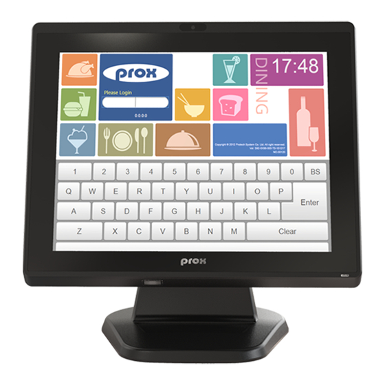
protech PA-J581 Series Slim POS Terminal Manuals
Manuals and User Guides for protech PA-J581 Series Slim POS Terminal. We have
1
protech PA-J581 Series Slim POS Terminal manual available for free PDF download: User Manual
protech PA-J581 Series User Manual (197 pages)
15”Fanless Slim POS Terminal Powered by Intel Celeron J6412 CPU Processor
Brand:
protech
| Category:
Touch terminals
| Size: 17 MB
Table of Contents
Table of Contents
4
Revision History
10
Introduction
11
About this Manual
12
POS System Overview
13
Panel PC
13
Normal Stand
14
Normal Stand with 15" 2Nd Display
15
Normal Stand with VFD
16
System Specifications
17
Safety Precautions
19
System Configuration
20
System External I/O Ports Diagram & Pin Assignment
21
Function Button and I/O Ports
22
Power Button
22
DC-IN Port
22
COM Ports (COM1, COM2, COM3)
22
Extension RJ45 COM Port (Option)
23
LAN Port (LAN)
24
HDMI Port Connector (HDMI)
25
Dual USB 3.0 Port Connector (USB1, USB2)
26
Dual USB 2.0 Port Connector (USB3, USB4)
27
Power Port Connector (24V PWR)
28
2Nd Display Power Port Connector (2ND-DIS PWR)
28
Extension Power USB 24V Port / Dual USB 2.0 Port
29
Cash Drawer Port (DRW)
30
Line out Audio Jack (Line-Out)
31
MIC in Audio Jack (MIC)
31
Main Board Component Locations & Jumper Settings
32
Jumper & Connector Quick Reference Table
34
Setting Jumpers
37
Setting Main Board Connectors and Jumpers
39
COM4 Connector (COM4)
40
LVDS VCC Voltage Selection (JP1)
41
LVDS BKLCTL PWM Voltage Level Selection (JP2)
42
LVDS BKLCTL PWM Fix Voltage Selection (JP4)
43
LDVS BKLCTL PWM Selection (JP5)
44
LVDS BKLTEN Voltage Level Selection (JP6)
44
Drawer Ports (DRW1, DRW1-1, DRW1-2)
45
Dual Cash Drawer Selection with Y-Cable (JP7)
45
Cash Drawer Voltage Selection (JP3)
46
USB3 Port Selection (JP_USB3)
49
USB4 Port Selection (JP_USB4)
49
USB5 Port Selection (JP_USB5)
50
USB7 Port Selection (JP_USB7)
50
USB8 / M.2 Selection (JP_USB8)
51
USB5 Connector (USB5)
52
Internal USB Wafers
53
VGA Connector (JVGA1)
57
EDP Connector (EDP1)
58
LVDS Connector (LVDS1)
59
Slide Switch for LVDS Resolution Selection (SW2)
60
General-Purpose Input / Output Connector (GPIO1)
66
On Board Touch Wafer (JTOUCH1)
66
DC 5V Power Connector (VOUT_5)
68
Power Button Wafer (JPWRBTN1)
68
System LED Wafer (JSYS_LED1)
69
Audio Connector (AUDIO1)
69
Speaker Wafer (SPK1)
69
System Reset Wafer (JRST1)
70
Panel Inverter Wafer (INV1)
71
I2C Wafer (I2C1)
71
Battery Wafer (JBAT1)
72
Clear CMOS Data Selection (JCMOS1)
73
VFD Board Component Locations & Pin Assignment
74
VFD Board: MB-4003
74
Jumper & Connector Quick Reference Table
74
Setting MB-4003 VFD Board Connector and Jumper
75
Power Switch Selection (JP12V)
75
Serial Interface Connector (CN1)
75
Software Utilities
76
Driver
77
Introduction
77
Intel ® Chipset Software Installation Utility
78
Graphics Driver Utility
79
Intel ® Management Engine Components Installer Installation
80
LAN Driver Utility
81
Sound Driver Utility
82
Embedded Peripheral Devices
83
VFD: MB-4003 (RS-232) Commands List
83
OPOS Driver
84
Api
89
API Package Content
89
API Procedure
90
Cash Drawer
93
Watchdog Timer
94
Hardware Monitor
95
Digital IO Control
96
Device Power Control
97
API Function
98
Cash Drawer Function
98
Watch Dog Function
99
Hardware Monitor Function
100
Digital IO Control Function
102
Device Power Control Function
102
BIOS Operation
104
BIOS Setup
104
Accessing Setup Utility
105
Main
107
Advanced
108
Advanced - CPU Configuration
109
Advanced - PCH-FW Configuration
111
Advanced - Trusted Computing
112
Advanced - ACPI Settings
113
Advanced - F81967 Super IO Configuration
114
Advanced - Hardware Monitor
119
Advanced - F81967 Watchdog Configuration
122
Advanced - S5 RTC Wake Settings
123
Advanced - USB Configuration
124
3.5.3.10 Advanced - Network Stack Configuration
125
Advanced >Nvme Configuration
126
Chipset
127
Chipset - System Agent (SA) Configuration
128
Chipset - PCH-IO Configuration
130
Security
136
Boot
137
Save & Exit
138
Appendix A System Diagrams
140
HDD Tray Disassembly
141
2Nd Display Module Assembly
142
VFD Module Assembly
146
MSR Module Assembly
150
I-Button Module Assembly
151
Fingerprint Module Assembly
152
Connecting 60W Power Adapter
153
Connecting 90W Power Adapter
156
Front Cover Module Assembly Exploded Diagram (2
159
Front Cover Module Assembly Exploded Diagram
160
Rear Cover Assembly Exploded Diagram (1
161
Rear Cover Assembly Exploded Diagram (2
162
LCD Case Assembly Exploded Diagram
163
Exploded Diagram for Panel PC HDD Assembly
164
LCD Assembly Exploded Diagrams (1
165
LCD Assembly Exploded Diagrams (2
166
Main Board Assembly Exploded Diagram
167
LCD Holder Assembly Exploded Diagram (1
168
LCD Holder Assembly Exploded Diagram (2
169
LCD Holder Assembly Exploded Diagrams (4
170
Barcode Scanner Kit Exploded Diagram
172
I/O Ports Cover Assembly Exploded Diagram
173
HDD Module Exploded Diagram
174
AL Cover Module and CPU Heatsink Exploded Diagram
175
Appendix B Technical Summary
176
Block Diagram
176
Interrupt Map
178
I/O Map
190
Memory Map
191
Configuring Watchdog Timer
193
Flash BIOS Update
195
Advertisement
Advertisement
Related Products
protech prox PA-J500
protech prox PA-J510
protech prox PA-J511
protech prox PA-J600
protech PA-J580 Series
protech PA-J501
protech PA-3170 Series
protech PA-3320
protech PA-3310
protech PA-3110
protech Categories
Toy
Touch terminals
Computer Hardware
Desktop
Touch Panel
More protech Manuals
Login
Sign In
OR
Sign in with Facebook
Sign in with Google
Upload manual
Upload from disk
Upload from URL