Sign In
Upload
Manuals
Brands
Edwards Manuals
Water Pump
nEXT300
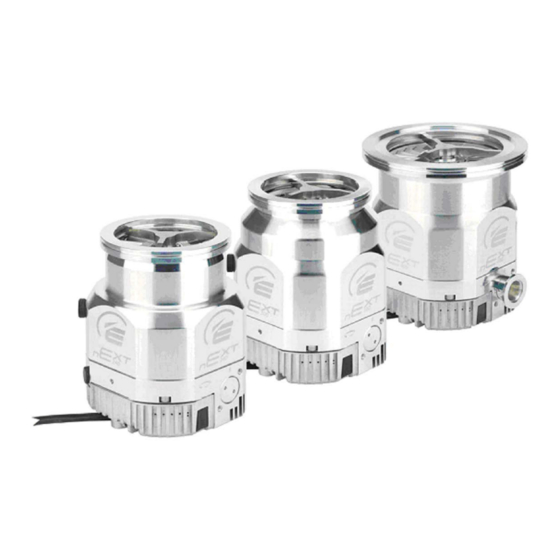
Edwards nEXT300 Manuals
Manuals and User Guides for Edwards nEXT300. We have
3
Edwards nEXT300 manuals available for free PDF download: Instruction Manual
Edwards nEXT300 Instruction Manual (108 pages)
Turbomolecular Pump
Brand:
Edwards
| Category:
Water Pump
| Size: 2.76 MB
Table of Contents
Table of Contents
3
Safety and Compliance
8
Definition of Warnings and Cautions
8
Safety Symbols
9
Trained Personnel
9
Introduction
11
Overview
11
Pump Model Description
12
Pump Controller
12
Figure 1 Pump Model Description
12
Operational Features
13
Power Limit Setting
13
Standby Speed
13
Timer
14
Analogue Output
14
Automatic Vent Options
15
Normal Speed Setting
15
Logic Interface
15
Parallel Control and Monitoring
16
Serial Control and Monitoring
16
Serial Control with Parallel Monitoring
16
Parallel Control with Serial Monitoring or Serial Configuration
17
Controller Configuration (Serial Configuration)
17
Technical Data
18
General Technical Data
18
Figure 2 Next240 Performance Curve
22
Figure 3 Next300 Performance Curve
23
Figure 4 Next400 Performance Curve
23
Figure 5 Next 240 Dimensions (MM)
24
Figure 6 Next 300 Dimensions (MM)
25
Figure 7 Next 400 Dimensions (MM)
26
Operation and Storage Environment
27
Vent Gas Specification and Vent Control Data
27
Purge Gas Specification
28
Cooling Water
28
Figure 8: Max Allowed Rate of Pressure Rise During Venting: Pressure against Time
28
Electrical Data
29
Pumping Media
29
Materials Exposed to Gases Pumped
31
Logic Interface Connector
31
Controller Connector Socket
34
Figure 9 Interface Circuits for Next Turbo Pump Controllers
34
Indicator Led's
35
Figure 10 Controller Connector Showing Pin Numbers
35
Installation
37
Unpack and Inspect
37
Typical Installation
38
Connect to the Vacuum System
38
Inlet Screen (Installed on CF Only)
39
Figure 11 Typical Pumping System with a Next Pump
39
Mechanical Fixing
40
Inlet Connection and Orientation
41
Figure 12 Installation Orientation
41
Base Mounting
42
Backing Port Connection
42
Interstage Connection (Variants Only)
43
Purge Gas Connection
43
Recommended Purge Gas Flow
43
Connect the Purge Gas
43
Electrical Installation
43
Ground the Connections
44
Connect the Logic Interface to the TIC
44
Connect the Logic Interface to the Customer Control Equipment
44
Connect the Electrical Supply
45
Connect the Parallel Control and Monitoring
46
Figure 13 Logic Interface Connections - Parallel Control
46
Connection for Serial Control and Monitoring
47
Connect the Serial Interface to the Customer Control Equipment
47
Figure 14 Controller Status Information
48
Serial Enable
49
Figure 15 Logic Interface Connections - RS232 Serial Control
49
Figure 16 Logic Interface Connections - RS485 Serial Control
49
Serial Protocol
50
Figure 17 Conceptual Diagram for Multi-Drop Connection Using RS232 Interface
51
Message Structure
52
Command Set
52
Figure 18 RS485 Multi-Drop Connection
52
Multi-Drop Operation
55
Connection for Mixed Parallel and Serial Operation
56
Vent Options, Vent Valve Connection and Control
57
Figure 19 Logic Interface Connection - Mixed Parallel and Serial Operation
57
Manual Vent Valve
58
TAV5 or TAV6 Solenoid Vent Valve
58
Vent Valve Control
59
Alternative Valve Connected to the Vacuum System
60
Cooling
60
Introduction
60
Forced Air Cooling
61
Water Cooling
61
Figure 20 Maximum Relative Humidity to Avoid Condensation with Water Cooling
62
Configuration
63
Configure the Pump Using Serial Commands
63
Power Limit Setting
63
Power Supply to the Fan from the Controller
64
Controlled Venting Options
64
Standby Speed Setting
65
Normal Speed Setting
65
Timer Setting and Options
66
Analogue Signal Options
67
Factory Settings
67
Assigning a Multi-Drop Address
67
Configuring the Next Pump Using a TIC
68
Operation
70
Before Starting the Pump
70
Close the Vent Valve
70
Pre-Start Sequence
70
Operation with Parallel Control and Monitoring
71
Start the Pump
71
Running at Standby Speed
71
Stop the Pump
71
Parallel Monitoring
71
Operation with Serial Control and Monitoring
71
Delayed Start
71
Start the Pump
72
Standby Speed
72
Stop the Pump
72
Temperature Readings
73
Link Parameter Readings
73
Measured Motor Speed
73
Mixed Parallel and Serial Operation
74
Operation with a TIC
75
Decelerating and Venting
75
Figure 21 Serial and Parallel Control Flowchart
75
Operation at Extreme Conditions
76
Operation with High Inlet Pressure
76
Operation at High Temperatures
76
Protection against Over-Speed
76
Electrical Supply Failure
77
Bakeout
77
Maintenance
80
Introduction
80
Bearing and Oil Cartridge Maintenance
80
Rotor Life
80
Clean the External Surfaces of the Pump
81
Fault Finding
82
Flashing Service Codes
85
Decoding Service Status Words
86
Controller Run Time
87
Pump Run Time
87
Pump Cycles
87
Bearing Run Time
88
Oil Cartridge Run Time
88
Flashing Error Codes
88
Decoding System Status Words
89
Useful Service Information
91
Storage
93
Disposal
94
Service
95
Return the Equipment or Components for Service
95
Bearing and Oil Cartridge On-Site Maintenance
96
Spares
97
ISX Inlet Screen
97
Inlet Strainer
97
Inlet-Flange Seals and Integrated Inlet Screens
97
NW16 and NW25 Ports
98
Accessories
99
Installation
99
Figure 22 Next Exploded Accessories View
99
ACX Air Cooler
100
Figure 23 Next Exploded Accessories View
100
WCX Water Cooler
101
BX Bakeout Band
101
TAV Vent Valve and Vent Port Adaptor
101
VRX Vent Restrictor
101
Vent Port Adaptor
102
PRX Purge Restrictor
102
C-Clamp Adaptor Kit
102
Interface Cable
103
TIC PC Program
103
Advertisement
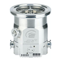
Edwards nEXT300 Instruction Manual (81 pages)
Turbomolecular Pumps
Brand:
Edwards
| Category:
Water Pump
| Size: 2.8 MB
Table of Contents
Table of Contents
3
Introduction
8
Scope and Definitions
8
General Description
9
Pump Controller
10
Operational Features
10
Power Limit Setting
10
Standby Speed
10
Timer
11
Analogue Output
11
Automatic Vent Options
11
Normal Speed Setting
12
Logic Interface
12
Parallel Control and Monitoring
12
Serial Control and Monitoring
12
Serial Control with Parallel Monitoring
13
Parallel Control with Serial Monitoring or Serial Configuration
13
Controller Configuration (Serial Set-Up)
13
Technical Data
14
General
14
Pumping Media
14
Next240 Performance Curve
19
Next300 Performacne Curve
19
Next 240D Dimensions (MM)
21
Next 300D Dimensions (MM)
22
Next 400D Dimensions (MM)
23
Vent Gas Specification and Vent Control Data
24
Purge Gas Specification
25
Cooling Water
25
Materials Exposed to Gases Pumped
25
Electrical Data
26
Logic Interface Connector
26
Controller Connector Socket
27
Maximum Allowed Rate of Pressure Rise During Venting: Pressure against Time (with Pump Initially at Full Rotational Speed) 17 7 Controller Connector Showing Pin Numbers
28
Interface Circuits for Next Turbo Pump Controllers
29
Indicator Leds
30
Operating and Storage Environment
30
Installation
32
Unpack and Inspect
32
Typical Installation
32
Connection to the Vacuum System
33
Typical Pumping System with a Next Pump
33
Inlet-Screen (Supplied Fitted on CF Only)
34
Mechanical Fixing
34
Inlet-Connection and Orientation
34
Base Mounting
35
Backing Connection
35
Interstage Connection (Variants Only)
36
Purge Gas Connection
36
Connect the Purge Gas
36
Recommended Purge Gas Flow
36
Electrical Installation
36
Introduction
36
Earth (Ground) Connections
36
Connect the Logic Interface to the TIC
36
Connect the Logic Interface to Your Control Equipment
37
Connect the Electrical Supply
37
Connection for Parallel Control and Monitoring
38
Logic Interface Connections - Parallel Mode
38
Connection for Serial Control and Monitoring
39
Connect the Serial Interface to Your Control Equipment
39
Controller Status Information
40
Serial Enable
41
Serial Protocol
42
Message Structure
43
Command Set
44
Simultaneous Parallel and Serial Operation
46
Schematic Diagram of the Logic Interface Connections
46
Multi-Drop Operation
47
Vent Options, Vent Valve Connection and Control
47
Manual Vent Valve
47
TAV5 or TAV6 Solenoid Vent Valve
47
Controlled Venting
48
Alternative Valve Connected to the Vacuum System
49
Cooling
49
Introduction
49
Forced Air Cooling
49
Water-Cooling
50
Maximum Relative Humidity to Avoid Condensation with Water Cooling
50
Operation
52
Configuring the Next Pump Using Serial Commands
52
Power Limit Setting
52
Powering a Fan from the Controller
53
Controlled Venting Options
53
Standby Speed Setting
54
Normal Speed Setting
54
Timer Setting and Options
55
Analogue Signal Options
56
Factory Settings
56
Assigning a Multi-Drop Address
56
Configuring the Next Pump Using a TIC
57
Start-Up
58
Close the Vent Valve
58
Pre-Start Checks
58
Operation with Parallel Control and Monitoring
59
Start the Pump
59
Running at Standby Speed
59
Stop the Pump
59
Parallel Monitoring
59
Operation with Serial Control and Monitoring
59
Delayed Start
59
Start the Pump
60
Standby Speed
60
Stop the Pump
60
Temperature Readings
60
Link Parameter Readings
61
Measured Motor Speed
61
Simultaneous Parallel and Serial Operation
61
Operation with a TIC
61
Decelerating and Venting
61
Operation at Extreme Conditions
62
Operation with High Inlet Pressure
62
Operation at High Temperatures
62
Operation at Over-Speed
62
Electrical Supply Failure
62
Bakeout
63
Maintenance
66
Introduction
66
Bearing and Oil Cartidge Maintenance
66
Rotor Life
66
Clean the External Surfaces of the Pump
67
Fault Finding
67
Flashing Service Codes
70
Flashing Error Codes
70
Decoding System Status Words
71
Useful Service Information
73
Storage and Disposal
74
Storage
74
Disposal
74
Service, Spares and Accessories
76
Introduction
76
Service
76
Returning a Pump for Service
76
Bearing and Oil Cartridge On-Site Maintenance
76
Spares
77
ISX Inlet-Screen
77
Inlet-Strainer
77
Inlet-Flange Seals and Integrated Inlet Screens
77
Accessories
77
Installation
77
ACX Air-Cooler
77
WCX Water-Cooler
78
BX Bakeout Band
78
TAV Vent-Valve and Vent-Port Adaptor
78
VRX Vent-Restrictor
78
Vent-Port Adaptor
79
PRX Purge-Restrictor
79
Next Exploded Accessories View
80
Next Exploded Accessories View
81
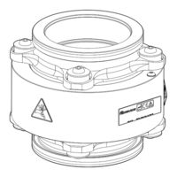
Edwards nEXT300 Instruction Manual (20 pages)
Vibration Isolator Turbomolecular Pumps
Brand:
Edwards
| Category:
Water Pump
| Size: 0.94 MB
Table of Contents
Table of Contents
3
Safety and Compliance
5
Definition of Warnings and Cautions
5
Safety Symbols
6
Trained Personnel
6
Introduction
7
Overview
7
Figure 1 General View of the Vibration Isolator
7
Technical Data
8
Figure 2 Axial Transmission Function of Isolator
8
Figure 3 Radial Transmission Function of Isolator
9
Storage
10
Installation
11
Installation Safety
11
Unpack and Inspect
11
Install the Vibration Isolator
12
Figure 4 Installation Orientation
13
Maintenance
14
Maintenance Safety
14
Maintenance Plan
14
Service
15
Return the Equipment or Components for Service
15
Legal Declarations
17
Advertisement
Advertisement
Related Products
Edwards nEXT300T
Edwards nEXT300D
Edwards T-Station nEXT300D CF100
Edwards nEXT series
Edwards nEXT400
Edwards nEXT400D
Edwards nEXT400T
Edwards nEXT240D
Edwards nEXT200200
Edwards nEXT730D
Edwards Categories
Water Pump
Control Unit
Measuring Instruments
Controller
Medical Equipment
More Edwards Manuals
Login
Sign In
OR
Sign in with Facebook
Sign in with Google
Upload manual
Upload from disk
Upload from URL