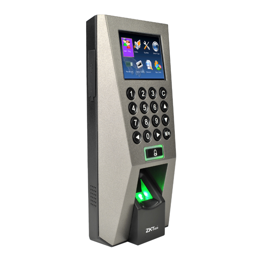
ZKTeco F18 - IP Access Controller Installation Guide
- User manual (96 pages) ,
- Quick start manual (19 pages) ,
- Installation manual (2 pages)
Advertisement
Equipment Installation
- Post the mounting template on the wall. Drill the holes according to the marks on the template (holes for screws and wiring).
.")
- Remove the screw on the bottom of device.

- Take away the back plate.
![]()
- Fix the plastic pad and the back plate on the wall according to the mounting paper.

- Tighten the screw on the bottom, fix the device to the back plate.

.")


Structure and Function

Acess Control System Function
- If a registered user verified, the device will export the signal to unlock the door.
- Door sensor will detect the on-off state If the door is unexpected opened or improperly closed, the alarm signal (digital value) will be triggered.
- If the device is removed illegally, it will output an alarm signal.
- External card reader is supported.
- External exit button is supported, it is convenient to open the door inside.
- External door bell is supported.
- Supports RS485 TCP/IP, modes to connect with PC. One PC can manage multiple devices.
Lock Connection
- Share power with the lock

Device shares power with the lock:
ULOCK=12V, I-ILOCK>1A![]()
![]()
And the distance between the lock and the device is equal or less than 10 meters.
![]() : 'I': device output current, 'ULOCK': lock voltage, ' ILOCK': lock current
: 'I': device output current, 'ULOCK': lock voltage, ' ILOCK': lock current - Does not share power with the lock

Does not shares power with the lock:
- ULOCK=12V I-ILOCK≤1A;
- ULOCK ≠12V;
- The distance between the lock and the device is more than 10 meters.


- The system supports NO LOCK and NC LOCK. For example, the NO LOCK (normally open at power on) is connected with 'NO' and COM terminals, and the NC LOCK (normally close at power on) is connected with 'NC' and COM' terminals.
- When the Electrical Lock is connected to the Access control System, you need to parallel one FR107 diode (equipped in the package) to prevent the self-inductance EMF affecting the system, do not reverse the polarities.
Other Parts Connection

Power Connection
Input DC 12V, 500mA (50mA standby). Positive is connected with '+12V', negative is connected with 'GND' (do not reverse the polarities).

Wiegand Output
The device supports standard Wiegand 26 / Wiegand 34 output, so you can connect it with most of the access control devices by now.

Wiegand Input
The device has the function of Wiegand signal input. It supports to connect with an independent card reader.
They are installed each side of the door, to control the lock and access together.

- Please keep the distance between the device and access control or card reader less than 90 meters(Please use Wiegand signal extender in long distance or interference environment).
- To keep the stability of Wiegand signal, connect the device and the access control or card reader in same 'GND' in any case.
Other Functions
Manual Reset:
If the device does not work properly because of misoperation or other abnormality, you can use 'Reset' function to restart it.
Operation: Remove the black rubber cap, then stick the Reset button hole with a sharp tool (the tip diameter is less than 2mm).

Restore Factory Settings:
You can use the tamper switch to restore factory settings, such as device number, system password, IP address, RS485 address.etc.
The user data won't be cleared.
Operation: Press the tamper switch three times after the alarm being triggered 30 seconds, but no more than 60 seconds.

Communication
There are three modes that the PC software could communicate and exchange information with the device RS232, RS485 and TCP/IP, and the last two modes support remote control.
RS232 Mode:
Terminals definition, please refers to the right table:
| Terminals | PC Serial Ports |
| GND | Pin5-Gnd |
| RXD | Pin3-Txd |
| TXD | Pin2-Rxd |

No operating with power on
RS485 Mode:
Please use specified RS485 wire, RS485 active converter and bus-type wiring.
Terminals:
| Terminals | PC Serial Ports |
| 485+ | RS485+ |
| 485- | RS485- |
TCP/IP Mode:
About the terminals definition, please refers to the right table.
Two ways for TCP/IP connection:
- Crossover cable: The device and PC connected directly.

IP Address:192.168.1.100
Subnet Mask:255.255.255.0
IP Address:192.168.1.124
Subnet Mask:255.255.255.0


| Terminals | Wire Name | Color |
| RJ45-1 | TX+ | White-orange |
| RJ45-2 | TX- | Orange |
| RJ45-3 | RX+ | White-green |
| RJ45-6 | RX- | Green |
- Straight cable: The device and PC connected to LAN/WAN through switch/Lanswitch.
![]()

Cautions
- Power cable is connected after all the other wiring. If the device is operated abnormally, please shut down the power firstly, then make some necessary checking. Kindly remain that any hot plugging may damage device, and it is not included in the warranty.
- We recommend that use the DC 3A/12V power supply. For details, please contact our technical personnel or sales.
- Please read the terminals description carefully and wiring by rule strictly. Any damage caused by improper operations will be out of the range of our guarantee.
- Keep the exposed part of wire is less than 5mm to avoid unexpected connection, and result in machinery damage.
- Please connect the GND before all the other wiring especially under the serious electrostatic environment, to prevent the overlarge instantaneous electrostatic to damage device.
- If the distance between power supply and device is a little long, please do not use the Internet cable or other types of cable instead. When choosing the power supply cable, you should consider that the transmission distance may cause voltage attenuation.
- Please use specified RS485 wire, RS485 active converter, and adopt bus-type wiring. If the communication wire is longer than 100 meters, it is needed to parallel a terminal resistance on the last device of RS485 bus, and the value is about 120 ohm.
Documents / ResourcesDownload manual
Here you can download full pdf version of manual, it may contain additional safety instructions, warranty information, FCC rules, etc.
Download ZKTeco F18 - IP Access Controller Installation Guide
Advertisement


Need help?
Do you have a question about the F18 and is the answer not in the manual?
Questions and answers