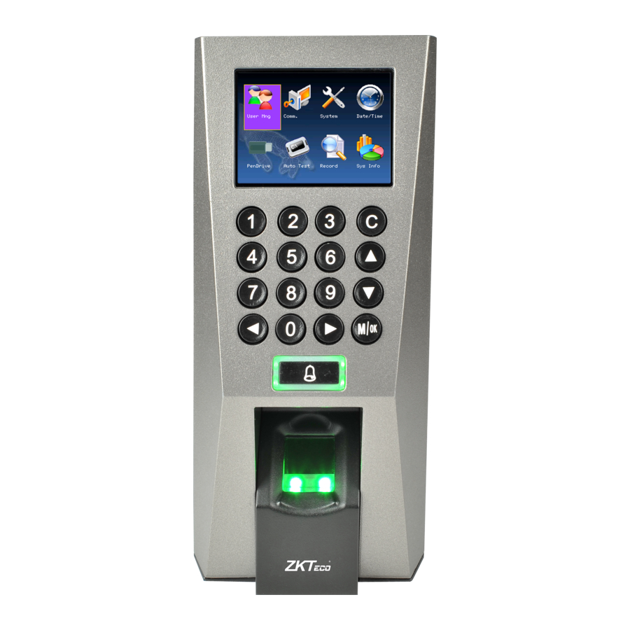
ZKTeco F18 Quick Start Manual
2.4 inch color screen
Hide thumbs
Also See for F18:
- Installation manual ,
- User manual (96 pages) ,
- Quick start manual (11 pages)
Table of Contents
Advertisement
Quick Links
Features:
1. 2.4" TFT-LCD color screen
2. Standard Wiegand Input and Output interfaces are compatible with most all 3
bit Wiegand readers and access control panels.
3. USB HOST port makes offline data backup/management fast & easy.
4. Relay contacts for alarm, electric lock, exit button, and wired door bell.
5. Reads fingerprint and Password.
Specifications:
Fingerprint capacity
Transaction capacity
Hardware Platform
Fingerprint Sensor
LED Indicator
Communication
Wiegand signal
Identification speed
Operating Temperature
Operating Humidity
Power Supply
Access control interfaces
Basic Contents:
F18 Fingerprint
Terminal
2.4 Inch Color Screen Quick Start Guide
CPU
Memory
Display
FAR
FRR
Language
Dimension
Metallic Mounting Plate
3,000
100,000
ZEM720
ZK 6001, 400Mhz
64M Flash, 32MSDRAM
ZK optical sensor
2.4" TFT LCD color screen
Red, Green
Ethernet(10/100M), RS485, USB-
HOST,
Wiegand Input and Wiegand Output
≤2 sec
≤0.0001%
≤1%
0-45℃
20%-80%
English, Spanish, Portuguese, French...
12V DC, 3A
Electric lock, alarm, exit button, wired
door bell
80*183*42mm (L*W*D)
Wall Mounting Screws and
Holders
rd
party 26-
Advertisement
Table of Contents

Related Manuals for ZKTeco F18


Summary of Contents for ZKTeco F18
- Page 1 Operating Humidity 20%-80% Language English, Spanish, Portuguese, French… Power Supply 12V DC, 3A Access control interfaces Electric lock, alarm, exit button, wired door bell Dimension 80*183*42mm (L*W*D) Basic Contents: Wall Mounting Screws and Holders F18 Fingerprint Metallic Mounting Plate Terminal...
- Page 2 Star-shape Screw Driver Star-shape Screw for Mini-USB Cable Mounting Plate Installation Guide Mounting Paper Software CD Optional Accessories Alarm Indicator FR1200 Fingerprint Slave K1 Exit Button Reader Power Supply Electric Strike Lock Electric Magnetic Lock Controller 12V3A Power Adaptor Mifare USB Memory Integrated Module and Card Front...
- Page 3 Side Rear...
- Page 4 Installation Diagram Product Dimensions (mm)
- Page 5 Cable Specification...
- Page 6 Use regulated 12V DC 3A power source (supplied from control panel or separately purchased power supply). Do not place the F18 in a vulnerable location where it might be subjected to vandalism. Mounting the Unit Locate the appropriate area for the unit. Place the unit approximately 5 ½ feet above...
- Page 7 the ground level so that the users are comfortable in using the unit with fewer chances of errors. Create conduits for the power and network cable on the wall so that the unit receives the connections from the back of the wall. ...
- Page 8 Press ESC to cancel the operation and return to the previous menu. User Enrollment To start user enrollment, press the Menu key on the F18, it will prompt From the Main Menu, highlight and select User Mng to add/change/delete users’...
- Page 9 ID. NO (Account Number) Unique identification number associated with each user. Fingerprint (FP) A user can enroll up to 10 fingerprints. Password (PWD) A user can enroll a password using 1 to 8 characters. Security/Authority (Purview) Identifies a user as a normal user or an Administrator. a) Add New User ID.
- Page 10 Notice “Enroll FP” will become highlighted. Press OK to accept selection. Remember the rules for proper finger placement; The user’s finger should completely cover the sensor. The finger should be placed flat and in the center of the sensor. The finger should cover at least 80% of the sensor as shown below: The finger should NOT be placed in the following positions: Not flat Not centered...
- Page 11 Place the finger you wish to enroll on the sensor, ensuring the finger is placed flat and centered. Hold the finger still for at least two full seconds until the F18 prompts with a beep to remove it. You will then be prompted to repeat the process 2 more times, each time using the very SAME finger.
- Page 12 In the “Input Pwd” field, enter a password of 1 to 8 characters. Then scroll down to the “Pwd Affirm” field and re-enter the same password. After completed, scroll with the ▲/▼keys until OK (M/<-) is highlighted. Then press the OK key to accept.
- Page 13 Users have unrestricted access to the F18 menu settings (i.e. Add/Edit/Delete users). For this reason, we advise enrolling an “administrator” after initial installation to help ensure safeguarding both the F18(s) and the customer door entrance(s). From within the New User Menu, scroll with the ▲/▼keys until the cursor is in the Purview field.
- Page 14 Select the user you’d like to delete by scrolling with the ▲/▼ keys. Then press the Menu key so the drop-down menu appears; Use the ▲/▼scroll keys and highlight “Del User”. Then press the OK key to select. The following Delete User screen appears; You can delete either the user, fingerprint, password or the ID card.
- Page 15 The F18 will prompt you “OKDel”? Press the OK again to confirm deletion. Set Communications Options: The F18 can communicate via the Network (Ethernet), RS/232 or RS485. Network (Ethernet) Press the Menu key to open the Main menu; From the Main Menu, highlight and select Comm. to configure Communication Settings.
- Page 16 Machine IP address: Default IP is 192.168.1.239. You can modify it. But do NOT use an IP address already being used by another network device. Subnet mask: Default mask 255.255.255.0. You can modify it. Gateway address: Default gateway address is 0.0.0.0. You can modify it. Network speed: Note 3 Options (Automatic, 10M and 100M) Scroll with the ▲...
- Page 17 From the Main Menu, highlight and select Comm. to configure Communication Settings. Then press the OK Key to accept From within the Comm Menu, scroll with the / keys until RS232/485 is highlighted. Press the OK key to accept. Notice the following “RS232/485” settings are available...
- Page 18 Baud rate: Use the / to change pre-set values. RS232: If using RS232 communication, select “On”. RS485: If using RS485 communication, select “On”. Scroll with the ▲/▼ keys to place the cursor in the desired field. Use the scroll keys ◄/► keys to change between pre-defined values. After making changes, either press the OK key, or highlight the OK (M/) button and then press the OK Key.
Need help?
Do you have a question about the F18 and is the answer not in the manual?
Questions and answers