Table of Contents
Advertisement
Quick Links
2-Port Serial-to-IP Ethernet Device Server - RS232
NETRS2322P
FR: Guide de l'utilisateur - fr.startech.com
DE: Bedienungsanleitung - de.startech.com
ES: Guía del usuario - es.startech.com
NL: Gebruiksaanwijzing - nl.startech.com
PT: Guia do usuário - pt.startech.com
IT: Guida per l'uso - it.startech.com
For the latest information, technical specifications, and support for
this product, please visit www.startech.com/NETRS2322P
Manual Revision: 09/13/2017
*actual product may vary from photos
Advertisement
Table of Contents

Related Manuals for StarTech.com NETRS2322P


Summary of Contents for StarTech.com NETRS2322P
- Page 1 2-Port Serial-to-IP Ethernet Device Server - RS232 NETRS2322P *actual product may vary from photos FR: Guide de l’utilisateur - fr.startech.com DE: Bedienungsanleitung - de.startech.com ES: Guía del usuario - es.startech.com NL: Gebruiksaanwijzing - nl.startech.com PT: Guia do usuário - pt.startech.com IT: Guida per l’uso - it.startech.com...
- Page 2 StarTech.com. Where they occur these references are for illustrative purposes only and do not represent an endorsement of a product or service by StarTech.com, or an endorsement of the product(s) to which this manual applies by the third-party company in question. Regardless of any direct acknowledgement elsewhere in the body of this document, StarTech.com hereby...
-
Page 3: Table Of Contents
Table of Contents Introduction ....................1 Packaging contents ..........................1 Requirements ............................. 1 Product diagram ..................2 Front view ..............................2 Rear view ..............................2 DB9 RS232 connector pinout ....................... 2 Install the device server ................3 Install the device server using the power adapter ................ 3 Install the device server using the terminal block ................ -
Page 4: Introduction
Virtual COM software is not compatible with these operating systems. When used with a Mac or Linux operating system, the device server can only be configured using the web GUI. Operating system requirements are subject to change. For the latest requirements, please visit www.startech.com/NETRS2322P. Instruction manual... -
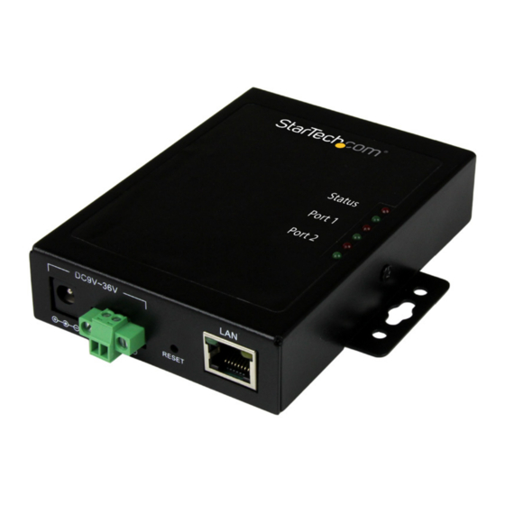
Page 5: Product Diagram
Product diagram Front view LEDs 2-wire terminal Reset button block (9~36V DC input) DC power 10/100Mbps input RJ45 port Rear view Surface mount DB9 RS232 Surface mount serial ports DB9 RS232 connector pinout Pin 1 Pin 2 Pin 3 Pin 4 Pin 5 Pin 6 Pin 7... - Page 6 About the LED indicators Behavior Indication Status is normal, the device Solid server is powered Status (Green) Internal software is loaded but Blinking not running Internal software is not loaded Status (Red) Blinking or is damaged Firmware is not loaded or is Status (Green and Red) Blinking and alternating damaged...
-
Page 7: Install The Device Server
Install the device server The device server can be powered using the provided power adapter, or using the terminal block power input (9~36V DC). You can also use redundant power input by connecting both the power adapter and terminal block power. If one of your power sources fails, the device server will switch to the secondary power source. -
Page 8: Configure The Device Server
Install and configure the EMT Connection Wizard (Windows only) 1. To download the latest software, use a web browser and navigate to http://www.startech.com/NETRS2322P. 2. Click the Support tab. 3. Download the software. 4. When the download is complete, extract the contents of the compressed file(s) that you downloaded. -
Page 9: Configure Using The Web Gui (Windows, Mac, And Linux)
6. On the following screen, click Next. 7. Select a Channel and click Next. Channel 1 is for the device server’s serial port 1, Channel 2 is for the device server’s serial port 2. 8. Select which side will need to send the data first (for example, setting the device server as a client or as a host). -
Page 10: Surface Or Wall Mounting
4. Press and hold the Factory reset button until the device server beeps twice. 5. Wait thirty seconds and disconnect any power sources from the device server and reassemble the housing. Note: The Reset button on the outside of the device server is a hardware reset that reboots the device server. -
Page 11: Technical Support
Limitation of Liability In no event shall the liability of StarTech.com Ltd. and StarTech.com USA LLP (or their officers, directors, employees or agents) for any damages (whether direct or indirect, special, punitive, incidental, consequential, or otherwise), loss of profits, loss of business, or any pecuniary loss, arising out of or related to the use of the product exceed the actual price paid for the product. - Page 12 StarTech.com is an ISO 9001 Registered manufacturer of connectivity and technology parts. StarTech.com was founded in 1985 and has operations in the United States, Canada, the United Kingdom and Taiwan servicing a worldwide market.
Need help?
Do you have a question about the NETRS2322P and is the answer not in the manual?
Questions and answers