Table of Contents
Advertisement
Advertisement
Table of Contents

Related Manuals for StarTech.com 13-SERIAL-ETHERNET


Summary of Contents for StarTech.com 13-SERIAL-ETHERNET
- Page 1 1-Port RS232 Serial Over IP Device Server Actual product may vary from photos User Manual SKU#: I13-SERIAL-ETHERNET / I13P-SERIAL-ETHERNET For the latest information and specifications visit www.StarTech.com/I13-SERIAL-ETHERNET / www.StarTech.com/I13P-SERIAL-ETHERNET Manual Revision: 07/30/2024...
-
Page 2: Compliance Statements
This manual may make reference to trademarks, registered trademarks, and other protected names and/or symbols of third-party companies not related in any way to StarTech.com. Where they occur these references are for illustrative purposes only and do not represent an endorsement of a product or service by StarTech.com, or an endorsement of the product(s) to which this manual... -
Page 3: Safety Statements
• 電源が入っている状態の製品または電線の終端処理を行わないでくださ い。 • ケーブル (電源ケーブルと充電ケーブルを含む) は、 適切な配置と引き回し を行い、 電気障害やつまづきの危険性など、 安全上のリスクを回避するよう にしてください。 Misure di sicurezza • I terminiali dei fili elettrici non devono essere realizzate con il prodotto e/o le linee elettriche sotto tensione. • I cavi (inclusi i cavi di alimentazione e di ricarica) devono essere posizionati e stesi in modo da evitare pericoli di inciampo, rischi di scosse elettriche o pericoli per la sicurezza. Säkerhetsåtgärder • Montering av kabelavslutningar får inte göras när produkten och/eller elledningarna är strömförda. • Kablar (inklusive elkablar och laddningskablar) ska dras och placeras på så sätt att risk för snubblingsolyckor och andra olyckor kan undvikas. To view manuals, videos, drivers, downloads, technical drawings, and more visit www.startech.com/support... -
Page 4: Table Of Contents
Use the Software to Discover the Serial Device Server ............... 10 Configure the Serial Port Settings ....................... 12 Changing COM Port or Baud Rate in Windows ................15 LED Chart ..............................16 Factory Reset Procedure ......................... 17 To view manuals, videos, drivers, downloads, technical drawings, and more visit www.startech.com/support... -
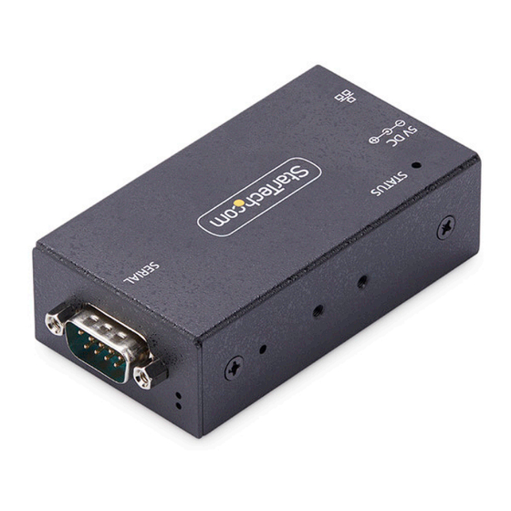
Page 5: Product Diagram
• Install the DIN Rail Kit or Wall Mounting Bracket using the included Mounting Bracket Screws Mounting Bracket Holes • Two on each side and four on the bottom of the Serial Device Server To view manuals, videos, drivers, downloads, technical drawings, and more visit www.startech.com/support... -
Page 6: Rear View
• Connect an Ethernet Cable to the Serial Device Server • Supports 10/100Mbps Ethernet Port • Link/Activity LEDs: Refer to LED Chart • I13P-SERIAL-ETHERNET: Supports 802.3af to power the Serial Device Server To view manuals, videos, drivers, downloads, technical drawings, and more visit www.startech.com/support... -
Page 7: Product Information
• Network Protocol Mode: Telnet Server (RFC2217) • Serial Mode: RS-232 Factory Default Button Settings • IP Address: 192.168.5.252 • Password: admin • Network Protocol Mode: Telnet Server (RFC2217) • Serial Mode: RS-232 To view manuals, videos, drivers, downloads, technical drawings, and more visit www.startech.com/support... -
Page 8: Hardware Installation
1. Determine the mounting method that best suits the installation environment (DIN Rail or Wall Mount). 2. Align the bracket with the Bracket Mounting Holes on the bottom or sides of the Serial Device Server. To view manuals, videos, drivers, downloads, technical drawings, and more visit www.startech.com/support... -
Page 9: Software Installation
4. Extract the contents of the downloaded .zip file. 5. Run the extracted executable file to start the software installation. 6. Follow the on screen prompts to complete the installation. To view manuals, videos, drivers, downloads, technical drawings, and more visit www.startech.com/support... -
Page 10: Operation
Telnet server. 2. Type the IP address of the Serial Device Server. Note: This can be found using the StarTech.com Device Server Manager for Windows, or by viewing the connected devices on the local network router. 3. Connect to the Serial Device Server. -
Page 11: Use The Software To Discover The Serial Device Server
2. Click Auto Search to initiate the process of discovering Serial Device Servers on the local network. 3. Discovered Serial Device Servers will appear in the “Remote Server(s)” list in the right pane. To view manuals, videos, drivers, downloads, technical drawings, and more visit www.startech.com/support... - Page 12 All Servers” to add all discovered Serial Device Servers. 5. The Serial Device Servers will be mounted in Device Manager as “SDS Virtual Serial Port” with an associated COM port number. To view manuals, videos, drivers, downloads, technical drawings, and more visit www.startech.com/support...
-
Page 13: Configure The Serial Port Settings
Data Bits • 8 • None • Even Parity • Odd • Mark • Space • 1 Stop Bits • 2 • Hardware Flow Control • Software • None To view manuals, videos, drivers, downloads, technical drawings, and more visit www.startech.com/support... - Page 14 4. Select “Apply Changes” to save the settings. In the Web Interface 1. Open a web browser. 2. Type the IP address of the Serial Device Server into the address bar. To view manuals, videos, drivers, downloads, technical drawings, and more visit www.startech.com/support...
- Page 15 Number, and more. 6. Under “Set”, select “OK” to set the serial settings to the port. 7. Select “Save Changes” to save the settings to the Serial Device Server. To view manuals, videos, drivers, downloads, technical drawings, and more visit www.startech.com/support...
-
Page 16: Changing Com Port Or Baud Rate In Windows
4. Click Save Changes. 5. In the StarTech.com Device Server Manager, click the Serial Device Server which should still have the old COM Port number, then click Delete. 6. Re-add the Serial Device Server using “Add Selected Server” to add a specific Serial Device Server or “Add All Servers”... -
Page 17: Led Chart
• Off: No serial data is being transmitted or received • Steady Green: Power is On • Off: Power is Off Power/Status LED • Blinking Green: Restoring to Factory Defaults To view manuals, videos, drivers, downloads, technical drawings, and more visit www.startech.com/support... -
Page 18: Factory Reset Procedure
5 seconds. When the Status LED begins blinking, release the Factory Reset Button. The Status LED will then illuminate, indicating that the Serial Device Server is rebooting. Factory Reset Button To view manuals, videos, drivers, downloads, technical drawings, and more visit www.startech.com/support... - Page 19 Limitation of Liability In no event shall the liability of StarTech.com Ltd. and StarTech.com USA LLP (or their officers, directors, employees or agents) for any damages (whether direct or indirect, special, punitive, incidental, consequential, or otherwise), loss of profits, loss of business, or any pecuniary loss, arising out of or related to the use of the product exceed the actual price paid for the product.
- Page 20 Hard-to-find made easy. At StarTech.com, that isn’t a slogan. It’s a promise. StarTech.com is your one-stop source for every connectivity part you need. From the latest technology to legacy products — and all the parts that bridge the old and new — we can help you find the parts that connect your solutions.
Need help?
Do you have a question about the 13-SERIAL-ETHERNET and is the answer not in the manual?
Questions and answers