Table of Contents
Advertisement
Quick Links
Advertisement
Table of Contents

Subscribe to Our Youtube Channel
Related Manuals for Eaton Green Motion Air


Summary of Contents for Eaton Green Motion Air
- Page 1 Green Motion Air aircraft charger Green Motion Air Installation manual...
- Page 2 Corporation’s (“Eaton”) experience and judgment and may not cover all contingencies. If further information is required, an Eaton sales office should be consulted. Sale of the product shown in this literature is subject to the terms and conditions outlined in appropriate Eaton selling policies or other contractual agreement between Eaton and the purchaser.
-
Page 3: Table Of Contents
Positioning the Green Motion Air electric aircraft charger ....... . . - Page 4 MAINTENANCE ..............43 How to open/close the Green Motion Air electric aircraft charger housing ..... 43 How to set the unit as out of order .
-
Page 5: Introduction
The contents of this manual are the copyright of the publisher and may not be reproduced (even in extracts) without the prior written approval of Eaton. While every care has been taken to ensure the accuracy of the information contained in this manual, Eaton assumes no liability for any error or omission. Eaton reserves the right to modify the designs of its products. -
Page 6: Field Of Applications
This installation manual is intended for professional installers. It describes how to securely install and commission the Eaton Green Motion Air electric aircraft charger: Table 1. Green Motion Air electric aircraft charger overview Green Motion Air Green Motion Air Mobile... -
Page 7: Conventions Used In This Document
The EU Directive on Waste Electrical and Electronic Equipment (WEEE). 1.3 Conventions used in this document This manual adopts the following type conventions and acronyms to refer to Green Motion Air electric aircraft charger or its parts: ALL CAPITALS highlight critical points that require careful attention. -
Page 8: Cautions
Eaton sales representative. The unit must not be subjected to any type of modification. Eaton declines any responsibility if the rules for correct installation are not respected, and it is not responsible for the system upstream or downstream of the equipment it supplies. -
Page 9: Suggested Protections During The Installation
Eaton declines any responsibility if the unit is incorrectly installed. The operators must be correctly instructed. The operators must therefore read and follow the technical instructions contained in the manual and in the enclosed documentation. -
Page 10: Electromagnetic Fields And Interference
Professional and qualified personnel must be an expert in the field, and are therefore responsible for commissioning the product in accordance with the manufacturer’s instructions and local legislation. If electromagnetic interference is detected, the professional and qualified personnel should contact an Eaton technical support representative using the email address BGTechSupport@eaton.com. -
Page 11: General Description
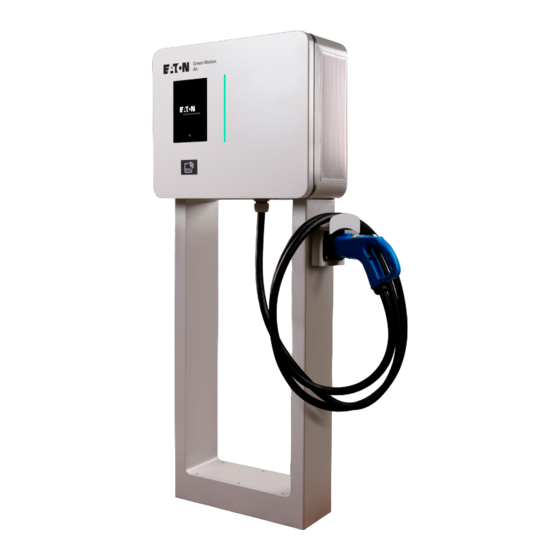
Title 3. General description The following images show different views of the Green Motion Air electric aircraft charger. 3.1 Front and back views Figure 1. Front and back views of Green Motion Air electric aircraft charger 49 mm 532 mm (1.9 inch) -
Page 12: Left And Right Views
Title 3.2 Left and right views Figure 2. Left and right views of Green Motion Air electric aircraft charger Description Air flow grid 3.3 Top and bottom views Figure 3. Top and bottom views of Green Motion Air electric aircraft charger... -
Page 13: Types Of Cables
The Green Motion Air aircraft charger is provided with a GB/T cable and connector (plug). The nominal output power of the Green Motion Air electric aircraft charger is 22 kW. However, the actual charging power may vary due to external factors such as the available grid power, capacity of the electrical installations, and the electric aircraft model. -
Page 14: Green Motion Air Mobile
3.5 Green Motion Air Mobile The Green Motion Air Mobile electric aircraft charger is shipped as a factory-preassembled kit consisting of a single Green Motion Air unit mounted on a mobile platform (trolley) and equipped with an AC power supply cable (15 m). -
Page 15: Relevant Information Prior To The Installation
Screws, cable glands and cable gland cap, • Wall-mount gaskets (four pieces). • The Green Motion Air Mobile electric aircraft charger is factory-preassembled, shipped with the AC power supply cable (15 m), and mounted on a trolley. GREEN MOTION AIR INSTALLATION MANUAL MN192007EN July 2023 www.eaton.com... -
Page 16: Dimensions And Weight
Title 4.3 Dimensions and weight The table below shows the dimensions and weight of the Green Motion Air electric aircraft charger. Table 4. Dimensions and weight of Green Motion Air electric aircraft charger Electric aircraft charging unit Unit dimensions (H x W x D) in mm... -
Page 17: Lifting, Transportation And Unloading Instructions
Please refer to local regulations and laws for transportation and handling of the equipment. Lifting Eaton packs and protects each component by using devices that ease its transportation and handling. These operations must be carried out by professional and qualified personnel specialized in loading and unloading components. -
Page 18: Mounting And Installation
Title 5. Mounting and installation 5.1 Positioning the Green Motion Air electric aircraft charger The installation position of the unit must meet the following conditions: Manpower to install the product must be considered due to its weight and the weight of the floor-mount pedestal, •... - Page 19 Title Figure 7. Green Motion Air electric aircraft charger with installation distances 600 mm 600 mm (23.62 inch) (23.62 inch) RFID Description Green Motion Air electric aircraft charger Floor Proposed mounting points for the plug holder GREEN MOTION AIR INSTALLATION MANUAL MN192007EN July 2023 www.eaton.com...
- Page 20 Step 2. Install the four selected screws into the wall, leaving them to protrude 10 mm from the surface (see Figure 9). Figure 9. Installation site with the protruding screws Step 3. Mount the unit onto the screws, temporarily using them as holders. GREEN MOTION AIR INSTALLATION MANUAL MN192007EN July 2023 www.eaton.com...
- Page 21 See Figure 11. Mount the plug holder(s) at a height between 1000 mm and 1100 mm from the ground level, for optimal accessibility. GREEN MOTION AIR INSTALLATION MANUAL MN192007EN July 2023 www.eaton.com...
- Page 22 Secondly, screw the plug holder onto the metal cable support (see Figure 11). Figure 11. Front and side view of the plug holder installation Description Fixing screws Metal sheet cable support Wall GB/T plug holder front view GB/T plug holder side view GREEN MOTION AIR INSTALLATION MANUAL MN192007EN July 2023 www.eaton.com...
-
Page 23: Mounting On The Floor-Mount Pedestal (Optional)
Figure 12. Concrete base for mounting the pedestal, with dimensions. 700 mm (27.6 inch) 175 mm 350 mm (6.9 inch) (13.8 inch) 115 mm (4.5 inch) Description Concrete base An opening for electrical cables M10 stainless steel threaded rods GREEN MOTION AIR INSTALLATION MANUAL MN192007EN July 2023 www.eaton.com... - Page 24 Be careful not to break the emergency stop button on the bottom surface of the unit when mounting it onto the pedestal. Figure 14. How to fix the unit on the backplate of the floor-mount pedestal GREEN MOTION AIR INSTALLATION MANUAL MN192007EN July 2023 www.eaton.com...
- Page 25 (see Figure 15). Alternatively, use a screwdriver to punch out the knockout hole at the bottom side of the unit. Figure 15. Bottom view of the Green Motion Air electric aircraft charger mounted on the pedestal Description...
- Page 26 Figure 17. Front and side view of the product mounted on the pedestal with the plug GB/T holder 265 mm 630 mm (24.8 inch) (10.4 inch) 398 mm (15.6 inch) 540 mm (21.3 inch) 101.5 mm (3.9 inch) 200 mm 440 mm (17.3 inch) (7.8 inch) GREEN MOTION AIR INSTALLATION MANUAL MN192007EN July 2023 www.eaton.com...
-
Page 27: Electrical Connections And Wiring
Under certain circumstances, this can lead to an increase in the cross-section of the cable and a change in its temperature resistance. Qualified and trained service personnel must define the types of RCD and circuit breaker in accordance with local standards and regulations. GREEN MOTION AIR INSTALLATION MANUAL MN192007EN July 2023 www.eaton.com... - Page 28 Eaton recommends that the units installed in a TT system are equipped with an RCD upstream in accordance with IEC 60364-7-722. Eaton recommends that the units installed in a TN system where a fire hazard is present are equipped with an RCD upstream in accordance with IEC 60364-7-722.
- Page 29 Input, 3 x 400 V GB/T output A list of protective devices recommended by Eaton to be used with the Green Motion Air electric aircraft charger is given in Table 6. Table 6. Recommended protective devices for the Green Motion Air electric aircraft charger...
-
Page 30: Electrical Connection And Terminals
Follow the next steps to connect the electric aircraft charger to the power supply: Step 1. Open the front door of the unit. Refer to Section 8.1 of this manual on how to open the Green Motion Air electric aircraft charger. -
Page 31: Earth Connection (Mandatory)
Protective earth (PE) PE bolted joint • Figure 21. AC power supply connection inside the Green Motion Air electric aircraft charger EMI filter L1 L2 L3 N PE Be careful not to reverse the phases with the neutral. If this happens, the product might malfunction. -
Page 32: Indicators And User Interfaces
Title 7. Indicators and user interfaces The Green Motion Air electric aircraft charger provides three different user interfaces, as shown in Chapter 3: LED indicator, • Color touchscreen display, • Emergency stop button. • 7.1 LED indicators The electric aircraft charger is equipped with a LED indicator located on the front door. See Figure 22. Table 7 summarizes all possible LED indicator states that may occur during operation, providing a brief explanation for each. -
Page 33: Color Touchscreen Display
7.2 Color touchscreen display The Green Motion Air electric aircraft charger is equipped with a color touchscreen display located on the front door (refer to Figure 22). The display provides a simple and easy-to-use graphical user interface (GUI) that allows users to configure charging parameters and view alerts and system messages. - Page 34 Title Figure 23. Green Motion Air GUI overview Description Network status Settings Language selection Workspace User input GREEN MOTION AIR INSTALLATION MANUAL MN192007EN July 2023 www.eaton.com...
-
Page 35: Emergency Stop Button
Title 7.3 Emergency stop button The emergency stop button is located on the bottom left side of the Green Motion Air electric aircraft charger, as per Figure 24. Push the button in cases of emergencies. Figure 24. Location of the emergency stop button... -
Page 36: Commissioning
Step 2. Wait for the display to turn on. Step 3. Visit the link or scan the QR code to fill out the installation checklist form at: https://content.eaton.com/en-gb-installation-checklist-ev-chargers Figure 25. QR code for installation checklist online form GREEN MOTION AIR INSTALLATION MANUAL MN192007EN July 2023 www.eaton.com... -
Page 37: Online Station
Title 8.2 Online station The Green Motion Air electric aircraft charger uses a software management system, Eaton Charging network manager which controls the electric aircraft charging stations network. Refer to the Eaton Charging network manager user manual, available on www.eaton.com, for further details. - Page 38 It is possible to configure the network settings of the router located inside the electric aircraft charger. The router is located inside the unit, mounted on the DIN rail on the front door of the housing as shown in Figure 27. Figure 27. Location of the router/modem in Green Motion Air electric aircraft charger Description...
-
Page 39: Configure An Online Station Via Lan Network
8.2.1 Configure an online station via LAN network Green Motion Air electric aircraft charger is preconfigured with the default settings. However, some final setup steps are required to complete the installation. If you face any difficulties during setup, you can contact Eaton technical support for assistance via email at BGTechSupport@eaton.com. -
Page 40: Configure An Online Station Via Sim Card (Optional)
Title 8.2.2 Configure an online station via SIM card (optional) The communication via SIM card is intended as optional. Please contact your Eaton service representative to enable it using the email address BGTechSupport@eaton.com. The SIM card is a mini-SIM 2FF format. The connection will be established automatically with the Eaton Charging network manager. -
Page 41: Ocpp Configuration
Step 7. Insert the SIM card in the SIM card slot on the modem/router. 8.2.3 OCPP configuration The Green Motion Air electric aircraft charger can be configured via a web portal using the configuration page. The web portal is accessible from a laptop, connected via Ethernet to the internal Teltonika RUTX09 modem/router. - Page 42 Click the “Advanced” button (1). A new section will open, offering additional options (Figure 33). Figure 33. Privacy warning - advanced options Click the “Proceed to 192.168.52.11 (unsafe)” hyperlink (2) to proceed to the configuration page. GREEN MOTION AIR INSTALLATION MANUAL MN192007EN July 2023 www.eaton.com...
- Page 43 30 minutes. After 30 minutes, the unit has to be restarted for the configuration session to be resumed. 8.2.3.2 Configuring the OCPP connection parameters The Green Motion Air electric aircraft charger connects to the Eaton Charging Network Manager (CNM) backend using the OCPP 1.6-J protocol. The OCPP configuration section is preconfigured and no changes are required when connecting to Charging Network Manager (CNM).
-
Page 44: Closing The Front Door After Configuration Of Online Station
Title In case the Green Motion Air electric aircraft charger is used by a Charge Point Operator (CPO) with a third-party backend server, the default configuration parameters must be updated with the parameters provided by the CPO according to the following steps: Step 1. -
Page 45: How To Start And Stop Charging
• If the RFID card is recognized, the LED indicator starts flashing blue and shows the state of charge level of the battery. Figure 37. Location of the RFID reader RFID GREEN MOTION AIR INSTALLATION MANUAL MN192007EN July 2023 www.eaton.com... - Page 46 LED indicator. When the battery is fully charged, the aircraft charger indicates the fully charged status of the battery with a solid blue light on the LED indicator (refer to Chapter 4 for more information on the LED indicator states). GREEN MOTION AIR INSTALLATION MANUAL MN192007EN July 2023 www.eaton.com...
-
Page 47: Maintenance
(capacitors) to discharge, before performing operations on the unit. 9.1 How to open/close the Green Motion Air electric aircraft charger housing Before starting connection operations, ensure that the external AC mains isolator switch and/or main circuit breaker is switched off (open). -
Page 48: How To Set The Unit As Out Of Order
Figure 41. The unit with the door open 9.2 How to set the unit as out of order The Green Motion Air electric aircraft charger can be set as out of order by following the steps below: 1. On site method: Press the emergency stop button. -
Page 49: Replace The Sim Card
Make sure the filters are checked on a yearly basis to ensure they are not obstructed and working properly. In case of obstruction, filters need to be replaced as soon as possible. In case of obstruction, Eaton recommends not to use the unit and wait for the replacement of the filters. -
Page 50: Dismount
For units that are online, this must be done via the Eaton Charging network manager software platform. Please refer to the Eaton Charging network manager user manual, available on www.eaton.com, for further details. -
Page 51: Troubleshooting
If you cannot find a solution to your problem in Tables 8 and 9, contact your local technical support representative or reach out to Eaton technical support via email at BGTechSupport@eaton.com. Table 8. Meaning of UI messages and troubleshooting steps... - Page 52 The emergency stop button is located underneath the unit’s main case. Pull it out until it clicks into open position. If the unit was set as out of order, it is possible now to change the physical status directly from the Eaton Charging network manager.
-
Page 53: Technical Data
The labels must NOT be hidden with foreign objects (rags, boxes, equipment, etc.); they must be periodically cleaned and always kept clearly visible. Figure 43. Location of the rating plate Description Rating plate GREEN MOTION AIR INSTALLATION MANUAL MN192007EN July 2023 www.eaton.com... -
Page 54: Technical Datasheet
The latest version of the technical datasheet is available for download from www.eaton.com/greenmotionair. The Green Motion Air electric aircraft charger complies with the standards listed in the Table 10. Table 10. List of standards the Green Motion Air electric aircraft charger complies with... - Page 55 Title Notes GREEN MOTION AIR INSTALLATION MANUAL MN192007EN July 2023 www.eaton.com...
- Page 56 Eaton Industries Manufacturing GmbH Place de la Gare 2 1345 Le Lieu, Switzerland Eaton.com/greenmotionair © 2023 Eaton Eaton is a registered trademark. All Rights Reserved Publication No. MN192004EN All trademarks are property July 2023 of their respective owners.
Need help?
Do you have a question about the Green Motion Air and is the answer not in the manual?
Questions and answers