Table of Contents
Advertisement
Advertisement
Table of Contents

Related Manuals for Linde BOC Smootharc Advance MIG 425R


Summary of Contents for Linde BOC Smootharc Advance MIG 425R
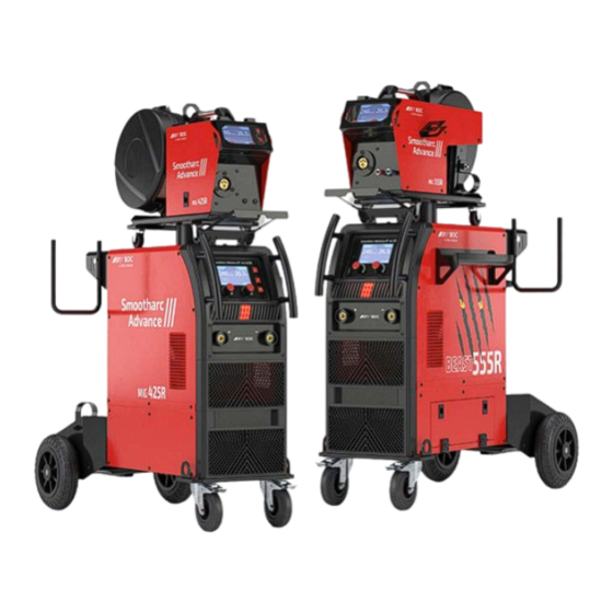
- Page 1 MIG 425R & 555R Operating Manual...
- Page 2 BOC Smootharc Advance III MIG 425R & 555R Operating manual Welcome to a better way of welding. This operating manual provides the basic knowledge required for MIG Welding, as well as highlighting important areas of how to operate the Smootharc ADVANCE machines. With normal use and by following these recommended steps, your Smootharc ADVANCE machine can provide you with years of trouble-free service.
-
Page 3: Table Of Contents
BOC Smootharc Advance III MIG 425R & 555R Operating manual Contents. 1.0 Recommended Safety Guidelines and Precautions 9.0 Warranty Information Health Hazard Information Terms of Warranty Personal Protection Limitations on Warranty Cylinder Safety Warranty Period Electrical shock Warranty Repairs User Responsibility 10.0 MIG Process Switch on to electrical safety 10.1 Introduction to Metal Inert Gas (MIG) -
Page 4: Recommended Safety Guidelines And Precautions
BOC Smootharc Advance III MIG 425R & 555R Operating manual 1.0 Recommended Safety Guidelines and Precautions Diagram and safety explanation Electrical safety alert Welding electrode causing electric shock Fumes and gases coming from welding process Some safety precautions BOC recommends are as follows: Welding arc rays →... -
Page 5: Health Hazard Information
BOC Smootharc Advance III MIG 425R & 555R Operating manual Health Hazard Information stainless steel, nickel, nickel alloys or galvanised steel, further precautions are necessary. The actual process of MIG welding is one that can cause a variety of hazards. →... -
Page 6: Cylinder Safety
BOC Smootharc Advance III MIG 425R & 555R Operating manual Cylinder Safety Cylinder valve hand-wheel Back-plug Bursting disc Back view of typical cylinder valve Operator wearing personal protective equipment (PPE) in safe position Before operating a cylinder valve Ten points about cylinder safety Ensure that the system you are connecting the cylinder into is suitable for the gas and pressure involved. -
Page 7: Electrical Shock
BOC Smootharc Advance III MIG 425R & 555R Operating manual Electrical shock BOC stock a huge range of personal protective equipment. This combined with BOC’s extensive Gas and Gear network ensures fast, reliable service → Never touch ‘live’ electrical parts throughout the South Pacific. -
Page 8: Switch On To Electrical Safety
BOC Smootharc Advance III MIG 425R & 555R Operating manual Switch on to electrical safety for single-phase equipment BOC welding machines are designed and manufactured to conform to IEC 60974 or AS 60974. This Standard not only covers the machine but also the input cable and plug requirements including the size of the plug that should be used. - Page 9 BOC Smootharc Advance III MIG 425R & 555R Operating manual How important is the correct input cable and plug on a welding machine? The size of the plug depends on a formula that to understand input and output currents and to not only uses the maximum current draw but make sure that the input circuit is correctly rated ✓...
-
Page 10: Package Contents
BOC Smootharc Advance III MIG 425R & 555R Operating manual 2.0 Package Contents MIG 425R Package Contents MIG 555R Package Contents ✓ ✓ Power source with 32A input cable Power source with 32A input cable ✓ ✓ Binzel ABIMIG AT355LW MIG torch – 4m Binzel ABIMIG AT455 MIG torch –... -
Page 11: Technical Specifications
BOC Smootharc Advance III MIG 425R & 555R Operating manual 3.0 Technical Specifications Specifications 425R 555R Part No. ADVANCEIII425R ADVANCEIII555R Main Voltage Three Phase AC420V±15% Three Phase AC420V±15% Frequency 50/60Hz 50/60Hz Rated input current (I ) (A) 17.2 13.7 17.8 23.8 19.6 24.1... -
Page 12: Quick Overview
BOC Smootharc Advance III MIG 425R & 555R Operating manual 4.0 Quick Overview Front and back of power source 425R & 555R Positive Output Power Switch Negative Output Wire Feeder Control Line Socket Wire Feeder Power Line Socket Power cable Front and back of wire feeder 425R Front and back of wire feeder 555R MIG Torch Socket... -
Page 13: Installation
BOC Smootharc Advance III MIG 425R & 555R Operating manual 5.0 Installation Installation for MIG/MAG process (air cooled) Installation for self-shielded flux cored arc welding (Air cooled) Installation for Standard MIG/MAG process 1 Connect the gas hose to the regulator and the rear of the machine. Select correct shielding gas for the application. -
Page 14: Installation For Tig Process
BOC Smootharc Advance III MIG 425R & 555R Operating manual Installation for TIG process Installation for MMA process 5.2 Installation for TIG process 5.3 Installation for MMA process 1 Connect the TIG torch power into the negative (–) terminal to be DCEN. 1 Connect the electrode holder to the positive (+) terminal of the machine and fasten it clockwise tightly (DCEP). -
Page 15: Control Panel
BOC Smootharc Advance III MIG 425R & 555R Operating manual 6.0 Control panel Home Screen – Screen showing welding parameters and job mode Ar CO 0.80 16.5 m/min SAVE Main functions Wire Inch Button Gas Test Button Back Button Adjusting Knob - Left Adjusting Knob - Right Name Description... -
Page 16: Home Screen Icons
BOC Smootharc Advance III MIG 425R & 555R Operating manual Display Screen Functionality 6.2 Home Screen Icons 6.3 Welding parameter Icons Icon Description Icon Description Inductance, Range -50 to +50 Welding mode: Including MIG/SYN, MIG/Manual, TIG and MMA. ARC length voltage adjustment (Synergic mode only) Range -50 to +50 Wire feed speed... -
Page 17: Main Settings (Welding Parameters)
BOC Smootharc Advance III MIG 425R & 555R Operating manual 6.4 Main Settings (Welding parameters) In the Home Screen, select the welding mode through the left knob, rotate the right knob, select Main SET, and then press the right to enter this screen. -
Page 18: Second Settings Screen (Level 2 Parameters)
BOC Smootharc Advance III MIG 425R & 555R Operating manual 6.5 Second Settings screen (Level 2 parameters) Please refer to Section 6.8 on following page for a trigger latch NOTE Available in synergic mode only, need to select explanation. ‘Synergic mode’ to access ‘Second Settings’ screen. 2T Screen Note: Only MIG/ SYN mode has Second SET Screen. -
Page 19: Job Screen
BOC Smootharc Advance III MIG 425R & 555R Operating manual 6.6 JOB Screen In the Main SET/Welding screen of MIG mode, long press (5 seconds left knob to pop up SELECT JOB dialog box. As shown in the figure below. Selecting JOB 1. Long press (5 seconds) the left knob to pop up the SELECT JOB dialog box. 2. -
Page 20: Service Screen
BOC Smootharc Advance III MIG 425R & 555R Operating manual Service Screen In the Home Interface, select the MIG/SYN mode through left knob, rotate right knob, select Main SET, and then press right knob to enter the MIG/SYN welding interface. In the MIG/SYN welding interface, long press (5s) right knob to enter the Service Interface, as shown in the figure below. -
Page 21: Gas Test Screen
BOC Smootharc Advance III MIG 425R & 555R Operating manual 6.11 Gas Test Screen 1. Short press the Gas Test Button the system will START gas testing 2. Short press the Gas Test Button again to STOP gas testing. The GAS TEST will be displayed on the LCD screen, and it will flash continuously, as shown in the figure below. -
Page 22: Operating Your Machine
BOC Smootharc Advance III MIG 425R & 555R Operating manual 7.0 Operating your machine Set-up for MIG/MAG process (air cooled) Set-up for self-shielded flux cored arc welding (Air cooled) Operation Instructions for MIG Starting up Setting second parameters Turn the power switch to the ON position. In the Home Screen, turn the Right knob to select Second SET, and then press Right knob to confirm to enter the Second SET Screen. -
Page 23: Inductance
BOC Smootharc Advance III MIG 425R & 555R Operating manual 7.1.1 Inductance 7.1.2 4T/2T Trigger Latch Selection Inductance in welding is the control of current surges during short circuits. On all MIG machines there is no current or wire feed until the trigger on the The wire touches the weld pool 50 to 150 times per second. -
Page 24: Operation Instruction Of Tig
BOC Smootharc Advance III MIG 425R & 555R Operating manual Set-up for TIG process Set-up for MMA process Operation instruction of TIG Operation instruction of MMA Starting up Starting up Turn the power switch to the ON position. Turn the power switch to the ON position. Connections Connections Connect TIG torch to the negative (–) terminal. -
Page 25: Periodic Maintenance & Troubleshooting
BOC Smootharc Advance III MIG 425R & 555R Operating manual 8.0 Periodic Maintenance & Troubleshooting The working environment and amount of use the machine receives should be taken into consideration when planning maintenance frequency of your Smootharc Advance III welder. Preventative maintenance will ensure trouble-free welding and increase the life of the machine and its consumables. -
Page 26: Warranty Information
BOC Smootharc Advance III MIG 425R & 555R Operating manual 9.0 Warranty Information Terms of Warranty Warranty Period The Smootharc ADVANCE III machine has a limited warranty that covers The warranty is valid for 5 years from date of purchase provided the machine manufacturing and material defects only. -
Page 27: Mig Process
BOC Smootharc Advance III MIG 425R & 555R Operating manual 10.0 MIG Process Typical MIG set up Torch Torch trigger Shroud Gas diffuser Contact tip Welding wire Shielding Weld Droplets Weld pool 10.1 Introduction to Metal Inert Gas (MIG) dioxide shielding gas, or using self-shielding flux-cored wire, requiring no shielding gas. - Page 28 BOC Smootharc Advance III MIG 425R & 555R Operating manual Extended self shielded flux cored wire nozzle In terms of gas shielding, there are two different ways in which this may be To bring the welding current back to 250 amps it is necessary to increase the achieved with the FCAW process.
-
Page 29: Introduction To Metal Cored Arc Welding (Mcaw)
BOC Smootharc Advance III MIG 425R & 555R Operating manual Process Schematic Diagram for MIG / FCAW and MCAW Gas hose Continous wire Wire feed unit Power cable Torch conduit Gas cylinder Welding torch Workpiece Earth clamp Power source Return cable If no external gas shield is required, then the flux fill must provide sufficient specific product being used. - Page 30 BOC Smootharc Advance III MIG 425R & 555R Operating manual Schematic of Dip Transfer Short circuit Necking Arc re-ignition Arc established Arc gap shortens Short circuit Time Current (A) Voltage (V) Short circuit cycle Arcing cycle Modes of Metal Transfer Metal-cored wires transfer metal in dip mode at low currents just like solid MIG wires.
-
Page 31: Fundamentals Of Mig, Fcaw And Mcaw
BOC Smootharc Advance III MIG 425R & 555R Operating manual Schematic of Globular Transfer Schematic of Spray Transfer Gas shroud Shielding gas Wire Droplets Weld Splatter Large droplet Workpiece Workpiece 10.4 Fundamentals of MIG, FCAW and MCAW The current flows continuously because of the high voltage maintaining a long arc and short-circuiting cannot take place. - Page 32 BOC Smootharc Advance III MIG 425R & 555R Operating manual Typical Metal Transfer Mode Cast and Helix Globular Spray Transfer Transfer Transfer Process Cast Metal Inert Gas ✓ ✕ ✓ Helix (MIG) Flux Cored ✓ ✓ ✓* (Gas Shielded) Cast – Diameter of the circle Flux Cored ✓...
- Page 33 BOC Smootharc Advance III MIG 425R & 555R Operating manual Selection of the Correct Shielding Gas The selection of the shielding gas has a direct influence on the appearance and quality of the weldbead. The thickness of the material to be welded will determine the type of shielding gas that has to be selected.
-
Page 34: Gas Tungsten Arc Welding (Gtaw/Tig)
BOC Smootharc Advance III MIG 225C & 255C Operating manual 11.0 Gas tungsten arc welding (GTAW/TIG) Schematic of the TIG welding process Collet Shielding gas Tungsten electrode TIG filler rod Weld pool Workpiece 11.1 Introduction The Tungsten Inert Gas, or TIG process, uses the heat generated by an electric arc struck between a non-consumable tungsten electrode and the workpiece to fuse metal in the joint area and produce a molten weld pool. -
Page 35: Process Variables
BOC Smootharc Advance III MIG 225C & 255C Operating manual 11.3 Process variables Process variable Explanation Usage DCEN When direct-current electrode-negative (straight polarity) For a given diameter of tungsten electrode, higher Narrow bead, is used: amperage can be used with straight polarity. Straight deep penetration polarity is used mainly for welding: •... -
Page 36: Shielding Gas Selection
BOC Smootharc Advance III MIG 225C & 255C Operating manual 11.4 Shielding gas selection 11.5 Welding wire selection The following table includes the recommended welding consumable for Material Shielding gas Benefits the most commonly welded materials. Brass Argon Stable arc Base material BOC Consumable Low fume Cobalt-based alloys Argon... -
Page 37: Tungsten Electrode Selection
BOC Smootharc Advance III MIG 225C & 255C Operating manual 11.6 Tungsten electrode selection Thickness Welding Base metal type range Desired results current Electrode type Shielding gas Tungsten performance characteristics Copper alloys, General purpose DCSP 2% Thoriated 75% Argon/ Best stability at medium currents. Good arc Cu-NI alloys and (EW-Th2) 25% Helium... - Page 38 BOC Smootharc Advance III MIG 225C & 255C Operating manual Tungsten electrode tip shapes and current ranges Tungsten tip preparation Thoriated, ceriated, and lanthanated tungsten electrodes do not ball DCSP (EN) or DCRP (EP) ACHP General Purpose as readily as pure or zirconiated tungsten electrodes, and as such are typically used for DCSP welding.
-
Page 39: Welding Techniques
BOC Smootharc Advance III MIG 225C & 255C Operating manual 11.7 Welding techniques 11.8 Torch movement during welding TIG Welding techniques Tungsten Without Filler Rod Tungsten With Filler Rod Welding direction Welding Vertical 75° direction Welding Rod 60–75° Form pool Form pool 75°... -
Page 40: Positioning Torch Tungsten For Various Weld Joints
90° BOC Smootharc Advance III MIG 225C & 255C Operating manual 90° 70° 90° 90° 20° 70° 90° 20° 20° 20° 20° 20° 20° 20° 75° 75° 20° 75° 10° 15° 75° 15° 10° 15° 10° 15° 10° 70° 10° 90°... -
Page 41: Joint Preparation
BOC Smootharc Advance III MIG 225C & 255C Operating manual 11.10 Joint preparation 10° 10° 10° 6-20 6-20 6-20 10° 10° 10° 1.5-3 6-20 0- S 1.5-3 1.5-3 6-20 6-20 0- S 0- S 10° 10° 10° 6-20 1.5-3 1.5-3 1.5-3 0- S 0- S... - Page 42 BOC Smootharc Advance III MIG 225C & 255C Operating manual Condition Result Long arc length Undercut Porosity Wide bead profile Loss of gas Acute angle coverage Oxides Unsymmetrical bead Angular profile mis-alignment Incomplete Mis-alignment penetration Filler rod removed from gas shield Oxides Oxides movement...
-
Page 43: Mma Process
BOC Smootharc Advance III MIG 425R & 555R Operating manual 12.0 MMA Process Schematic of MMA process in operation 12.1 Process 12.2 Welding Machine Manual Metal Arc welding is the process of joining metals where an electric The most important consideration when contemplating the use of arc welding arc is struck between the metal to be welded (parent metal) and a flux- for the first time is the purchase of a suitable welding machine. -
Page 44: Welding Technique
BOC Smootharc Advance III MIG 425R & 555R Operating manual 12.3 Welding Technique operating qualities which appeals to the beginner and experienced operator alike. Successful welding depends on the following factors: Electrodes and Typical Applications → selection of the correct electrode Name Application → s election of the correct size of the electrode for the job Class. - Page 45 BOC Smootharc Advance III MIG 425R & 555R Operating manual Electrode Size current, set on the current range specified. The limits of this range should not normally be exceeded. The size of the electrode is generally dependent on the thickness of the section being welded, and the larger the section the larger the electrode The following table shows the current ranges generally recommended for BOC Smootharc 13.
-
Page 46: Types Of Joints
BOC Smootharc Advance III MIG 425R & 555R Operating manual Layers Weld Beads Butt Welding Electrode Angle for 1st and 2nd Layers Electrode Angle for Subsequent Layers Face Reinforcement Weld Face Layers Weld Beads Layers Weld Beads Root Face Root Gap Electrode Weld Pool Slag... - Page 47 BOC Smootharc Advance III MIG 425R & 555R Operating manual Welding Progression Angle General notes on Butt Welds Double ‘V’ Butt Weld The first run in a prepared butt weld should be deposited with an electrode Used on plate of 12 mm and over in thickness when welding can be applied from both sides.
-
Page 48: Fillet Welds
BOC Smootharc Advance III MIG 425R & 555R Operating manual Convex Fillet Weld Concave Fillet Weld Actual Throat Actual Throat & Effective Throat & Effective Throat Actual Throat Actual Throat Convexity Convexity Concavity Concavity Effective Throat Effective Throat Size Size Lengh Lengh Size... - Page 49 BOC Smootharc Advance III MIG 425R & 555R Operating manual Recommended Electrode Angles for Fillet Welds Recommended Angles for Overhead Fillet Welds 1st Run 2nd Run 55–60° 55–60° 55–60° 55–60° 40° 40° 40° 40° 3rd Run Multi-run Fillet 20–30° 20–30° 20–30°...
-
Page 50: Typical Defects Due To Faulty Technique
BOC Smootharc Advance III MIG 425R & 555R Operating manual Slag Inclusions Undercutting Lack of Fusion Correct selection of electrodes is important for vertical welding. → letting slag run ahead of the arc. In overhead fillet welds, careful attention to technique is necessary to obtain This defect can be prevented by: a sound weld of good profile. - Page 51 BOC Smootharc Advance III MIG 425R & 555R Operating manual Lack of Fusion Lack of fusion is when the weld metal is not fused to the base metal. This can occur between the weld metal and the base metal or between passes in a multiple pass weld.
-
Page 52: Indicative Welding Parameters
BOC Smootharc Advance III MIG 425R & 555R Operating manual 13.0 Indicative Welding Parameters 13.1 Mild Steel Solid Wire Argoshield Light ® Parameters Dip transfer Spray transfer 1 – 1.6 mm 3 mm 6 mm 3 mm 6 mm 8 mm Material thickness Welding position horizontal... -
Page 53: Stainless Steel Solid Wire
BOC Smootharc Advance III MIG 425R & 555R Operating manual 13.3 Stainless Steel Solid Wire Stainshield Light (AU) Stainshield (NZ) ® ® Parameters Dip transfer Spray transfer 1 – 1.6 mm 2 mm 3 mm 6 mm 8 mm 10 mm Material thickness Welding position horizontal... -
Page 54: Correct Application Techniques
BOC Smootharc Advance III MIG 425R & 555R Operating manual 14.0 Correct Application Techniques Electrical stickout Contact Tube Setback Standoff Distance Visible Stickout Arc length Electrical Stickout Gas Nozzle Contact Tube Consumable Electrode Workpiece Correct Application Techniques Flux cored welding with cored wires takes place normally with the drag technique. - Page 55 BOC Smootharc Advance III MIG 425R & 555R Operating manual Electrical stickout Travel speed Short Normal Long Slow Normal Fast Slow Normal Fast Short Normal Long Electrical stickout The electrical stickout is the distance between the end of the contact tip and the end of the wire.
- Page 56 BOC is a trading name of BOC Limited, a Linde company. © BOC Limited 2022. Reproduction without permission is strictly prohibited. Details given in this document are believed to be correct at the time of printing. Whilst proper care has been taken in the preparation, no liability for injury or damage resulting from its improper use can be accepted.
Need help?
Do you have a question about the BOC Smootharc Advance MIG 425R and is the answer not in the manual?
Questions and answers