Table of Contents
Advertisement
Quick Links
Advertisement
Table of Contents

Subscribe to Our Youtube Channel
Related Manuals for Linde BOC RAPTOR 250R MIG


Summary of Contents for Linde BOC RAPTOR 250R MIG
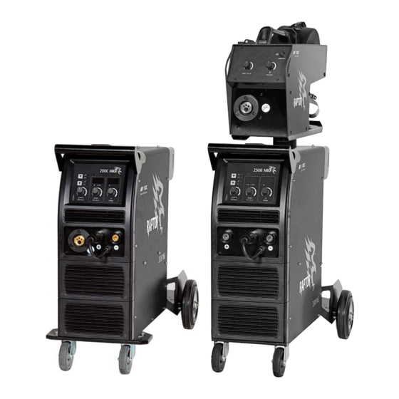
- Page 1 200C MIG, 250R MIG Operating manual...
- Page 2 BOC RAPTOR 200C & 250R MIG Operating manual Welcome to a better way of welding Congratulations on puchasing the Raptor 200C MIG or Raptor 250R MIG welding machine. The products in BOC's range perform with reliability and have the backing of one of South Pacific's leading welding suppliers.
-
Page 3: Table Of Contents
BOC RAPTOR 200C & 250R MIG Operating manual Contents 1.0 Recommended Safety Guidelines 8.0 Troubleshooting and Fault Finding 8.1 200C MIG 2.0 Recommended Safety Precautions 8.2 250R MIG 2.1 Health Hazard Information 9.0 Replacement Parts 2.2 Personal Protection 2.3 Cylinder Safety 10.0 Periodic Maintenance 2.4 Electrical Shock 10.1 Power Source... -
Page 4: Recommended Safety Guidelines
BOC RAPTOR 200C & 250R MIG Operating manual Recommended Safety Guidelines This product is not intended for household or general use. This product is to be used exclusively for commercial or industrial purposes by qualified welders in a workplace where occupational health and safety legislation applies. Some safety precautions BOC recommends are as follows: Repair or replace defective cables immediately. -
Page 5: Recommended Safety Precautions
BOC RAPTOR 200C & 250R MIG Operating manual Recommended Safety Precautions Health Hazard Information and goggles should be provided for others working in the same area. The actual process of welding is one that can cause a variety of hazards. All appropriate safety Recommended filter shades for arc welding equipment should be worn at all times, i.e. -
Page 6: Cylinder Safety
BOC RAPTOR 200C & 250R MIG Operating manual 2.3 Cylinder Safety Cylinder Valve Safety When working with cylinders or operating cylinder valves, ensure that you wear appropriate protective clothing – gloves, Cylinder valve hand-wheel boots and safety glasses. Back-plug Ensure cylinder value is closed before moving or disconnecting equipment. -
Page 7: Electrical Shock
BOC RAPTOR 200C & 250R MIG Operating manual STOP 2.4 Electrical Shock Never touch ‘live’ electrical parts. • Always repair or replace worn or damaged parts. • PLEASE NOTE that under no circumstances should any Disconnect power source before performing any maintenance or •... -
Page 8: Switch On To Electrical Safety
BOC RAPTOR 200C & 250R MIG Operating manual Switch on to electrical safety for single-phase equipment BOC welding machines are designed and manufactured to conform to IEC 60974 or AS 60974. This Standard not only covers the machine but also the input cable and plug requirements including the size of the plug that should be used. - Page 9 BOC RAPTOR 200C & 250R MIG Operating manual How important is the correct input cable, plug and mains power circuit will increase in temperature as well. That’s why it’s important cable and plug on a welding machine? to understand input and output currents and to The size of the plug depends on a formula that ✓...
-
Page 10: Technical Specifications
BOC RAPTOR 200C & 250R MIG Operating manual Technical Specifications 200C MIG 250R MIG Specifications MIG/MAG MIG/MAG Part No. RAPTOR200CMIG RAPTOR250RMIG Power voltage Single phase 230-240 V ±15 % Single phase 230-240 V ±15 % Frequency 50/60 Hz 50/60 Hz Maximum rated input current (I1max) 34 A 29.5 A... -
Page 11: Package Contents & Assembly
BOC RAPTOR 200C & 250R MIG Operating manual Package Contents & Assembly 200C MIG Package Contents 4.2 200C MIG Assembly Instructions Step 1 – Fix the axle to the trolley with M5 screws. ✓ Power source with input cable Step 2 – Fix the wheels to the axle with ferrules and clamp MIG Torch Binzel-style MIG24 torch springs. -
Page 12: 250R Mig Package Contents
BOC RAPTOR 200C & 250R MIG Operating manual 4.3 250R MIG Package Contents ✓ Power source with input cable MIG Torch Binzel-style MIG24 torch ✓ BOC Argon regulator ✓ Work return lead ✓ Wire feeder ✓ Interconnecting cable for wire feeder (10 m) Wire feed rollers Knurled 0.8-0.9/1.0-1.2... - Page 13 BOC RAPTOR 200C & 250R MIG Operating manual...
-
Page 14: Control Panels
BOC RAPTOR 200C & 250R MIG Operating manual Control Panels Control Panel of Raptor 200C MIG Voltage meter Power indicator light 2T/4T button Process selection switch Current meter/ Wire speed meter Inductance Knob Current/Wire speed Knob Voltage Knob Control Panel Features By holding the button down it enables the operator to inch the wire through the torch without having to depress the trigger. -
Page 15: Inductance
BOC RAPTOR 200C & 250R MIG Operating manual Control Panel of Raptor 250R MIG Control panel of wire feeder Voltage meter 17 Wire inch button 9 Power indicator light 1 2T/4T button 2 Process selection switch Current meter/ Wire speed meter 15 Wire speed 3 Inductance Knob adjustment... -
Page 16: Installation & Set-Up For Mig Welding
BOC RAPTOR 200C & 250R MIG Operating manual Installation & Set-up for MIG welding Installation for MIG/MAG process 200C Installation for MIG/MAG process IMPORTANT 1 Connect the gas hose to the regulator and the rear of the machine. Select correct shielding gas for the application. The 200C machine comes fitted with a 15A rated single phase plug for compliance to 2 Insert the earth return lead connection into the front panel. -
Page 17: 200C Mig Welding Set-Up
BOC RAPTOR 200C & 250R MIG Operating manual Front of Raptor 200C MIG Inside of Raptor 200C MIG Wire Inch 1 Voltage 2 Current and Wire feed speed 3 Inductance 4 Positive dinse connector 5 Negative dinse connector 6 Pigtail 7 Process selection switch (MMA, MIG) 6.2 200C MIG Welding Set-up 1 Ensure the machine is correctly plugged into the main circuit... -
Page 18: 250R Mig Welding Setup
BOC RAPTOR 200C & 250R MIG Operating manual Front and back of wire feeder Front and back of power source 1 2T/4T switch 8 Negative terminal 15 Wire speed 2 Process selection 9 Thermal protection/fault indicator 16 MIG torch euro connection 3 Inductance adjustment 10 REM (Remote Equipment Activation) 17 Wire inch... -
Page 19: 250R Installation For Mig/Mag Process
BOC RAPTOR 200C & 250R MIG Operating manual Installation for MIG/MAG proc connector (link plug) to the negative (-) terminal for a DC IMPORTANT electrode negative polarity setting. Primary current rating This machine comes fitted with a 32A rated single phase plug for compliance to AS/NZ electrical regulations. -
Page 20: Installation & Set-Up For Mma Welding
BOC RAPTOR 200C & 250R MIG Operating manual Installation & Set-up for MMA welding Installation for MMA process 200C Installation for MMA process 7.2 200C MMA Welding Set-up 1 Connect an electrode holder [D] to the positive (+) of the 1 Ensure the machine is correctly plugged into the main circuit machine and fasten it clockwise tightly. -
Page 21: 250R Installation For Mma Process
BOC RAPTOR 200C & 250R MIG Operating manual Installation for MMA process 7.3 250R Installation for MMA process 1 Connect the electrode holder to the positive (+) 6 of the machine and fasten it clockwise tightly. 2 Connect the work return lead into the negative (-) 8 of the machine and fasten it clockwise. -
Page 22: Troubleshooting And Fault Finding
BOC RAPTOR 200C & 250R MIG Operating manual Troubleshooting and Fault Finding 200C MIG Problem Possible Cause Solution Press the torch trigger, no wire feed No power Check input power connection. Torch switch is faulty Replace the torch Gas flow out of the torch, no power and no wire Wire feeder current regulator potentiometer Contact authorised service agent feed... - Page 23 BOC RAPTOR 200C & 250R MIG Operating manual 8.2 250R MIG Power source Component Fault symptom Cause Primary cable No or low welding output Bad or incorrect primary connection, lost phase Earth cable and clamp Arc will not initiate Damaged, loose or undersized cables and clamps Connectors and lugs Overheating of connectors and lugs Loose or badly crimped connectors...
-
Page 24: 200C Mig
BOC RAPTOR 200C & 250R MIG Operating manual Replacement Parts Suitability Description Part No. 200C MIG 250R MIG Torch ✓ ✓ Binzel MB EVO PRO 24 3m 012.0371.1 Wire Feed Rollers ✓ ✓ Self-Shielded Flux Cored Knurled 0.8–0.9 ADVANCEKNROL0809 ✓ ✓... -
Page 25: Periodic Maintenance
BOC RAPTOR 200C & 250R MIG Operating manual 10.0 Periodic Maintenance The working environment or amount of use the machine receives should be taken into consideration when planning maintenance frequency of your MIG welder. Preventative maintenance will ensure trouble-free welding and increase the life of the machine and its consumables. -
Page 26: Warranty Information
BOC RAPTOR 200C & 250R MIG Operating manual 11.0 Warranty Information 11.1 Terms of Warranty The Raptor machine has a limited warranty that covers manufacturing and material defects only. The warranty is affected on the day of purchase and does not cover any freight, packaging and insurance costs. -
Page 27: Mig/Mag Welding Process
BOC RAPTOR 200C & 250R MIG Operating manual 12.0 MIG/MAG Welding Process Typical MIG/MAG set up Extended self shielded flux cored wire nozzle Torch Torch trigger Shroud Gas diffuser Contact tip Welding wire Shielding Weld Droplets Weld pool 12.1 Introduction to Metal Inert Gas (MIG) Each gas or gas mixture has specific advantages and limitations. - Page 28 BOC RAPTOR 200C & 250R MIG Operating manual Unlike MIG, which uses a solid consumable filler wire, the wire manufacturers claim for this type of product. Unfortunately in consumable used in FCAW is of tubular construction, an outer many instances the welder has difficulty in utilising this higher wire metal sheath being filled with fluxing agents plus metal powder.
-
Page 29: 123 Introduction To Metal Cored Arc Welding (Mcaw)
BOC RAPTOR 200C & 250R MIG Operating manual Process Schematic Diagram for MIG/MAG, FCAW and MCAW Gas hose Continuous wire Wire feed unit Power cable Torch conduit Gas cylinder Welding torch Workpiece Earth clamp Power source Return cable 123 Introduction to Metal Cored Arc Welding predetermined and accurately controlled speed. -
Page 30: Modes Of Metal Transfer
BOC RAPTOR 200C & 250R MIG Operating manual Schematic of Dip Transfer 1 Short circuit 2 Necking 3 Arc re-ignition 4 Arc established 5 Arc gap shortens 6 Short circuit Time Current (A) Voltage (V) Short circuit cycle Arcing cycle 12.4 Modes of Metal Transfer circuit causes the current to rise and the metal fuses off the end of the electrode. - Page 31 BOC RAPTOR 200C & 250R MIG Operating manual Schematic of Globular Transfer Schematic of Spray Transfer Gas shroud Shielding gas Wire Droplets Weld Splatter Large droplet Workpiece Workpiece currents. Flux-cored wires do not achieve a completely true spray Spray Transfer transfer mode but a transfer mode that is almost true spray may In spray transfer, metal is projected by an electromagnetic force occur at higher currents, and can occur at relatively low currents...
-
Page 32: Fundamentals Of Mig, Fcaw And Mcaw
BOC RAPTOR 200C & 250R MIG Operating manual Typical Metal Transfer Mode Cast and Helix Globular Spray Process Transfer Transfer Transfer Cast Metal Inert Gas (MIG) ✓ ✗ ✓ Metal Active Gas (MAG) Helix Flux Cored (Gas Shielded) ✓ ✓ ✓* Cast –... - Page 33 BOC RAPTOR 200C & 250R MIG Operating manual Selection of the Correct Power Source Power sources for MIG welding is selected on a number of different criteria, including: 1 Maximum output of the machine 2 Duty cycle 3 Output control (voltage selection, wire feed speed control) 4 Portability The following table gives an indication of the operating amperage for different size wires.
-
Page 34: General Welding Information
BOC RAPTOR 200C & 250R MIG Operating manual 13.0 General Welding Information 13.1 Recommended Welding Parameters Argoshield® Light [Mild Steel Solid Wire] Indicative Welding Parameters Dip Transfer Material thickness (mm) 1–1.6 Wire diameter (mm) 0.8–0.9 0.8–0.9 0.8–0.9 0.9–1.0 Voltage (volts) 14–16 16–17 16–18 16–18... - Page 35 BOC RAPTOR 200C & 250R MIG Operating manual Argon [Aluminium Solid Wire] Indicative Welding Parameters Solid Wire Material thickness (mm) Welding position Horizontal Horizontal Horizontal Wire diameter (mm) Current (amps) 160–180 210–220 215–225 Voltage (volts) 21–23 22–24 22.5–24.5 Wire feed speed (m/min) 8.0–9.0 10.0–10.6 10.2–10.8...
-
Page 36: Correct Application Techniques
BOC RAPTOR 200C & 250R MIG Operating manual 14.0 Correct Application Techniques Electrical stickout Contact Tube Setback Standoff Distance Visible Stickout Arc length Electrical Stickout Gas Nozzle Contact Tube Consumable Electrode Workpiece Correct Application Techniques Torch positioned at a drag angle of 10° narrow bead with excessive reinforcement. - Page 37 BOC RAPTOR 200C & 250R MIG Operating manual Electrical stickout Travel speed Short Normal Long Slow Normal Fast Slow Normal Fast Short Normal Long When welding fillet welds the torch should be positioned at an angle of 45° from the bottom plate with the wire pointing into the fillet corner.
-
Page 38: Mma Process
BOC RAPTOR 200C & 250R MIG Operating manual 15.0 MMA Process Schematic of MMA process in operation 15.1 Process 15.2 Welding Machine Manual Metal Arc welding is the process of joining metals where The most important consideration when contemplating the use an electric arc is struck between the metal to be welded (parent of arc welding for the first time is the purchase of a suitable metal) and a flux-coated filler wire (the electrode). -
Page 39: Welding Technique
BOC RAPTOR 200C & 250R MIG Operating manual BOC stocks a huge range of personal protective equipment. This Electrodes and Typical Applications combined with BOC’s extensive network ensures fast reliable Name Application service throughout the South Pacific. Class. BOC Smootharc 18 E7018-1 A premium quality all positional hydrogen controlled electrode for 15.3 Welding Technique... -
Page 40: Types Of Joints
BOC RAPTOR 200C & 250R MIG Operating manual The following table shows the current ranges generally The method of preparation of components to be welded will recommended for BOC Smootharc 13. depend on equipment available and relative costs. Methods may include sawing, punching, shearing, lathe cut-offs, flame cutting Generally Recommended Current Range for BOC Smootharc 13 and others. - Page 41 BOC RAPTOR 200C & 250R MIG Operating manual Layers Weld Beads Butt Welding Electrode Angle for 1st and 2nd Layers Electrode Angle for Subsequent Layers Face Reinforcement Weld Face Layers Weld Beads Layers Weld Beads Root Face Root Gap Electrode Weld Pool General notes on Butt Welds Slag...
-
Page 42: Fillet Welds
BOC RAPTOR 200C & 250R MIG Operating manual Welding Progression Angle 15.6 Fillet Welds The members are fitted as shown, leaving a ‘V’-shaped groove in which a fillet weld is deposited. Fusion should be A fillet weld is approximately triangular in section, joining two complete for the full thickness of the metal. - Page 43 BOC RAPTOR 200C & 250R MIG Operating manual Convex Fillet Weld Concave Fillet Weld Actual Throat Actual Throat & Effective Throat & Effective Throat Actual Throat Actual Throat Convexity Convexity Concavity Concavity Effective Throat Effective Throat Size Size Lengh Lengh Size Size Theoretical Throat...
-
Page 44: Typical Defects Due To Faulty Technique
BOC RAPTOR 200C & 250R MIG Operating manual Recommended Electrode Angles for Fillet Welds Recommended Angles for Overhead Fillet Welds 1st Run 2nd Run 55–60° 55–60° 55–60° 55–60° 40° 40° 40° 40° 3rd Run Multi-run Fillet 20–30° 20–30° 20–30° 20–30° for vertical down welding. All strength joints in vertical plates 10.0 Defects caused by welding technique mm thick or more should be welded using the upward technique. - Page 45 BOC RAPTOR 200C & 250R MIG Operating manual Slag Inclusions Undercutting Lack of Fusion choosing the proper welding current for the type and size of • electrode and the welding position holding the arc as short as possible • pausing at each side of the weld bead when a weaving •...
- Page 46 BOC RAPTOR 200C & 250R MIG Operating manual...
- Page 48 BOC is a trading name of BOC Limited, a Linde company. © BOC Limited 2023. Reproduction without permission is strictly prohibited. Details given in this document are believed to be correct at the time of printing. Whilst proper care has been taken in the preparation, no liability for injury or damage resulting from its improper use can be accepted.
Need help?
Do you have a question about the BOC RAPTOR 250R MIG and is the answer not in the manual?
Questions and answers