Table of Contents
Advertisement
Advertisement
Table of Contents

Related Manuals for Linde BOC Raptor 200C MIG


Summary of Contents for Linde BOC Raptor 200C MIG
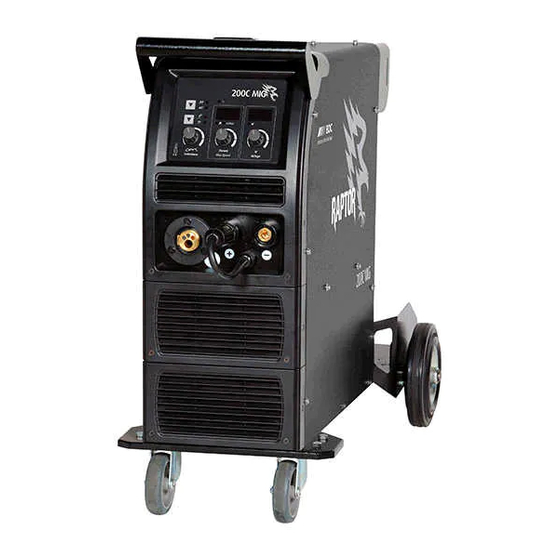
- Page 1 200C MIG Operating Manual...
- Page 2 Welcome to a better way of welding Congratulations on puchasing the Raptor 200C MIG welding machine. The products in BOC's range perform with reliability and have the backing of one of South Pacific's leading welding suppliers. This operating manual provides the basic knowledge required for MIG welding, as well as highlighting important areas of how to operate the Raptor machine.
-
Page 3: Table Of Contents
Contents Recommended Safety Guidelines 8.0 MIG/MAG Welding Process 8.1 Introduction to Metal Inert Gas (MIG) 2.0 Recommended Safety Precautions & Metal Active Gas (MAG) 2.1 Health Hazard Information 8.2 Introduction to Flux Cored Arc 2.2 Personal Protection Welding (FCAW) 2.3 Electrical Shock 8.3 Introduction to Metal Cored Arc Welding (MCAW) 2.4 User Responsibility... -
Page 4: Recommended Safety Guidelines
1.0 Recommended Safety Guidelines Some safety precautions BOC recommends are as follows: Repair or replace defective cables immediately. Keep fire extinguishing equipment at a handy • • location in the shop. Never watch the arc except through • lenses of the correct shade. Keep primary terminals and live parts effectively •... -
Page 5: Recommended Safety Precautions
2.0 Recommended Safety Precautions Health Hazard Information Wear a respirator when natural or forced • ventilation is not good enough. The actual process of welding is one that Eye protection can cause a variety of hazards. All appropriate safety equipment should be worn at all times, i.e. A welding helmet with the appropriate welding headwear, respiratory, hand and body protection. -
Page 6: Electrical Shock
STOP 2.3 Electrical Shock Never touch ‘live’ electrical parts. • Always repair or replace worn or damaged parts. • PLEASE NOTE that under no circumstances should Disconnect power source before performing any • any equipment or parts be altered or changed in maintenance or service. -
Page 7: Switch On To Electrical Safety
Switch on to electrical safety for single-phase equipment BOC welding machines are designed and manufactured to conform to IEC 60974 or AS 60974. This Standard not only covers the machine but also the input cable and plug requirements including the size of the plug that should be used. - Page 8 How important is the correct input cable and plug on a welding machine? The size of the plug depends on a formula that ✓ Use the correct input current, ✓ cable and not only uses the maximum current draw but ✓...
- Page 9 DON‘T ✖ Don’t risk damage to your machine or cause tripping and/or fire by using the wrong input current, cable or plug. ✖ Don’t tamper with plugs or file down earth pins. Doing so will void warranty. Check the rating plate on your machine. Example of BOC rating plate All welding machines that comply with IEC 60974 or AS 60974 must have a rating plate similar to the one shown.
-
Page 10: Package Contents & Assembly
3.0 Package Contents & Assembly Raptor 200C MIG Package Contents 3.2 Assembly Instructions Step 1 – Fix the axle to the trolley with M5 screws. ✓ Power source with input cable Step 2 – Fix the wheels to the axle with ferrules MIG Torch Binzel MB 24KD and clamp springs. - Page 11 Step 1 Step 4 Step 2 Step 3...
-
Page 12: Control Panel
4.0 Control Panel Control Panel of Raptor 200C MIG Voltage meter Power indicator light 2T/4T button Process selection switch Current meter/ Wire speed meter Inductance Knob Current/Wire speed Knob Voltage Knob Controls operator to inch the wire through the torch without having to depress the trigger. -
Page 13: 2T Trigger Latch Selection
The higher the wire feed speed the higher the Therefore, on a heavier plate where more heat is amperage of the machine. required to ensure good fusion, more inductance would contribute immensely. Conversely on thinner Inductance sections less inductance would lead to a decrease Refer to section 9.2 for a complete explanation of in “arc-on”... -
Page 14: Installation & Set-Up For Mig Welding
5.0 Installation & Set-up for MIG welding Installation for MIG/MAG process IMPORTANT The 200C machine comes fitted with a 15A rated single phase plug for compliance to AS/NZ electrical regulations. Installation for MIG/MAG process quality and cause wire feed components to wear rapidly. -
Page 15: Mig Welding Set-Up
Front of Raptor 200C MIG Inside of Raptor 200C MIG Wir e Inc h 1 Voltage 2 Current and Wire feed speed 3 Inductance 4 Positive dinse connector 5 Negative dinse connector 6 Pigtail 7 Process selection switch (MMA, MIG) 5.2 MIG Welding Set-up 9 Inductance can be changed by adjusting the inductance knob (3) on the power source... -
Page 16: Installation & Set-Up For Mma Welding
6.0 Installation & Set-up for MMA welding Installation for MMA process Installation for MMA process 6.2 MMA Welding Set-up 1 Connect the electrode holder [D] to the positive 1 Ensure the machine is correctly plugged into (+) of the machine and fasten it clockwise the main circuit tightly. -
Page 17: Machine Specifications
7.0 Machine Specifications 200C MIG Specifications MIG/MAG Part No. RAPTOR200CMIG Power voltage Single phase 240 V ±15 % Frequency 50/60 Hz Rated input current (Ieff) 14.5 A 14.8 A Output current 50 A to 200 A 50 A to 160 A Output Voltage 16.5 V to 24 V 22 V to 26.4 V... -
Page 18: Mig/Mag Welding Process
8.0 MIG/MAG Welding Process Typical MIG/MAG set up Extended self shielded flux cored wire nozzle Torch Torch trigger Shroud Gas diffuser Contact tip Welding wire Shielding Weld Droplets Weld pool This application combines the advantages of Introduction to Metal Inert Gas (MIG) continuity, speed, comparative freedom from &... -
Page 19: Introduction To Flux Cored Arc Welding (Fcaw)
8.2 Introduction to Flux Cored Arc In terms of gas shielding, there are two different ways in which this may be achieved with the FCAW Welding (FCAW) process. How it Works Additional gas-shielding supplied from an • external source, such as a gas cylinder Flux-cored arc welding (FCAW) uses the heat generated by a DC electric arc to fuse the metal Production of a shielding gas by decomposition... - Page 20 of Ohms Law that states that as the electrical Self-shielded Operation resistance increases if the voltage remains stable There are also self-shielded consumables designed then the current must fall. to operate without an additional gas shield. In this type of product, arc shielding is provided by gases To bring the welding current back to 250 amps generated by decomposition of some constituents it is necessary to increase the wire feed speed,...
-
Page 21: Introduction To Metal Cored Arc Welding (Mcaw)
Process Schematic Diagram for MIG/MAG, FCAW and MCAW Gas hose Continuous wire Wire feed unit Power cable Torch conduit Gas cylinder Welding torch Workpiece Earth clamp Power source Return cable 8.3 Introduction to Metal Cored Arc product being used, some wires designed to run on electrode positive, others preferring electrode Welding (MCAW) negative, and some which will run on either. -
Page 22: Modes Of Metal Transfer
Schematic of Dip Transfer 1 Short circuit 2 Necking 3 Arc re-ignition 4 Arc established 5 Arc gap shortens 6 Short circuit Time Current (A) Voltage (V) Short circuit cycle Arcing cycle MCAW consumables always require an auxiliary 8.4 Modes of metal transfer gas shield in the same way that solid MIG/MAG The mode or type of metal transfer in MIG/MAG wires do. - Page 23 Schematic of Globular Transfer Schematic of Spray Transfer Gas shroud Shielding gas Wire Droplets Weld Splatter Large droplet Workpiece Workpiece Metal-cored wires transfer metal in dip mode at Dip Transfer low currents just like solid MIG/MAG wires. This Also known as short-circuiting arc or short-arc, this transfer mode is used for all positional work with is an all-positional process, using low heat input.
- Page 24 Basic flux-cored wires tend to operate in a globular flows as a stream of smaller droplet into the weld mode or in a globular-spray transfer mode where pool. This effect seems to give much better transfer larger than normal spray droplets are propelled of alloying elements into the weld.
-
Page 25: Fundamentals Of Mig/Mag, Fcaw And Mcaw
Typical Metal Transfer Mode Process Dip Transfer Globular Transfer Spray Transfer Metal Inert Gas (MIG) ✓ ✗ ✓ Metal Active Gas (MAG) Flux Cored (Gas Shielded) ✓ ✓ ✓* Flux Cored (Self Shielded) ✓ ✓ ✗ Metal Cored ✓ ✗ ✓... - Page 26 Cast and Helix Cast Helix Cast – Diameter of the circle Helix – Vertical height A simple test for checking the surface condition Wire Size Amperage Range (A) is to run the wire through a cloth that has been 0.8 mm 60–180 dampened with acetone for 20 secs.
-
Page 27: 2T Trigger Latch Selection
Different grades of shielding are required for 8.6 4T/2T Trigger Latch Selection materials such as stainless steel, aluminium On all MIG machines there is no current or wire and copper. feed until the trigger on the torch is depressed. If a The following table gives an indication of the welder is doing a lot of welding then he has to hold most common shielding gases used for Carbon... -
Page 28: Recommended Welding Parameters For Mig/Mag
8.7 Recommended Welding Parameters for MIG/MAG Argoshield Light Indicative Spray Welding Parameters Dip Transfer Transfer Material thickness (mm) 1–1.6 Welding position Horizontal / Horizontal / Horizontal / Horizontal / Horizontal Vertical Vertical Vertical Vertical Wire diameter (mm) 0.8–0.9 0.8–0.9 0.8–0.9 0.9–1.0 Current (amps) 45–80 60–100 80–120... -
Page 29: Correct Application Techniques
8.8 Correct Application Techniques Flux cored welding with cored wires takes place normally with the drag technique. The welding Direction of welding. torch is tilted at an angle of 10° away from the direction of welding. For all other applications the MIG/MAG welding with solid wires takes place torch angle remains the same. - Page 30 Electrical stickout Contact Tube Setback Standoff Distance Visible Stickout Arc length Electrical Stickout Gas Nozzle Contact Tube Consumable Electrode Workpiece Torch position for fillet welds Electrical stickout When welding fillet welds the torch should be positioned at an angle of 45° from the bottom Short Normal Long...
-
Page 31: Manual Metal Arc Welding Process (Mmaw)
9.0 Manual Metal Arc Welding Process (MMAW) Installation for MMA process TIG Welding techniques Flux Covering Core Wire Weld Metal Slag Weld Pool Workpiece Process voltage in the circuit changes from positive to negative with changes in direction of current flow. Manual Metal Arc welding is the process of joining This complete reversal is called a ‘half cycle’... -
Page 32: Welding Technique
Basic Welding Machine and Cables 9.4 Electrode Selection The choice of welding machine is based mostly on As a general rule the selection of an electrode the following factors: is straight forward, in that it is only a matter of primary voltage, e.g. - Page 33 Electrodes and Typical Applications Name Class. Application A premium quality electrode for general structural and sheet metal work BOC Smootharc 13 E6013 in all positions including vertical down using low carbon steels An iron powder electrode for high speed welding for H-V fillets and flat BOC Smootharc 24 E7024 butt joints.
- Page 34 The limits of this range should not normally be Correct Travel Speed exceeded. The electrode should be moved along in the direction of the joint being welded at a speed that The following table shows the current ranges will give the size of run required. At the same time generally recommended for BOC Smootharc 13.
-
Page 35: Types Of Joints
Butt Welding FACE REINFORCEMENT WELD FACE ROOT FACE ROOT GAP 9.5 Types of Joints Two terms relating to the preparation of butt welds require explanation at this stage. They are: Butt Welds Root Face: the proportion of the prepared edge A butt weld is a weld made between two plates that has not been bevelled. - Page 36 Welding Progression Angle Electrode 70–85˚ Weld Metal Slag Weld Pool Workpiece Direction of Welding Used on thick plates an alternative to a single ‘V’ preparation. It has advantages as regards speed of welding. It takes less weld metal than a single ‘V’, there is less contraction and therefore a lessened tendency to distortion.
-
Page 37: Fillet Welds
Convex Fillet Weld Concave Fillet Weld CONVEXITY ACTUAL THROAT CONVEXITY SIZE ACTUAL THROAT CONCAVITY SIZE LENGH CONCAVITY ACTUAL THROAT LENGH AND EFFECTIVE ACTUAL THROAT SIZE LEG THROAT AND EFFECTIVE EFFECTIVE THROAT SIZE LEG THROAT EFFECTIVE THROAT THEORETICAL THROAT THEORETICAL THROAT THEORETICAL THROAT THEORETICAL THROAT It is necessary to maintain the root gap by tacking... - Page 38 plate it is advisable to entirely remove any ‘false Corner Joints cut’ on the edges prior to welding. Fillet welds are used in the following types of joints: ‘T’ Joints The members are fitted as shown, leaving a ‘V’-shaped groove in which a fillet weld is deposited.
- Page 39 of the weld. A convex fillet weld of specified leg current to achieve maximum penetration at the length has a throat thickness in excess of the root. A short arc length is recommended for fillet effective measurement. welding. The maximum size fillet which should be attempted with one pass of a large electrode is Concave Fillet Weld 8.0 mm.
-
Page 40: Typical Defects Due To Faulty Technique
Recommended Angles for Overhead Fillet Welds 45˚ 15˚ 30˚ of each, so that it has equal leg lengths and the slag inclusions. To produce a weld having good contour of the completed fillet weld penetration and of good profile, a short arc length is slightly convex with no hollows in the face. - Page 41 Defects caused by welding technique Undercutting Slag Inclusions UNDERCUTTING Undercutting is a groove melted in the base metal SLAG INCLUSIONS next to the toe or root of a weld that is not filled by Slag inclusions occur when slag particles are the weld metal.
- Page 42 Lack of Fusion LACK OF FUSION Lack of fusion is when the weld metal is not fused to the base metal. This can occur between the weld metal and the base metal or between passes in a multiple pass weld. Causes of this defect can be: excessive travel speed •...
-
Page 43: Periodic Maintenance
10.0 Periodic Maintenance The working environment or amount of use the machine receives should be taken into consideration when planning maintenance frequency of your RAPTOR 200 MP welder. Preventative maintenance will ensure trouble-free welding and increase the life of the machine and its consumables. -
Page 44: Replacement Parts
11.0 Replacement Parts Suitability Description Part No. Torch Binzel MB EVO PRO 24 3m 012.0371.1 Wire Feed Rollers Self-Shielded Flux Cored Knurled 0.8–0.9 ADVANCEKNROL0809 Aluminium U Groove 0.8–0.9 ADVANCEUROL0809 U Groove 1.0–1.2 ADVANCEUROL1012 Steel, Stainless Steel V Groove 0.6–0.8 ADVANCEVROL0608 V Groove 0.9–1.0 ADVANCEVROL0910... -
Page 45: Troubleshooting And Fault Finding
12.0 Troubleshooting and Fault Finding Problem Possible Cause Solution Press the torch trigger, no wire No power Check input power connection. feed Torch switch is faulty Replace the torch Gas flow out of the torch, no Wire feeder current regulator Contact authorised service agent power and no wire feed potentiometer faulty... -
Page 46: Warranty Information
13.0 Warranty Information 13.1 Terms of Warranty The Raptor machine has a limited warranty that covers manufacturing and material defects only. The warranty is affected on the day of purchase and does not cover any freight, packaging and insurance costs. Verbal promises that do not comply with terms of warranty are not binding 13.3 Warranty Period on warrantor. - Page 48 BOC is a trading name of BOC Limited, a subsidiary of Linde plc. © BOC Limited 2021. Reproduction without permission is strictly prohibited. Details given in this document are believed to be correct at the time of printing. Whilst proper care has been taken in the preparation, no liability for injury or damage resulting from its improper use can be accepted.
Need help?
Do you have a question about the BOC Raptor 200C MIG and is the answer not in the manual?
Questions and answers