Table of Contents
Advertisement
Advertisement
Table of Contents

Related Manuals for Linde BOC RAPTOR 160 MIG


Summary of Contents for Linde BOC RAPTOR 160 MIG
- Page 1 160 MIG Operating Manual...
- Page 2 Welcome to a better way of welding Congratulations on puchasing the Raptor 160 MIG welding machine. The products in BOC's manual MIG range perform with reliability and have the backing of one of South Pacific's leading welding suppliers. This operating manual provides the basic knowledge required for MP welding, as well as highlighting important areas of how to operate the Raptor machine.
-
Page 3: Table Of Contents
Contents Recommended Safety Guidelines 6.0 MIG/MAG Welding Process 6.1 Introduction to Metal Inert Gas (MIG) 2.0 Recommended Safety Precautions & Metal Active Gas (MAG) 2.1 Health Hazard Information 6.2 Introduction to Flux Cored Arc Welding 2.2 Personal Protection (FCAW) 2.3 Cylinder Safety 6.3 Introduction to Metal Cored Arc Welding (MCAW) 2.4 Electrical Shock... -
Page 4: Recommended Safety Guidelines
1.0 Recommended Safety Guidelines Some safety precautions BOC recommends are as follows: Repair or replace defective cables immediately. Keep fire extinguishing equipment at a handy • • location in the shop. Never watch the arc except through • lenses of the correct shade. Keep primary terminals and live parts effectively •... -
Page 5: Recommended Safety Precautions
2.0 Recommended Safety Precautions Health Hazard Information Wear a respirator when natural or forced • ventilation is not good enough. The actual process of welding is one that Eye protection can cause a variety of hazards. All appropriate safety equipment should be worn at all times, i.e. A welding helmet with the appropriate welding headwear, respiratory, hand and body protection. -
Page 6: Cylinder Safety
2.3 Cylinder Safety Cylinder Valve Safety When working with cylinders or operating Cylinder valve hand-wheel cylinder valves, ensure that you wear appropriate protective clothing – gloves, boots and safety Back-plug glasses. Bursting disc Ensure cylinder value is closed before moving or disconnecting equipment. -
Page 7: Electrical Shock
STOP 2.4 Electrical Shock Never touch ‘live’ electrical parts. • Always repair or replace worn or damaged parts. • Disconnect power source before performing any • PLEASE NOTE that under no circumstances should maintenance or service. any equipment or parts be altered or changed in Earth all work materials. -
Page 8: Switch On To Electrical Safety
Switch on to electrical safety for single-phase equipment BOC welding machines are designed and manufactured to conform to IEC 60974 or AS 60974. This Standard not only covers the machine but also the input cable and plug requirements including the size of the plug that should be used. - Page 9 How important is the correct input cable and plug on a welding machine? The size of the plug depends on a formula that ✓ Use the correct input current, ✓ cable and not only uses the maximum current draw but ✓...
- Page 10 DON‘T ✖ Don’t risk damage to your machine or cause tripping and/or fire by using the wrong input current, cable or plug. ✖ Don’t tamper with plugs or file down earth pins. Doing so will void warranty. Always Check the rating plate on your machine. All welding machines that comply with IEC 60974 or AS 60974 must have a rating plate similar to the ✓...
-
Page 11: Package Contents
3.0 Package Contents Package consists of the following: Power source with input cable 2.5m and plug • Binzel-style MB15KD MIG torch 3m • Argon regulator • Work return lead 1.8m • Gas hose with quick release • Wire feed rollers - V Groove 0.6-0.8 •... -
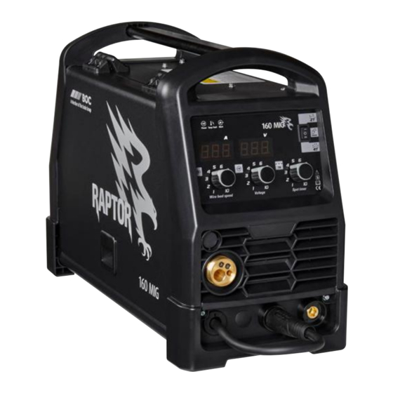
Page 12: Control Panel
3.0 Control panel Front panel of Raptor 160 MIG Function Voltage input (machine is on) Over temperature / fault Amperage output (Machine operating) Wire feed speed Voltage Spot timer 2T / 4T / Spot welding... -
Page 13: Installation
4.0 Installation Installation for MIG/MAG process Polarity change for MIG/MAG process DCEP DCEN 7. Select the correct polarity for the type of Installation for MIG/MAG process wire used as indicated on the consumable 1. Connect the gas hose to the regulator and the packaging. -
Page 14: Machine Specifications
5.0 Machine Specifications BOC RAPTOR 160 MIG Part No. RAPTOR160MIG Input voltage Single phase AC 240V ± 15% Frequency 50 / 60 Hz Rated input plug 10 A Maximum rated input current (I 25 A 1max Maximum effective supply current (I... -
Page 15: Mig/Mag Welding Process
6.0 MIG/MAG Welding Process Typical MIG/MAG set up Extended self shielded flux cored wire nozzle Torch Torch trigger Shroud Gas diffuser Contact tip Welding wire Shielding Weld Droplets Weld pool This application combines the advantages of Introduction to Metal Inert Gas (MIG) continuity, speed, comparative freedom from & Metal Active Gas (MAG) distortion and the reliability of automatic welding... -
Page 16: Introduction To Flux Cored Arc Welding (Fcaw)
6.2 Introduction to Flux Cored Arc In terms of gas shielding, there are two different ways in which this may be achieved with the FCAW Welding (FCAW) process. How it Works Additional gas-shielding supplied from an • external source, such as a gas cylinder Flux-cored arc welding (FCAW) uses the heat generated by a DC electric arc to fuse the metal Production of a shielding gas by decomposition... - Page 17 of Ohms Law that states that as the electrical Self-shielded Operation resistance increases if the voltage remains stable There are also self-shielded consumables designed then the current must fall. to operate without an additional gas shield. In this type of product, arc shielding is provided by gases To bring the welding current back to 250 amps generated by decomposition of some constituents it is necessary to increase the wire feed speed,...
-
Page 18: Introduction To Metal Cored Arc Welding (Mcaw)
Process Schematic Diagram for MIG/MAG, FCAW and MCAW Gas hose Continuous wire Wire feed unit Power cable Torch conduit Gas cylinder Welding torch Workpiece Earth clamp Power source Return cable 6.3 Introduction to Metal Cored Arc product being used, some wires designed to run on electrode positive, others preferring electrode Welding (MCAW) negative, and some which will run on either. - Page 19 Schematic of Dip Transfer 1 Short circuit 2 Necking 3 Arc re-ignition 4 Arc established 5 Arc gap shortens 6 Short circuit Time Current (A) Voltage (V) Short circuit cycle Arcing cycle MCAW consumables always require an auxiliary gas shield in the same way that solid MIG/MAG wires do.
-
Page 20: Modes Of Metal Transfer
Schematic of Globular Transfer Schematic of Spray Transfer Gas shroud Shielding gas Wire Droplets Weld Splatter Large droplet Workpiece Workpiece 6.4 Modes of metal transfer Dip Transfer Also known as short-circuiting arc or short-arc, this The mode or type of metal transfer in MIG/MAG is an all-positional process, using low heat input. - Page 21 Metal-cored wires transfer metal in dip mode at weld pool to spill over, cannot normally be used low currents just like solid MIG/MAG wires. This for positional welding. The main exception is transfer mode is used for all positional work with aluminium and its alloys where, primarily because these types of wire.
-
Page 22: Fundamentals Of Mig/Mag, Fcaw And Mcaw
Typical Metal Transfer Mode Process Dip Transfer Globular Transfer Spray Transfer Metal Inert Gas (MIG) ✓ ✗ ✓ Metal Active Gas (MAG) Flux Cored (Gas Shielded) ✓ ✓ ✓* Flux Cored (Self Shielded) ✓ ✓ ✗ Metal Cored ✓ ✗ ✓... - Page 23 Cast and Helix Cast Helix Cast – Diameter of the circle Helix – Vertical height weldmetal. Solid MIG/MAG wires are all considered residue is found on the cloth the surface of the to be of the 'low Hydrogen type' consumables. wire is not properly cleaned.
-
Page 24: 2T Trigger Latch Selection
Selection of the Correct Polarity on the Power 6.6 4T/2T Trigger Latch Selection Source On all MIG machines there is no current or wire Many power sources are fitted with an optional feed until the trigger on the torch is depressed. If a reverse polarity dinse connector. -
Page 25: Recommended Welding Parameters For Mig/Mag
6.7 Recommended Welding Parameters for MIG/MAG Argoshield Light Indicative Spray Welding Parameters Dip Transfer Transfer Material thickness (mm) 1–1.6 Welding position Horizontal / Horizontal / Horizontal / Horizontal / Horizontal Vertical Vertical Vertical Vertical Wire diameter (mm) 0.8–0.9 0.8–0.9 0.8–0.9 0.9–1.0 Current (amps) 45–80 60–100 80–120... -
Page 26: Correct Application Techniques
6.8 Correct Application Techniques Flux cored welding with cored wires takes place normally with the drag technique. The welding Direction of welding. torch is tilted at an angle of 10° away from the direction of welding. For all other applications the MIG/MAG welding with solid wires takes place torch angle remains the same. - Page 27 Electrical stickout Contact Tube Setback Standoff Distance Visible Stickout Arc length Electrical Stickout Gas Nozzle Contact Tube Consumable Electrode Workpiece Torch position for fillet welds Electrical stickout When welding fillet welds the torch should be positioned at an angle of 45° from the bottom Short Normal Long...
-
Page 28: Periodic Maintenance
7.0 Periodic Maintenance The working environment or amount of use the machine receives should be taken into consideration when planning maintenance frequency of your RAPTOR 160 MIG welder. Preventative maintenance will ensure trouble-free welding and increase the life of the machine and its consumables. -
Page 29: Troubleshooting And Fault Finding
8.0 Troubleshooting and Fault Finding Problem Possible Cause Solution Press the torch trigger, no wire No power Check input power connection. feed Torch switch is faulty Replace the torch Gas flow out of the torch, no Wire feeder current regulator Contact authorised service agent power and no wire feed potentiometer faulty... -
Page 30: Warranty Information
9.0 Warranty Information Terms of Warranty The Raptor machine has a limited warranty that covers manufacturing and material defects only. The warranty is affected on the day of purchase and does not cover any freight, packaging and insurance costs. Verbal promises that do not comply with terms of warranty are not binding 9.3 Warranty Period on warrantor. - Page 32 BOC is a trading name of BOC Limited, a subsidiary of Linde plc. © BOC Limited 2021. Reproduction without permission is strictly prohibited. Details given in this document are believed to be correct at the time of printing. Whilst proper care has been taken in the preparation, no liability for injury or damage resulting from its improper use can be accepted.
Need help?
Do you have a question about the BOC RAPTOR 160 MIG and is the answer not in the manual?
Questions and answers