Circutor Raption 150 Series Instruction Manual
Hide thumbs
Also See for Raption 150 Series:
- Installation manual (64 pages) ,
- Service manual (102 pages)
Table of Contents
Advertisement
Quick Links
Advertisement
Table of Contents

Related Manuals for Circutor Raption 150 Series


Summary of Contents for Circutor Raption 150 Series
- Page 1 Raption 150 Series INSTRUCTION MANUAL (M291B01-03-21A)
- Page 2 Raption 150 Instruction Manual...
-
Page 3: Disclaimer
CIRCUTOR, SA reserves the right to make modifications to the device or the unit specifications set out in this instruction manual without prior notice. CIRCUTOR, SA on its web site, supplies its customers with the latest versions of the device specifica- tions and the most updated manuals. - Page 4 C O P Y R I G H T I N F O R M AT I O N This document is copyrighted, 2021 by CIRCUTOR. All rights are reserved. CIRCUTOR, S.A. reserves the right to make improvements to the products described in this manual at any time without notice.
-
Page 5: Table Of Contents
Raption 150 Here is your manual to use and configure Raption 150 Series Disclaimer ..............................3 Revision log...............................3 Here’s your manual to use and configure Raption 150 Series............5 1.-So,hello!..............................8 2.-Features..............................10 A. Main features..........................10 B. Overview............................11 C. Dimensions............................12 D. Status Beacon lights........................13 E. - Page 6 Raption 150 I) Tariffs............................67 J) Services............................69 K) Configuration Update........................71 L) Firmware.............................72 5.- Teltonika RUT 240..........................74 A. Introduction............................74 B. Teltonika RUT240 configuration....................75 6.-OCPP 1.5.............................90 A. Introduction............................90 B. Before starting..........................91 C. Configuration..........................93 D. Checkup............................101 7.-OCPP 1.6............................102 A. Introduction..........................102 B. Before starting..........................103 C. License activation........................105 D.
- Page 7 Raption 150 Instruction Manual...
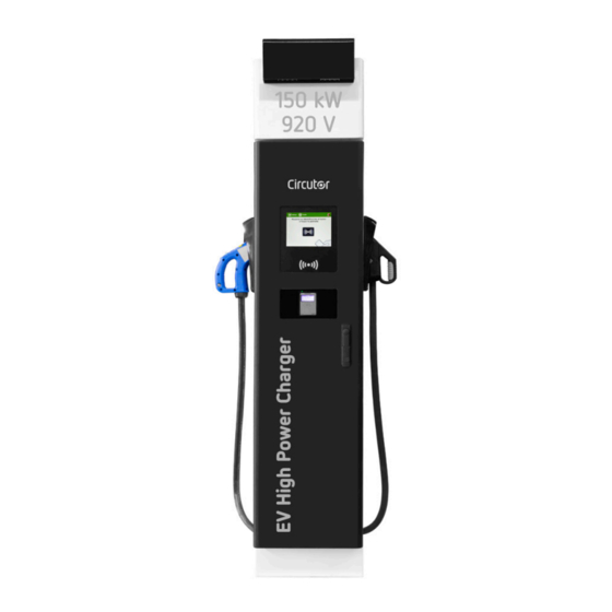
- Page 8 Point and helps the user to perform charging with a high level of efficiency and safety. The CIRCUTOR Charge Point provides a 150kW solution for chargin EVs. Its innovative and original design provides a quick and intuitive way for recharging the electric vehicles, according to the current regulations.
-
Page 9: So,Hello
(broken connectors, caps that • Do not use the Charge Point for don’t close...). anything other than electric vehicle • Use only CIRCUTOR supplied spare charging modes which are defined in IEC 61851-23. parts. • Do not modify the Charge Point. If •... -
Page 10: Features
• Ethernet: the unit allows communicate using TCP / IP on an Ethernet network, giving flexibility to the system operator and management of the Charge Point. • Remote monitoring and control in real-time 3G/4G: it can be done via CIRCUTOR software and also via OCPP integrations through the integrated router. In addition, by using a standard Web browser, you can access to the Charge Point and adjust the settings remotely. -
Page 11: Overview
Raption 150 Features Overview 1.- Cover 2.- Courtesy Lights 3.- Screen 4.- CHA plug 5.- CCS plug 6.- RFID Reader 7.- Locking handle 8.- Front panel 9.- Antenna 10.- CCS/CHA cables 11.- LED beacons Light 12.-Front Door Components can vary depending on the model Instruction Manual... -
Page 12: Dimensions
Raption 150 Dimensions • Units specified in millimeters: Instruction Manual... -
Page 13: Status Beacon Lights
Raption 150 Status Beacon lights Over each connector there is a beacon light, it indicates the state of charge in which the socket/connector is located. Colour Status Description Green Available The connector or socket is available to start a charging session Blue Charging... -
Page 14: Connectors
• Simultaneous, CHAdeMO and CCS 2 connectors at the same time Optionally, Charge Point can be configured to work without simultaneity. It is required a specific configuration file. To obtain the appropriate configuration file please contact CIRCUTOR Post Sales Department. Instruction Manual... - Page 15 Raption 150 DC Connectors Lock If your Charge Point is equipped with the ‘Mechanical connector locking’ accesory at DC holders, is not possible to pull back the connectors from holders without first unlocking it. System consists on a sensor for connector detection and the lock mechanism. CHA connector is locked by the Charge Point;...
- Page 16 Raption 150 The connectors will be delivered right in the moment than the user push over the ‘Connector touching button’ when choose the option in the HMI screen: Instruction Manual...
- Page 17 Raption 150 Instruction Manual...
-
Page 18: How Ti Use It
Raption 150 General The first time the Charge Point is powered on, the system will take around 10 seconds for starting up, the screen will show next image: In the lower right corner, it shows the firmware version. After that 10 seconds have passed, the first screen that appears is the screensaver, Tap over this screen, and the HMI will skip to the next screen: Instruction Manual... - Page 19 Raption 150 How to use it ? At this new screen, the Charge Point is asking for showing the identification card or touch the screen, as you can see there are two options. The first option, showing the identification card, is the option that will let to initiate a ‘Charging session’...
- Page 20 Raption 150 Next screen will appear, press over your language’s flag: This option will allow user to change the language ONLY for the current Charge Transaction. When Charge Point returns to main or standby screen, it will return the default language, which is configured in the Setup Webpage.
-
Page 21: Starting A Charging Session
Raption 150 Starting a charging session Once you have shown your identification card, the HMI will show next screen: Wait while Charge Point performs identification If everything is correct and the user is authorized, the HMI will show next screen: Instruction Manual... - Page 22 Raption 150 Now, the user can choose the connector, always depending of the sort of vehicle that you have and if the connector status is available: At any time is possible to press over this button in order to go back to the “identification screen”.
- Page 23 Raption 150 2- Checking vehicle connection… Please wait In a few seconds, the charging session will start and the HMI will show the charging process. Pressing over this button, the screen will go back to the “identification screen”. Instruction Manual...
-
Page 24: Special Events Starting A Charge
Raption 150 Special events starting a charge A - “Not authorized”: some Charge Points could be working under the supervision of the main management system, called Back Office. It can generate a whitelist in order to register new users, manage charging sessions, etc. If the user is not authorized, the HMI will show the following message: B - “Authorization failed”: if there is some communication problem with the Back Office right at the connecting time:... - Page 25 Raption 150 C - “Not authorized, Concurrent charge”: in this case, the identifier is already involved in another charge transaction: D - “Not authorized, Authorization expired”: is possible that the back office has put a deadline to your identification card and this date is already expired: Instruction Manual...
- Page 26 Raption 150 E - “Not authorized, Authorization blocked”: is possible that the back office has blocked temporarily your identification card. F – After the user has been properly authorized, just at the moment that has to choose the connector, the screen will show the connectors status. It could appear some problem. It is possible to use the connector painted in dark grey but it will be impossible to use any connector with another symbol or light grey, like in the next picture: Instruction Manual...
- Page 27 Raption 150 G - Another issue that can occur is “Vehicle not detected”. Unlock the connector, connect again and press over ‘Retry’ button. H – Almost all vehicles cannot charge if the shift lever is not in parking mode position. This situation can be detected by the Charge Point and it will be displayed by HMI as “Please, check vehicle shift position, put in parking mode”.
- Page 28 Raption 150 I – Is possible that the problem that appears is not a concrete one. The HMI will show next screen, press over ‘Retry’ button. Instruction Manual...
-
Page 29: Stopping A Charging Session
Raption 150 Stopping a charging session The HMI is showing the charging process and next message “Show your identification to stop”, the session can be stopped by the same user that has started it. After showing the identification card, the Charge Point will allow you to stop the charging session by pressing over the ‘Stop’... - Page 30 Raption 150 Once you have stopped the charging session the HMI will show the summary screen,.Press over the ‘Exit’ touch button and disconnect your vehicle: Instruction Manual...
-
Page 31: Charging Information
Raption 150 Charging information Depending of the the connector used, the HMI screen can show different process information. The information is almost the same except for few details. The following images show the basic charging process information. 1 — C H A R G I N G D C 1- Language button: pressing over this button it is possible to change the HMI language. -
Page 32: Charging Summary
Raption 150 Charging summary S U M M A R Y S C R E E N F O R D C ( C C S / C H A M O ) 1- Language button: pressing over this button it is possible to change the HMI language. 2- Process instructions: different instructions can be displayed. -
Page 33: Emergency Button
Raption 150 Emergency button If for any reason the Emergency button is pressed, all in progress charge transactions will be stopped, the beacon lights will turn red and it will not be possible to start new charge transaction until the recovery process is completed successfully. All the power modules will shut down in order to protect the user and the own Charge Point. -
Page 34: Connectors Status
Raption 150 Connectors status The HMI screen shows a different symbols over the connector pictures, as you can see below: It means that the connector is ready to be used. This connector is out of service for any technical reason. Press over ‘Information’... - Page 35 Raption 150 The user cannot use this connector because another user is already using it. This connector has been reserved and only will be able to use per the user that has made the reserve. Note: if the user that has reserved the Charge Point is yourself the charging session will start normally, if not, the Charge Point will not be able to charge until the date and time displayed have expired.
-
Page 36: Consulting The Connectors Status
Raption 150 Consulting the connectors status It is possible to press over each connector picture to get more information about the status: 1 — C O N N E C T O R AVA I L A B L E 2 —... - Page 37 Raption 150 3 — C O N N E C T O R D I S A B L E D 4 — C O N N E C T O R I N U S E Instruction Manual...
- Page 38 Raption 150 5 — C O N N E C T O R R E S E R V E D 6 — C O N N E C T O R B L O C K E D P E R R E S E R V E D *Applies only when simultaneously charge is not available.
- Page 39 Raption 150 7 — C O N N E C T O R B L O C K E D P E R C H A R G I N G *Applies only when simultaneously charge is not available. Instruction Manual...
- Page 40 Raption 150 Errors The Charge Point can report about different sort of errors which can be from different parts or devices. When the ‘Error screen’ appears, the ‘Information’ touch button has to be pressed in order to see the error message, as you can see below: Instruction Manual...
- Page 41 Raption 150 Instruction Manual...
-
Page 42: Introduction
Raption 150 Introduction The Charge Point can be configured and monitored to establish owner preferences or specific setup using integrated Ethernet communication port allocated in HMI screen device (see below).. Once Service PC is configured as bellow procedure and connection is established with the Charge Point, direct access to the main setup page will be allowed. -
Page 43: How To Configure It
Below table shows, hardware and software needed to setup an IP address to the Charge Point. Service PC running Microsoft Windows, at least Windows XP . UTP Cable (Crossover recommended) IPSetup.exe PowerStudio Scada Client http://circutor.com/ In order to get the software needed, you can download it from downloads/ sat@circutor.com or contact with Instruction Manual... -
Page 44: Network Topology
Raption 150 Network topology Connecting the Service PC with Charge Point needs to be done with static IP address and TCP/IP v4 protocol. Next section shows how to do this configuration. Below image shows Ethernet connection topology and the IP addresses used in this guide as example. For Service PC →... -
Page 45: Lan Connection Procedure
Raption 150 LAN connection procedure This section provides a step-by-step guide to connect the Service PC to the Charge Point in order to see real-time status. 1- On the Service PC click over the ‘Network icon’ next to the clock of the taskbar, and click on ‘Open Network and Sharing Center’... - Page 46 Raption 150 3- Right click on ‘Local Area Connection’ and then click on ‘Properties’ 4- Select ‘Internet Protocol Version 4 (TCP/IP)’ option and click on ’Properties’ Instruction Manual...
- Page 47 Raption 150 5- Setup IP address and subnet mask like as shown here below and click ‘OK’ twice to complete the assigning IP address process to the computer. 6- Now execute IPSetup.exe software provided on the Service PC Instruction Manual...
- Page 48 Raption 150 7- Enter the following parameters and click on ‘Configure’ • MAC of the Charge Point (see label on the cover’s screen) • IP address: i.e.(192.168.1.50) • Netmask: i.e. (255.255.255.0) • Gateway: leave default settings. 8- Wait 30 seconds approximately until the process is complete. Instruction Manual...
- Page 49 Raption 150 9- The process will complete when the following message appears, click on ‘OK’ 10- If the message shown is the next one, check the following parameters and click on ‘OK’ • Check IP address entered. • Check the MAC of the device entered. •...
-
Page 50: Setup Webpage
Raption 150 Setup Webpage Setup webpage allows managing network setup, upgrading devices and other options. Once the Service PC is already connected to Charge Point, it is possible to open Setup Webpage throug the IP entered. In the example shown in the previous section, it has been set 192.168.1.50 Open a web browser on the service PC and enter this IP, next image will appear. -
Page 51: A) Dashboard
Raption 150 Dashboard OVERVIEW As a relevant information, the ‘Summary’ shows: Value Description Firmware version Version of the firmware currently installed in the Charge Point MAC Address Identifier of the network card of the Charge Point Instruction Manual... - Page 52 Raption 150 DEVICES STATUS In this section, it can be consulted the status of the devices which are communicating via RS-485. As a relevant information, the ‘Devices Status’ shows: Value Description Device name Name of the devices inside the Charge Point OK: online Status NOT OK: offline...
- Page 53 Raption 150 SYSTEM STATUS The information shown in this section is basically relative to the state of the PC of the Charge Point. It is necessary for the technical service staff but does not show any information regarding to the external connection of the Charge Point or to the charging session. Instruction Manual...
- Page 54 Raption 150 DRIVERS The information shown in this section refers to the drivers that the Charge Point needs in order to recognize the different devices inside the Charge Point, such as the meters, the mode 3, the RFID reader, etc. Instruction Manual...
- Page 55 Raption 150 REPOSITORY SOURCES The information shown in this section is basically related to the internal behavior of the Charge Point. Instruction Manual...
- Page 56 Raption 150 SYSTEM LOGS The logs shown in this section are automatically produced by the Charge Point. It is a detailed list of the charging sessions, system performance or user activities. When Charge Point is powered ON, system begins to register log files. If the Charge Point is restarted these logs are lost and immediately are created new ones.
-
Page 57: B) Network
Raption 150 Network This section provides basic configuration of the network parameters. In the table below there are explained the different sections of 'Network' Value Description Hostname Name of the Charge Point on the network. DHCP Enable or disable the IP address assignment by a DHCP server (router). - Page 58 RA Wireless AirLink LS300 cellular router is connected to the Charge Point. • Circutor SGE-3G/GPRS: select this option only when Circutor SGE- 3G/GPRS cellular router is connected to the Charge Point. • Teltonika RUT240 LTE: select this option only when Teltonika RUT240 LTE cellular router is connected to the Charge Point.
-
Page 59: C) Modem
Raption 150 Modem If password is changed in the modem, it needs to be adjusted in the Charge Point too. Otherwise communication between modem and Charge Point will be lost. Value Description Reset Web Password Charge Point will use default modem password after sav- ing settings when selecting "ON". -
Page 60: D) Security
Raption 150 Security This section provides basic configuration of the security parameters. Once configured, user and password will be required to enter in the Setup Webpage, avoiding unauthorised access. All parameters are disabled from factory settings. Value Description Authentication ON: authentication enabled OFF: authentication disabled User Name Password... -
Page 61: E) Time
Raption 150 Time This section allows setting the time and region time for the Charge Point. Next, we will explain the different sections of the 'Time' Value Description Time Zone Select the regional time for the Charge Point according to the location Time Current date and time of the Charge Point... -
Page 62: F) Locale
Raption 150 Locale In ‘Locale’ section there are two parameters that can be adjusted. Value Description Locale Language can be selected here. However, it is prefered to use the section available in the 'Services' section. Currency Select the currency from your country. Instruction Manual... -
Page 63: G) Integrations
Raption 150 Integrations Clicking over the ‘Integrations’ tab, user will be able to activate OCPP integrations. Note: the integration of the Charge Point needs a separate chapter. In the next chapter number 6 it is explained how to integrate OCPP. Instruction Manual... -
Page 64: H) Charge Point Configuration
Raption 150 Charge Point Configuration This section applies ONLY when the Raption is working as a Master, as a part of our Master-Slave solution. Please, if that is not the case, skip this section. The Charge Point is capable of balancing the available power based on the number of outlets in use. - Page 65 Raption 150 More fields are shown when selecting a ‘Slave charger model’. By clicking the ‘Save’ button, all the configuration inside ‘Slave chargers configuration’ is applied. Before doing so, make sure all fields are properly filled. Consider that Master Charge Point reboots after clicking ‘Save’ button. Do not perform these actions meanwhile a Charge Transaction is active.
- Page 66 Raption 150 Value Description List of Slave Charge Point models. Slave charger model Note: Select it carefully according to the model described on the label. Allows to specify the name of the charger. Charger Name Note: this name only serves as a label, it does not affect the correct operation of the equipment.
-
Page 67: I) Tariffs
Raption 150 Tariffs In this section, it can be adjusted the cost of a charge transaction in the Raption station. These settings are just displayed to inform the customer. It is necessary to work with an integrated system for the payment, such as Kit VISA or OCPP Integrations. - Page 68 Raption 150 There are few parameters that can be adjusted: Value Description Price Limit Maximum cost of the charge transaction Toll fee to charge Price of a new charge transaction. Price perenergy Amount of money to be payed based on the energy delivered to consumed the EV Price...
-
Page 69: J) Services
Raption 150 Services In this section, there can be adjusted many settings related with the Display.. Clicking over the ‘Services’ tab, next image will appear. Value Description Grid Test HMI shows a test screen to check that touch function works prop- erly. - Page 70 Raption 150 Value Description Advertisements *It is possible to customize the Screen saver image by uploading a .zip file. Images interval (s) Period of time before each image swaps to the next. There are a few restrictions regarding to the file that can be uploaded: •...
-
Page 71: K) Configuration Update
Those vary depending on the model of the charger. A window will pop up in order to choose the file, then click on ‘upload’. To obtain the appropriate configuration file, please contact CIRCUTOR Post Sales Department. Instruction Manual... -
Page 72: L) Firmware
Through ‘Firmware’ tab, the Charge Point firmware can be upgraded remotely. A window will pop up in order to choose the file, then click on ‘upload’. To obtain the latest firmware version, please contact CIRCUTOR Post Sales Department. Instruction Manual... - Page 73 Raption 150 Instruction Manual...
-
Page 74: Teltonika Rut 240
Raption 150 Introduction This section describes how to install the SIM card and setting up the modem. The modem that has been installed in Raption series can be two models, Teltonika RUT 240 or Sierra Wireless AirLink LS300. Modem location The modem is installed inside the unit and the antenna is fixed outside, right on the Charge Point’s roof. -
Page 75: Teltonika Rut240 Configuration
Raption 150 Teltonika RUT 240 Teltonika RUT 240 configuration 1 — M O D E M O V E R V I E W The 4G modem installed from factory in the Charge Point is: Teltonika RUT240 This device allows to the Charge Point connects over 4G networks to remotely view or manage the Charge Point status. - Page 76 Raption 150 LAN Ethernet port Signal strength indication LEDs WAN Ethernet port SIM card holder LAN Led indicator WiFi antenna connector WAN Led indicator Reset button Power connector LTE antenna connectors Power LED 2 — C O N N E C T I O N S TAT U S L E D Explanation of connection status LED indication: 1.
- Page 77 Raption 150 3 — S I M C A R D I N S TA L L AT I O N Explanation of SIM card installation: Insert SIM card which was given by your ISP (Internet Service Provider). Correct SIM card orientation is shown in the picture.
- Page 78 Raption 150 4 — L O G G I N G I N After you’re complete with the setting up as described in the section above, you are ready to start logging into your router and start configuring it. This example shows how to connect through WiFi: 4.1.
- Page 79 Raption 150 4.3. Open a web browser and type http:/ /192.168.1.1 . Use the following parameters when prompted for authentication, and then either click Login with your mouse or press the Enter key. User name: admim Password: admin01 If canot access, use ‘Admin001’ You have now successfully logged into the RUT240!, from here on you can configure almost any aspect of your router.
- Page 80 1. If your SIM provider require any authentication ask them about what type, PAP or CHAP, select it on ‘Authentication method’ field and introduce a password and username. 2. If you need to do some custom over the modem configuration, ask the CIRCUTOR PS- Support staff in order to get the Teltonika modem manual.
- Page 81 Raption 150 4.6. In order to know if the connection has been done properly, check next steps: Go to Status → Network → Mobile and pay attention to Data connection state, it has to be Connected Go to Status → Network → WAN and pay attention to IP address, the modem must has found a public IP address Instruction Manual...
- Page 82 Raption 150 Go to Status → Network → LAN→ DHCP Leases and pay attention to IP addresses At ‘DHCP Leases’ check that the modem has detected the automatic IP address and MAC number for both, your Service PC and the Charge Point. NOTES: 1.
- Page 83 Raption 150 4.7. Go to Network → LAN → Static Leases Complete the fields with next information: Hostname - It can be written the name that you want for your Charge Point MAC address - It will be the MAC number found behind the HMI screen, on the label IP address - 192.168.1.50 After filling the fields, push over ‘Save’...
- Page 84 Raption 150 4.8. Hard reset the dispenser. Wait around 10 seconds after powering off the unit before energising it again. 4.9. As modem has been rebooted as well, it is necessary to log in again. Repeat again the points 4.1 and 4.2 explained above: 4.1 - look for modem access point and connect on it.
- Page 85 Raption 150 4.10. Now, go again to Status → Network → LAN → DHCP Leases and confirm that the information written at the point 4.6 has been successfully recorded: Hostname - the name given for Charge Point MAC address - the MAC of the Charge Point IP address - 192.168.1.50 Instruction Manual...
- Page 86 Raption 150 4.11. Go to Network → Firewall → Port Forwarding → New Port Forward Rule Introduce the ports that you can see in the table below. Enable only the ports you are going to use. Port 50000 is the one used by default as a listening port. If you are working with another one, open it instead of 50000:.
- Page 87 Raption 150 4.12. Go to Network → Firewall → Traffic Rules Roll down and look for ‘Enable_HTTP_WAN’ and ‘Enable_HTTPS_WAN’ fields and enable these. Roll down again and push over ‘Save’ button. Instruction Manual...
- Page 88 Raption 150 4.13. For ending with the modem logging is necessary to do a reboot: Go to System → Reboot and push over the ‘Reboot’ tab During the process, the system will show the progress, do not switch off the modem. 4.14.
- Page 89 Raption 150 4.15. It is necessary to check that the Teltonika RUT240 LTE modem option is chosen and DHCP is ON at Charge Point’s setup webpage: Make sure that your Service PC is still connected with the Charge point through wifi, open a web browser and type 192.168.1.50, next screen will appear: DCHP: ON Address Type: Teltonika RUT240 LTE...
-
Page 90: Ocpp 1.5
Charge Point and a Central System. With this open protocol it is possible to connect any Central System with any Charge Point, regardless of the vendor. Follow next steps in order to configure OCPP 1.5 in the CIRCUTOR Charge Points. Instruction Manual... -
Page 91: Before Starting
Raption 150 OCPP 1.5 Before starting Check following steps in order to ensure the correct function of OCPP 1.5: Go to the Setup Webpage → ‘Network’ tab Public Address Manager establishes where the Charge Point must obtain the public IP address in order to send it later to the backend. - Page 92 Raption 150 Go to the Setup Webpage → ‘Integrations’ tab Charge Point supports different versions of OCPP but only one can be enabled at the same time. Go back to setup web page and click on the ‘Integrations’ tab, choose the option selected under ‘Available integrations’...
-
Page 93: Configuration
Raption 150 Configuration Go to the Setup Webpage → ‘Integrations’ tab Once OCPP 1.5 option is selected, a link appears allowing access to the OCPP configuration. Please, click on the link button as shown in the picture: New tabs are opened to show OCPP Settings. It can also be accessed directly typing: http:/ /<IP>:8080/html/setup.html These tabs require a user identification: User: admin... - Page 94 Raption 150 On the OCPP webpage, go to ‘Charge Box’ tab Check Charge Box Identity and the incoming ports according to the backend policies, please contact to the Central System to get the configuration parameters: Value Description Charge Point identifier Public IP timeout Maximum waiting time to obtain the public IP address of the 3G modem OCPP Internal port...
- Page 95 Raption 150 Go to ‘Central system’ tab Allows the Charge Point to know where the central system is hosted to notify all the requests. Check Central System URL according to the backend policies, please contact to the Central System to get the configuration parameters: Value Description ID Tag Endianness...
- Page 96 Raption 150 Go to ‘OCPP Settings’ tab Check OCPP Settings according to the backend policies, please contact to the Central System to get the configuration parameters: Before making any changes read following table and set each option according to your backend provider. Instruction Manual...
- Page 97 Raption 150 Value Description YES: local list of authorized users -> Enabled Use local white-list NO: local list of authorized users -> Disabled LOCAL: ID authorization has first place on the local white-list. If the user does not exist locally, then in second place backend is asked to obtain the authorization.
- Page 98 Raption 150 Value Description YES: Synchronization of date and time -> Enabled. Use OCPP time NO: Synchronization of date and time -> Disabled. synchronization Note: Date and Time is sent from backend on each heartbeat response. YES: Compress messages between Charge point and backend ->...
- Page 99 Raption 150 Value Description YES: Stop existing charge transaction after response from backend (StartTransaction.conf) when user has already involved Stop charge if in another transaction. StartTransaction replies ConcurrentTx NO: Charge transaction does not stops even if backend rejects the user. (StartTransaction.conf) Note: Set this option according to your backend system.
- Page 100 Raption 150 Go to ‘SSL Certificates’ tab When working with a ‘secure’ connections, HTTPS, a certificate from the backoffice (normally a ‘bundle’ file) may be needed to assure proper communication with the charging station. Depending on the case, select the proper option. Most common case is ‘CS Server CA Cerificate’: Then, select the file and upload the certificate: Once done, please do not forget to save changes using ‘Save’...
-
Page 101: Checkup
Raption 150 Checkup After applying new settings, please go to next URL from Charge Point in order to check properly connection from the integration chosen: http:/ /<IP>/services/cpi/log?app=ocpp1.5 Look especially for the following messages: Jan 10 14:55:49 raption user.debug ocpp1.5: Registering CB after boot Jan 10 14:55:49 raption user.info ocpp1.5: Setting heartbeat interval to 300s Jan 10 14:55:49 raption user.info ocpp1.5: Heart-beat interval changed to 300 Jan 10 14:56:09 raption user.debug ocpp1.5: Synchro date: Done... -
Page 102: Ocpp 1.6
Charge Point and a Central System. With this open protocol it is possible to connect any Central System with any Charge Point, regardless of the vendor. Follow next steps in order to configure OCPP 1.6 in the CIRCUTOR Charge Points. Instruction Manual... -
Page 103: Before Starting
Raption 150 OCPP 1.6 Before starting Check following steps in order to ensure the correct function of OCPP 1.6: Go to the Setup Webpage → ‘Network’ tab Public Address Manager establishes where the Charge Point must obtain the public IP address in order to send it later to the backend. - Page 104 Raption 150 Go to the Setup Webpage → ‘Integrations’ tab Charge Point supports different versions of OCPP but only one can be enabled at the same time. Go back to setup web page and click on the ‘Integrations’ tab, choose the option selected under ‘Available integrations’...
-
Page 105: License Activation
License activation If the Charge Point does not have the license applied, the following message pops up: To obtain the license file please contact CIRCUTOR Post Sales Department. The license can be applied by clicking on the ‘Select File’ button. - Page 106 Raption 150 A window will pop up in order to choose the file, then click on ‘upload’. Instruction Manual...
-
Page 107: Configuration
Raption 150 Configuration Go to the Setup Webpage → ‘Integrations’ tab Once OCPP 1.6 option is selected, a link appears allowing access to the OCPP configuration. Please, click on the link button as shown in the picture: New tabs are opened to show OCPP Settings. It can also be accessed directly typing: http:/ /<IP>:8080/html/setup.html These tabs require a user identification: User: admin... - Page 108 Raption 150 On the OCPP webpage, go to ‘Charge Box’ tab Check Charge Box Identity and the incoming ports according to the backend policies, please contact to the Central System to get the configuration parameters: Instruction Manual...
- Page 109 Raption 150 Value Description Charge Point identifier Maximum size of the Authorization Cache, that autonomously main- tains a record of previously presented identifiers that have been suc- Cache max. size cessfully authorized by the Central System. It can be viewed accessing to the following URL: http:/ /<IP>:8080/services/cmd/dump_cache.xml YES: Synchronization of date and time ->...
- Page 110 Raption 150 Go to ‘Central system’ tab Allows the Charge Point to know where the central system is hosted to notify all the requests. Check Central System URL according to the backend policies, please contact to the Central System to get the configuration parameters: Value Description ID Tag Endianness...
- Page 111 Raption 150 Go to ‘OCPP Settings’ tab Check OCPP Settings according to the backend policies, please contact to the Central System to get the configuration parameters: Instruction Manual...
- Page 112 Raption 150 Value Description YES: maintain a local list of all presented identifiers that have been Authorization cache successfully authorized by the Central System. enabled NO: authorization for presented identifiers is requested directly to the Central System YES: the Charge Point asks for authorization when the Central System Authorize remote Tx sends a remote start requests...
- Page 113 Raption 150 Value Description YES: Charge Transaction stops when the cable is disconnected from the EV Stop transaction when EV unplugged NO: Charge Transaction does not stop when the cable is disconnected from the EV; furthermore, if it is reconnected energy transfer is allowed again.
- Page 114 Raption 150 Value Description Number of seconds between MeterValue during an ongoing Charge Metervalue sample Transaction. interval Note: setting this value to 0 disables the MeterValue. Transaction Number of seconds between transaction message attempts. message retry interval Note: setting this value to 0 disables the attempts. Number of seconds the Charge Point must wait for the user to plug/ Charging cable unplug the cable.
- Page 115 Raption 150 Go to ‘SSL Certificates’ tab When working with a ‘secure’ connections, WSS, a certificate from the backoffice (normally a ‘bundle’ file) may be needed to assure proper communication with the charging station. Depending on the case, select the proper option. Most common case is ‘CS Server CA Cerificate’: Then, select the file and upload the certificate: Instruction Manual...
- Page 116 Raption 150 Once done, please do not forget to save changes using ‘Save’ button in the upper right bar: Please, wait until the new configuration is being applied to the Charge Point. A message is displayed informing the progress: Instruction Manual...
-
Page 117: Checkup
Raption 150 Checkup After applying new settings, please go to next URL from Charge Point in order to check properly connection from the integration chosen: http:/ /<IP>/services/cpi/log?app=ocpp1.6 If ‘CB boot notification: success’ appears then Charge Point is properly connected to the back-end. - Page 118 The IP address assigned in the chapter 5, will be useful to connect with the Charge Point in order to monitor the real-time status. The main way to connect is using the PowerStudio client software supplied by CIRCUTOR, and can also be downloaded in the download area of the CIRCUTOR website.
-
Page 119: Monitoring
Raption 150 Monitoring Instruction Manual... -
Page 120: Output Power Setup
Raption 150 Introduction This section shows how to manage the output power delivered by the Charge Point for CCS and CHA. To do this action you have to keep connected through the program PowerStudio client software. Limiting the output power will be useful when the input power supply for the Charge Point is not enough powerful to feed and keep a good level of charge for electric vehicles. -
Page 121: Power Modules Operation
Raption 150 Output power setup Power Modules operation Before apply any adjustment, it is important to understand the way the power of this Charge Point works. There is a total of 12 power modules, divided in two blocks of 6 each one. When there is only one car charging, the two blocks work for the plug in use. -
Page 122: Adjusting The Output Power
Raption 150 Adjusting the output power Steps: 1- Execute PowerStudio Client software 2- Push on ‘General’ tab and after on ‘Connect’ tab Instruction Manual... - Page 123 Raption 150 3- Enter the IP address given to the Charge Point and port number 80, after, press over ‘Ok’ 4- Press on the ‘Views’ tab icon at the TOOLBAR and after click on ‘Devices status’: Instruction Manual...
- Page 124 Raption 150 5- Find in the Serial 1, the CCS-Mode 4 and CHADEMO-Mode 4 options. Click on the connector whose power has to be adjusted, CCS or CHA 6- Once the CCS-Mode 4 is already opened, press over Combo - General 1 and press the setup button.
- Page 125 Raption 150 7- The pop-up window below appears, at ‘Limit Power’ tab it is possible to set the maximum DC power output, it can be selected from 10 kW til 150kW for CCS. Click ‘OK’ to confirm changes. Instruction Manual...
- Page 126 Raption 150 8- Once the CHADEMO-Mode 4 is already opened, press over CHAdeMO - General 1 and press the setup button. Instruction Manual...
- Page 127 Raption 150 9- The pop-up window below appears, at ‘Limit Power’ tab it is possible to set the maximum DC power output, it can be selected from 10 kW til 50 kW for CHA. Click ‘OK’ to confirm changes. Instruction Manual...
- Page 128 Raption 150 ELECTRICAL DATA HC Models HC CCS1 HC CCS2 HC DUO CCS2 CHA HC DUO CCS1 CHA HC DUO CCS1 HC DUO CCS2 Maximum CCS: 150 kW CCS: 150 kW 150 kW 150 kW 150 kW 150 kW Ouput Power CHA: 80 kW CHA: 80 kW Output voltage...
-
Page 129: Technical Data
Raption 150 Technical Data CHARGE POST Network connection Recommended S/FTP Cat5e Interface protocol OCPP 1.5 (1.6 J optional) ISO / IEC14443A / B MIFARE Classic / DESFire EV1 RFID system ISO 18092 / ECMA-340 NFC 13.56MHz Display HMI 8” anti vandal touch screen Power limit control DC by software DC cable lenght CCS... - Page 130 Raption 150 OPTIONAL DEVICES Wireless communication 4G LTE /Wi-Fi Hotspot/GPRS/GSM Surge protection Four pole transient surge protector IEC 61643-1 (class II) Cable Length 5.5 m (all cables) Anti-vandal connector CHAdeMO, CCS (mechanical connector locking) protection Legic Advant / Legic Prime RFID Extension ISO 15693/ISO 18092.
-
Page 131: Need Help
CIRCUTOR guarantees its products against any manufacturing defect for two years after the delivery of the devices. CIRCUTOR will repair or replace any defective factory product returned during the guar- antee period. • No returns will be accepted and no device will be repaired or replaced if it is not accompanied by a report indicating the defect detected or the reason for the return. - Page 132 CIRCUTOR, SA. Vial Sant Jordi, s/n 08232 - Viladecavalls (Barcelona) Tel: (+34) 93 745 29 00 - Fax: (+34) 93 745 29 14 www. circutor.com central@circutor.com...
Need help?
Do you have a question about the Raption 150 Series and is the answer not in the manual?
Questions and answers