
Related Manuals for ABB TLE Series


Summary of Contents for ABB TLE Series
- Page 1 — UPS INSTALLATION GUIDE TLE Series 160 to 500 kVA UL S2B TLE Series 300 - 400 - 500 TLE Series 160 - 200 - 225 - 250...
- Page 2 TLE Series 160 to 500 UL S2B UPS Installation Guide / REV-A Model TLE Series 160 - 200 - 225 - 250 - 300 - 400 - 500 UL S2B Issued by ABB Product Document Department – Quartino - CH Approved by ABB R&D Department –...
- Page 3 UPS. Thank you for choosing ABB! Start-up and commissioning! An ABB Global Services Field Engineer must perform start-up and commissioning of the UPS. Please contact ABB Service Center at least two weeks prior to schedule start-up and commissioning at 1-800-292-3739.
- Page 4 While every care has been taken to ensure the completeness and accuracy of this manual, ABB assumes no responsibility or liability for any losses or damages resulting from the use of the information contained in this document.
-
Page 5: Table Of Contents
4.8.1 TLE Series 160 - 200 - 225 - 250 - Power connection with Common Input Utility ........35 4.8.2 TLE Series 160 - 200 - 225 - 250 - Power connection with Dual Input Utility .......... 37 4.8.3 TLE Series 300 - 400 - 500 - Power connection with Common Input Utility ......... 40 4.8.4 TLE Series 300 - 400 - 500 Power connection with Dual Input Utility ........... -
Page 6: Safety Rules
UPS Installation Guide / REV-A Safety rules Save these instructions! This manual contains important instructions for models TLE Series 160 to 500 that should be followed during installation and maintenance of the UPS and Battery. General Move the UPS in an upright position in its original package to the final destination room. - Page 7 7/62 TLE Series 160 to 500 UL S2B UPS Installation Guide / REV-A Safety instructions when working with Battery Danger! External Battery must be installed and connected to the UPS by Qualified Service Personnel. Installation Personnel must read this entire section before handling the UPS and Battery.
-
Page 8: Safety Symbols And Warnings
8/62 TLE Series 160 to 500 UL S2B UPS Installation Guide / REV-A 1.1 Safety symbols and warnings Safety warnings The text of this manual contains some warnings to avoid risk to the persons and to avoid damages to the UPS system and the supplied critical loads. -
Page 9: Layout
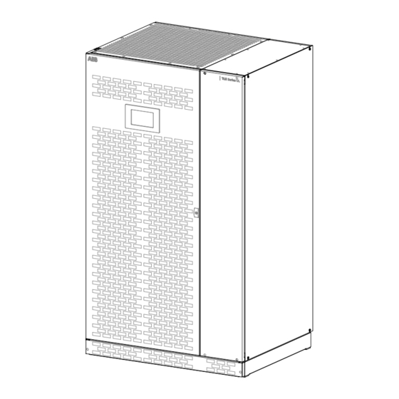
Fig. 2.1-1 TLE Series 160 - 200 - 225 - 250 - General view SNMP Fig. 2.1-4 Connectivity Rack Fig. 2.1-2 TLE Series 160 - 200 - 225 - 250 - General view with open doors Fig. 2.1-5 Q1 - UPS Output switch... - Page 10 TLE Series 160 to 500 UL S2B UPS Installation Guide / REV-A J35 P Fig. 2.1-6 TLE Series 160 - 200 - 225 - 250 - General view without protection panels Opening for top cable entry (*) Opening for bottom cable entry (*)
-
Page 11: Layout Tle Series 300 - 400 - 500
Fig. 2.2-3 Control panel SNMP Fig. 2.2-1 TLE Series 300 – 400 - 500 - General view Fig. 2.2-4 Connectivity Rack Fig. 2.2-2 TLE Series 300 – 400 - 500 - General view with open doors Fig. 2.2-5 Q1 - UPS Output switch... - Page 12 TLE Series 160 to 500 UL S2B UPS Installation Guide / REV-A J35 P Fig. 2.1-6 TLE Series 300 – 400 - 500 - General view without protection panels Opening for top cable entry (*) Opening for bottom cable entry (*)
-
Page 13: Environment
UPS packing materials must be recycled in compliance with all applicable regulations. Recycling at the end of service life! ABB, in compliance with environment protection recommends to the User that the UPS equipment, at the end of its service life, must be recovered conforming to the local applicable regulations. -
Page 14: Installation
14/62 TLE Series 160 to 500 UL S2B UPS Installation Guide / REV-A Installation 4.1 Transport The UPS is packaged on a pallet suitable for handling with a forklift. The UPS must be moved in upright position. Do not tilt cabinets more than +/- 10° during handling. -
Page 15: Dimensions And Weights Tle Series 160 To 500
34.06" 44.10" 865mm 1120 mm Fig. 4.1.1-1 TLE Series 160 - 200 - 225 - 250 - UPS cabinet dimensions TLE Series 300 - 400 - 500 Dimensions and weights 63.78 x 34.06 x 75.00 inches Dimensions (W x D x H) -
Page 16: Delivery
4.2 Delivery When delivered, inspect the package integrity and the physical conditions of the cabinets carefully. In case of any damage sustained during transport, immediately inform the carrier and contact your local ABB Service Center. A detailed report of the damage is necessary for any insurance claim. -
Page 17: Place Of Installation
4.4 Place of installation 4.4.1 UPS location Note! UPS installation and connection must be performed only by an ABB Service Technician! If optional cabinets and accessories are included with the UPS, please refer to those accompanying manuals for installation and operating instructions. - Page 18 Opening for input and output cable connections Utility input Output load Battery Frontal side Fig. 4.4.1-2 TLE Series 160 - 200 - 225 - 250 – Openings on top of the cabinet for input and output cables connections Utility input Output load Battery Frontal side Fig.
- Page 19 Fig. 4.4.1.6 TLE Series 160 to 500 – Fixing of the UPS cabinet on the floor 2.13 " / 54 mm TLES_UL_160-250_S2b_UPS view Bottom_ABB_02a 2.37 " / 60 mm Frontal side 27.56 "...
-
Page 20: Battery Location
UPS 2 UPS 2 UPS 1 UPS 1 Fig. 4.4.1-9 TLE Series 160 - 200 - 225 - 250 Fig. 4.4.1-10 TLE Series 300 - 400 - 500 RPA Parallel System disposition RPA Parallel System disposition In case of RPA Parallel System, try to place the UPS modules in sequence of their numbers (marked on the packing). -
Page 21: Ventilation And Cooling
21/62 TLE Series 160 to 500 UL S2B UPS Installation Guide / REV-A 4.5 Ventilation and cooling Cables Fig. 4.5-1 Installation on plain floor Fig. 4.5-2 Installation on raised floor The heat produced by the UPS is transferred to the environment by its ventilation. -
Page 22: Unpacking
Red color anomaly evidence The package of the TLE Series 160 to 500 is equipped with ShockWatch (indicator for shock) and TiltWatch (indicator for overthrow) on the outside. These devices indicate an eventual shock or overthrow during Fig. - Page 23 PROTECTIVE FOIL Protective foil to remove as indicated in the label TLE Series 160 to 500 is provided with a “Protective Foil”, on the roof and door/front panels, to prevent material from falling into UPS. Warning! It’s mandatory to remove the “Protective Foil”...
-
Page 24: Electrical Wiring
Ensure that the AC and DC external isolators are OFF and locked out to prevent their inadvertent operation. Do not apply power to the equipment prior to the commissioning by an ABB Service Technician. Before any other input connection, connect and check the grounding wire. -
Page 25: Input/Output Over Current Protection And Wire Sizing
25/62 TLE Series 160 to 500 UL S2B UPS Installation Guide / REV-A 4.7.2 Input/output over current protection and wire sizing The cabling of the UPS system has to be sized according to the UPS power rating. Sizing of circuit Breakers, Fuses and cables for Input Utility, output load and Battery must meet the requirements of local and national electrical codes. -
Page 26: Data For Input/Output And Battery Over Current Protection And Wire Sizing
26/62 TLE Series 160 to 500 UL S2B UPS Installation Guide / REV-A 4.7.3 Data for Input/output and Battery over current protection and wire sizing Note! • Please read the safety precautions at the front of this guide carefully, and thoroughly review the Battery manufacturers installation and maintenance manual before connecting the Battery to the UPS. - Page 27 27/62 TLE Series 160 to 500 UL S2B UPS Installation Guide / REV-A Fig. 4.7.3-3 Dual Input Utility Rectifier & Bypass Fig. 4.7.3-4 Common Input Utility Rectifier & Bypass Size of Branch Circuit Over Current Protection - All Models: - "CAUTION - To reduce the risk of fire, only connect...
- Page 28 28/62 TLE Series 160 to 500 UL S2B UPS Installation Guide / REV-A NEC Section 210-20 (a) Table 310-16. Allowable Ampacities of Insulated Conductors Rated O Through 2000 Volts, 140°F Trough 194°F (60°C Trough 90°C) Not More than Three Current-Carrying Conductors in Raceway, Cable, or Earth (Directly Buried), Based on Ambient Temperature of 86°F (30°C).
-
Page 29: Installation Requirements
UPS Installation Guide / REV-A 4.7.4 Installation requirements Typical examples for the connection of the TLE Series 160 to 500. Single UPS with Common Input Utility for Rectifier & Bypass. Single UPS with Common Input Utility for Rectifier & Bypass, 3-wire distribution (3-phase plus ground) Single UPS with Dual Input Utility for Rectifier &... - Page 30 30/62 TLE Series 160 to 500 UL S2B UPS Installation Guide / REV-A UPS RPA Parallel System with Common Input Utility Rectifier & Bypass UPS RPA Parallel System with Common Input Utility Rectifier & Bypass, 3-wire distribution (3-phase plus ground)
- Page 31 31/62 TLE Series 160 to 500 UL S2B UPS Installation Guide / REV-A UPS RPA Parallel System with Dual Input Utility for Rectifier & Bypass (Connect a single input Neutral to Bypass Utility (inside the UPS, common Neutral for Bypass and Rectifier)
-
Page 32: Wiring Connection
• Once the power cables have been connected, re-install the internal safety shields and close the cabinets by re- installing all external panels. TLE Series 160 - 200 - 225 - 250 Access to the bus bars for the cable connections Top entry cables... - Page 33 33/62 TLE Series 160 to 500 UL S2B UPS Installation Guide / REV-A TLE Series 300 - 400 - 500 Access to the bus bars for the cable connections Top entry c Utility input Battery Output load Utility mains / Battery / Output load...
- Page 34 UPS Installation Guide / REV-A TLE Series 300 - 400 – 500 - Connection bus bars configuration for the top cable entry or bottom cable entry The configuration of the TLE Series 300 - 400 - 500 is with top cable entry as standard (see Fig. 4.8-3).
-
Page 35: Tle Series 160 - 200 - 225 - 250 - Power Connection With Common Input Utility
BR1, BR2 and BR3 MUST REMAIN CONNECTED Fig. 4.8.1-1 TLE Series 160 - 200 - 225 - 250 - Power connection with Common Input Utility Power connection cables are connected to bus bars using M10 bolts. The bolts of the connection cables must be tightened with a torque wrench at 355 Lb-in / 40 Nm. - Page 36 36/62 TLE Series 160 to 500 UL S2B UPS Installation Guide / REV-A Note! This UPS is only designed to operate in a wye-configured electrical system with a solidly grounded neutral. The UPS cannot be operated from a mid-point or end-point grounded delta supply source.
-
Page 37: Tle Series 160 - 200 - 225 - 250 - Power Connection With Dual Input Utility
BR1, BR2 and BR3 MUST BE REMOVED Fig. 4.8.2-1 TLE Series 160 - 200 - 225 - 250 - Power connection with Dual Input Utility Power connection cables are connected to bus bars using M10 bolts. The bolts of the connection cables must be tightened with a torque wrench at 355 Lb-in / 40 Nm. - Page 38 38/62 TLE Series 160 to 500 UL S2B UPS Installation Guide / REV-A Note! This UPS is only designed to operate in a wye-configured electrical system with a solidly grounded neutral. The UPS cannot be operated from a mid-point or end-point grounded delta supply source.
- Page 39 39/62 TLE Series 160 to 500 UL S2B UPS Installation Guide / REV-A TLE Series 160 - 200 - 225 - 250 - Installation notices in case of power connection with Dual Input Utility (3x20x1mm / L=220mm) (3x20x1mm / L=220mm)
-
Page 40: Tle Series 300 - 400 - 500 - Power Connection With Common Input Utility
BR1, BR2 and BR3 MUST REMAIN CONNECTED Fig. 4.8.3-1 TLE Series 300 - 400 - 500 - Power connection with Common Input Utility Power connection cables are connected to bus bars using M10 bolts. The bolts of the connection cables must be tightened with a torque wrench at 355 Lb-in / 40 Nm. - Page 41 41/62 TLE Series 160 to 500 UL S2B UPS Installation Guide / REV-A Note! This UPS is only designed to operate in a wye-configured electrical system with a solidly grounded neutral. The UPS cannot be operated from a mid-point or end-point grounded delta supply source.
-
Page 42: Tle Series 300 - 400 - 500 Power Connection With Dual Input Utility
BR1, BR2 and BR3 MUST BE REMOVED Fig. 4.8.4-1 TLE Series 300 - 400 - 500 - Power connection with Dual Input Utility Power connection cables are connected to bus bars using M10 bolts. The bolts of the connection cables must be tightened with a torque wrench at 355 Lb-in / 40 Nm. - Page 43 43/62 TLE Series 160 to 500 UL S2B UPS Installation Guide / REV-A Note! This UPS is only designed to operate in a wye-configured electrical system with a solidly grounded neutral. The UPS cannot be operated from a mid-point or end-point grounded delta supply source.
- Page 44 44/62 TLE Series 160 to 500 UL S2B UPS Installation Guide / REV-A TLE Series 300 -400 - 500 - Installation notices in case of power connection with Dual Input Utility (with top cable entry) Neutral Utility Neutral Load L3-2...
-
Page 45: Use Of Tle Series 160 To 500 In Eboost™ Operation Mode
45/62 TLE Series 160 to 500 UL S2B UPS Installation Guide / REV-A 4.8.5 Use of TLE Series 160 to 500 in eBoost™ Operation Mode Note! For systems intended to be operated in eBoost™ Operation Mode, the installation shall be protected with suitable surge protection devices (SPDs) on the AC bus feeding the UPSs. -
Page 46: Use Of Tle Series 160 To 500 As Frequency Converter
ABB Service Technician only. When the TLE Series 160 to 500 is utilized for different output frequency compared to the input frequency, the Automatic Bypass function is disabled, therefore the Load cannot be transferred to Utility in case of overload, short circuit, or inverter failure. -
Page 47: Rpa Parallel System Connection
UPS Installation Guide / REV-A 4.9 RPA Parallel System connection Warning! This operation must be performed only by an ABB Service Technician before the initial start-up (ensure that the UPS installation is completely powered down). 4.9.1 Power wiring of Parallel Units... -
Page 48: Parallel Control Bus Connection
48/62 TLE Series 160 to 500 UL S2B UPS Installation Guide / REV-A 4.9.2 Parallel Control Bus connection In case of Parallel System, the communication between the units takes place through the Control Bus Cables. Each Parallel Unit contains the two boards “P13/P14 – IM0222 – Bus Interface Board” (mounted on top of the board “P12 –... - Page 49 49/62 TLE Series 160 to 500 UL S2B UPS Installation Guide / REV-A J1B/1 Note! Final units, first and last, of an RPA Parallel System. On the two boards P13/P14 – IM0222 – Bus Interface Board, of J1A/1 the first and last units of a Parallel...
-
Page 50: Control Bus Cable Location
UPS Installation Guide / REV-A 4.9.3 Control bus cable location Warning! This installation must be performed and verified by an ABB Service Technician before the initial start-up. Ensure that the ups installation is completely powered down. Keep SELV cables separated from high voltage cables. - Page 51 J1A/1 J1B/1 J1B/2÷5 UPS 1 J1A/1 3, 4, 5, 6 UPS 2 J1A/2÷5 Fig. 4.9.3-4 TLE Series 160 - 200 - 225 - 250 - Control Bus cable routing and connection UPS 1 UPS 2/3/4/5 J1B/1 J1B/2÷5 J1B/1 J1A/2÷5 J1A/1...
-
Page 52: Epo - Emergency Power Off" Command Connection
Warning! The connection of an emergency button EPO (Emergency Power Off) must be performed only by an ABB Service Technician when the UPS is completely powered down! Note! The reliability of the system depends on this contact NC (Normally Closed)! An Emergency button (Normally Closed voltage-free contact) can be connected on terminals XA / EPO-1, EPO-2. - Page 53 53/62 TLE Series 160 to 500 UL S2B UPS Installation Guide / REV-A Note! To operationalize this function, in case that the UPS was provided with one or more cards “P4 - Customer Interface” (max. 3 - see Chapter 5), there must be on each card the following: - Remove the cable short-circuiting terminals X2 / 1, 2 (see Fig.
-
Page 54: Connectivity Interface
Connectivity rack TLE Series 300 - 400 - 500 Fig. 5-1 TLE Series 160 to 500 - Connectivity rack and Serial port J35µP – RS232 TLE Series 160 to 500 has the following equipment’s: Serial Port J35µP - RS232 (see Section 5.1). -
Page 55: Serial Port J35Μp - Rs232 (Sub D, Female 9 Pin)
J35 P - RS232 TLE Series 300 - 400 - 500 Fig. 5.1-1 TLE Series 160 to 500 - Serial Port J35µP – RS232 Connection of a serial printer From the display panel it is possible to select printing of measurements, alarms and parameters (see User Manual - Section 6.4 –... -
Page 56: Customer Interface Board
56/62 TLE Series 160 to 500 UL S2B UPS Installation Guide / REV-A 5.2 Customer interface board J1 connector– RJ45 8P8C (see Section 5.2.1) Pin 5: TX (out) Pin 6: RX (in) Pin 4: GND X1 terminal block – Output signals on voltage free contacts (see Section 9.2.2) -
Page 57: Connector J1 - Rj45 8P8C
In case different alarms or operating status are required, they can be configured on the same terminals via software from the Control Panel. The configuration can be changed in parameters mode by an ABB Service Technician using the appropriate “Service Code”. -
Page 58: X2 Terminal Block - "Epo - Emergency Power Off
“GENERATOR ON” on X1 / 11, 22. See Fig. 5.2-1 / X1. Since the Parameter for of the reading of the Generator function is “Service Code” protected, call the nearest ABB Service Centre for it's activation. -
Page 59: X1 Terminal Block - Aux External Maintenance Bypass
59/62 TLE Series 160 to 500 UL S2B UPS Installation Guide / REV-A 5.2.6 X1 terminal block - AUX External Maintenance Bypass If the UPS system is equipped with an external Maintenance Bypass Switch, it is possible to connect a NO (Normally Open) voltage-free aux. -
Page 60: Notes
60/62 TLE Series 160 to 500 UL S2B UPS Installation Guide / REV-A Notes 6.1 Notes Form It is recommended to note in this section Notes, with date and short description all the operations performed on the UPS, as: maintenance, components replacement, abnormal situations, etc. - Page 62 — ABB Power Protection SA Via Luserte Sud 9 6572 Quartino Switzerland abb.com/ups © Copyright 2020 ABB. All rights reserved Specifications subject to change without notice...
Need help?
Do you have a question about the TLE Series and is the answer not in the manual?
Questions and answers