
Related Manuals for ABB PowerValue 11 T G2 Series


Summary of Contents for ABB PowerValue 11 T G2 Series
- Page 1 — U S E R M A N UA L PowerValue 11 T G2 6 kVA B / 6 kVA B2 / 6 kVA S 10 kVA B / 10 kVA B2 / 10 kVA S...
-
Page 2: About This Manual
A B B U P S P R O D U C T S A N D S O L U T I O N S — About this manual — Document information File name 04-3628_ABB_OPM_PVA11 6-10kVA-T_G2_EN_REV-E UPS model PowerValue 11 T G2 6-10 kVA B/B2/S Date of issue 06.04.2018 Issued by... -
Page 3: Table Of Contents
C O N T E N T S — Contents Important safety instructions . . . . . . . . . . . . . . . . . . . . . . . . . . . . . . . . . . . . . . . . . . .5 1 .1 Operator precautions . - Page 4 A B B U P S P R O D U C T S A N D S O L U T I O N S Communication . . . . . . . . . . . . . . . . . . . . . . . . . . . . . . . . . . . . . . . . . . . . . . . . . . . 30 5 .1 RS-232 port .
-
Page 5: Important Safety Instructions
CABINET: DANGER OF ELECTRICAL SHOCK. accidental load loss. DANGER HIGH FAULT CURRENTS (LEAKAGE ABB DOES NOT TAKE ANY RESPONSIBILITY FOR CURRENTS). BEFORE CONNECTING THE DAMAGES CAUSED THROUGH INCORRECT USE MAINS ENSURE THAT THE UPS IS EARTHED! DANGER OF THE UPS SYSTEM . -
Page 6: Declaration Of Safety Conformity And Ce Marking
ABB or authorized agent. The serial number is to the local ABB office or agent authorized shown on the nameplate of the product. by ABB. Note the type code and the serial For further information on troubleshooting, number of the equipment before contacting see Chapter 6. -
Page 7: Maintenance
(around three to five THE BATTERY CIRCUIT IS NOT ISOLATED years at 25°C ambient temperature). Contact FROM THE INPUT VOLTAGE. HAZARDOUS your local ABB or an agent authorized by ABB for VOLTAGES MAY OCCUR BETWEEN THE replacements. BATTERY TERMINALS AND THE GROUND. -
Page 8: Ups Disposal And Recycling
A B B U P S P R O D U C T S A N D S O L U T I O N S — 2 .1 UPS disposal and recycling 2 .1 .1 For professional users in the European Union 2 .1 .2 For disposal in countries outside of the European Union THE CROSSED –OUT WHEELED BIN... -
Page 9: Installation
3 I N S TA L L AT I O N — 3 Installation — 3 .1 Delivery, transportation, positioning and storage 3 .1 .1 Receipt of the UPS and visual inspection Examine the UPS for any signs of damage and When receiving the UPS, carefully examine the ensure that the received UPS corresponds to the packing container and the UPS for any signs of... -
Page 10: Site Planning And Positioning
A B B U P S P R O D U C T S A N D S O L U T I O N S — 3 .2 Site planning and positioning 3 .2 .1 Planning before the installation —... - Page 11 3 I N S TA L L AT I O N 3 .2 .3 .2 External battery modules — 03 EBM Connection 1. Install the EBM model (Refer to UPS model — installation as privous described). 04 EBM Connection 2. Connect EBM to UPS with ‘Battery power cable’. FOR EACH UPS MAKE USE OF THE STANDARD MATCHING BATTERY CABINET;...
-
Page 12: General Characteristics
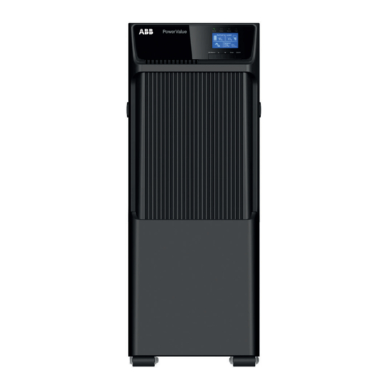
A B B U P S P R O D U C T S A N D S O L U T I O N S — 3 .3 General characteristics 3 .3 .1 UPS 6-10 kVA S — 05 UPS front panel The figures below shows the front and the rear —... -
Page 13: Ups 6-10 Kva B/B2
3 I N S TA L L AT I O N 3 .3 .2 UPS 6-10 kVA B/B2 — 08 UPS front panel The figures below shows the front and the rear — 09 UPS 6 kVA B/B2 panel of the UPS 6-10 kVA B/B2 model. rear panel —... -
Page 14: External Battery Module
A B B U P S P R O D U C T S A N D S O L U T I O N S 3 .3 .3 External battery module — 11 EBM front panel The figures below shows the front and the rear —... -
Page 15: Electrical Installation
BEFORE WORKING ON THIS CIRCUIT, and testing of the UPS, and customer training. CHECK FOR HAZARDOUS VOLTAGE. ABB recommends that an external isolating device is installed between the mains input and DO NOT OPERATE IN CASE OF PRESENCE UPS as shown in Figure 12 to protect against OF WATER OR MOISTURE. -
Page 16: Connections
A B B U P S P R O D U C T S A N D S O L U T I O N S 3 .4 .3 Connections — 15 Terminal connections HIGH LEAKAGE CURRENT: MAKE SURE THAT THE EARTH WIRE IS CONNECTED. -
Page 17: Parallel Installation Operation
3 I N S TA L L AT I O N 3 .4 .4 Parallel installation operation — 16 Parallel system Up to three UPSs can be connected in parallel to installation diagram configure a sharing and redundant output power. From Utility Mains Breaker I/P Breaker... - Page 18 A B B U P S P R O D U C T S A N D S O L U T I O N S How to install a new parallel UPS system: — 5. Connect the input and output wires and make 17 Parallel cable 1.
- Page 19 3 I N S TA L L AT I O N 6. Turn on the input breakers for the parallel UPS. How to remove a single UPS from a parallel system: 7. Hold button for more than 1 s on one UPS in 1.
-
Page 20: Operation
A B B U P S P R O D U C T S A N D S O L U T I O N S — 4 Operation This chapter describes how the UPS is operated through the LCD. The user can: •... -
Page 21: Lcd
4 O P E R AT I O N 4 .1 .3 — Battery status Load/equipment status 21 The default LCD The LCD shows an overview of the status of the UPS: - Input Battery Load - Output - Battery - Load parameters - Working mode Output... -
Page 22: Operating Mode
A B B U P S P R O D U C T S A N D S O L U T I O N S — 4 .2 Operating mode The following table describes the UPS status information: — Table 9: Symbols in operating mode Status Symbol... -
Page 23: Ups Start-Up And Shutdown
4 O P E R AT I O N — 4 .3 UPS start-up and shutdown 4 .3 .2 UPS shutdown SWITCH OFF THE CONNECTED LOADS To shut down the UPS with mains supply: BEFORE TURNING ON THE UPS. SWITCH 1. -
Page 24: Display Functions
A B B U P S P R O D U C T S A N D S O L U T I O N S — 4 .4 Display functions Use the two middle buttons ( ) to When the UPS starts up, the display is in the navigate the menu. -
Page 25: User Settings
4 O P E R AT I O N — 4 .5 User settings The following table displays the options that can be changed by the user. — Table 11: User settings Submenu Available settings Default settings Password Key the password USER Language [English][Deutsch][Español]... -
Page 26: Lcd Operation
A B B U P S P R O D U C T S A N D S O L U T I O N S — 4 .6 LCD operation In addition to the default UPS status summary 4 .6 .2 UPS status menu —... -
Page 27: Measurement Menu
4 O P E R AT I O N 4 .6 .3 Measurement menu 4 .6 .4 Event log menu — 24 Measurement menu By pressing on the Measurement menu, the By pressing on the Event log menu, the next —... -
Page 28: Control Menu
A B B U P S P R O D U C T S A N D S O L U T I O N S 4 .6 .5 Control menu 4 .6 .6 Identification menu — 26 Control menu By pressing on the Control menu, the next By pressing... -
Page 29: Setting Menu
4 O P E R AT I O N 4 .6 .7 Setting menu — Example: set rated output voltage value. 28 Setting menu — 29 Example (set-up) PLEASE CONTACT YOUR LOCAL DISTRIBUTOR FOR FURTHER INFORMATION BEFORE CHANGING SETTINGS. SOME SETTINGS CHANGE THE SPECIFICATION OF THE UPS AND SOME SETTINGS ENABLE OR DISABLE SOME IMPORTANT FUNCTIONS. -
Page 30: Communication
A B B U P S P R O D U C T S A N D S O L U T I O N S — 5 Communication A USB and an RS-232 port are available to enable If there is a power failure and a predicted the communication between the UPS and a shutdown of the UPS due to low battery remote computer/ station. -
Page 31: Usb Port
5 C O M M U N I C AT I O N — 5 .2 USB port The UPS can communicate with USB-compliant computers that run power management software. To establish communication between the UPS and a computer, connect the USB cable to the USB port on the UPS. -
Page 32: Network Management Card (Optional)
A B B U P S P R O D U C T S A N D S O L U T I O N S — 5 .4 Network management card (optional) The PowerValue 11 T G2 is equipped with an To install a network management card: intelligent slot for optional cards for remote 1. -
Page 33: Troubleshooting
6 T R O U B L E S H O OT I N G — 6 Troubleshooting — 6 .1 Fault identification and rectification Alarms and events indicate warnings and notify of errors or potential failures in the system. The output of the UPS is not necessarily affected when an alarm arises but taking the correct actions may prevent loss of power to the load. - Page 34 A B B U P S P R O D U C T S A N D S O L U T I O N S Alarm or Event Possible cause Remedy Battery mode The UPS is powering the equipment with Battery (Orange) LED is on.
- Page 35 6 T R O U B L E S H O OT I N G Alarm or Event Possible cause Remedy BUS Under Voltage Fault (Red) LED is On. Indicates that the UPS has bus undervoltage The UPS transfers to bypass mode if Beep continuous.
-
Page 36: Silencing The Alarm
A B B U P S P R O D U C T S A N D S O L U T I O N S Always have the following information available 4. Mains power condition, load type and when calling the after-sales service department: capacity, environment temperature and 1. -
Page 37: Technical Specifications
7 T E C H N I C A L S P E C I F I C AT I O N S — 7 Technical specifications GENERAL DATA 11T G2 6kVA B/ B2 / S 11T G2 10kVA B/ B2 / S Output rated power 6’000W 10’000W... -
Page 38: Environmental Conditions
A B B U P S P R O D U C T S A N D S O L U T I O N S BATTERY 11T G2 6kVA B 11T G2 6kVA B2 11T G2 6kVA S 11T G2 10kVA B 11T G2 10kVA B2 11T G2 10kVA S AUTONOMY UPS internal... -
Page 39: Appendix A
A P P E N D I X A — Appendix A CS141 SNMP/Modbus card available parameters The parameters available for CS141 SNMP cards (valid for CS141 Basic, CS141 ModBus, CS141 are shown below. Advanced) . Parameter Units Type Available interface Modbus register Measurement Parameters Input Voltage... -
Page 40: Appendix B
A B B U P S P R O D U C T S A N D S O L U T I O N S — Appendix B Winpower SNMP/Modbus card available The parameters available from WinPower parameters (webserver interface) SNMP/Modbus cards are shown below. - Page 41 A P P E N D I X B...
- Page 42 — www.abb.com/ups ups.sales@ch.abb.com © Copyright 2017 ABB. All rights reserved. Specifications subject to change without notice.
Need help?
Do you have a question about the PowerValue 11 T G2 Series and is the answer not in the manual?
Questions and answers