
Related Manuals for Banner LTF


Summary of Contents for Banner LTF
- Page 1 LTF Time of Flight Laser Distance Sensor Instruction Manual Original Instructions p/n: 194135 Rev. J June 22, 2023 © Banner Engineering Corp. All rights reserved.
-
Page 2: Table Of Contents
Wiring Diagrams ......................................9 Connecting to RSD1 ....................................10 Chapter 3 Sensor Programming Quick Menu ....................................... 13 LTF Sensor Menu (MENU) ..................................14 Remote Input ......................................14 Locking and Unlocking the Sensor ................................16 Analog Output Menu (A_OUT) ................................... 17 TEACH 4 mA (0 V) and TEACH 20 mA (10 V) ............................ 17 Midpoint TEACH ... - Page 3 Repeatability Performance ..................................48 Dimensions ........................................ 50 Chapter 7 Troubleshooting ....................51 Chapter 8 Sensor Menu Full Map..................53 Chapter 9 Accessories Cordsets ........................................55 Brackets ........................................56 RSD1 Remote Display....................................57 Chapter 10 Banner Engineering Corp Limited Warranty ............................................. 59 ...
- Page 4 Blank page ...
-
Page 5: Chapter 1 Product Description
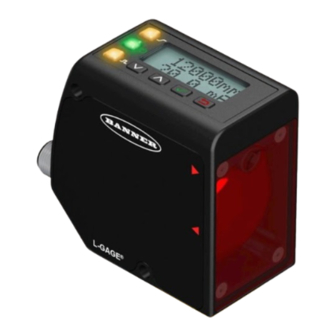
LTF Time Of Flight Laser Distance Sensor Instruction Manual Chapter Contents Models..........................................5 Overview ........................................... 5 Laser Description and Safety Information ................................7 Chapter 1 Product Description Laser distance sensor with both analog and discrete (switched) outputs • High-performance time of flight measurement • Extended ranges up to 24 m • Reliably detects challenging targets • Fast setup with an intuitive interface WARNING: •... -
Page 6: Features And Indicators
LTF Time Of Flight Laser Distance Sensor Instruction Manual See Factory Defaults for a list of sensor default settings. Models with current or voltage analog outputs are available. This manual provides the display information and the navigation paths for the current models with the voltage model text in parentheses if it is different. Features and Indicators Three LED indicators provide an ongoing indication of the ... -
Page 7: Laser Description And Safety Information
LTF Time Of Flight Laser Distance Sensor Instruction Manual Continued from page 6 Enter Button Press Enter to: • Access the Sensor Menu from Run mode • Access the submenus • Move right one digit in distance based settings • Save changes In the Sensor Menu, a checkmark in the lower right corner of the display indicates that pressing En- ter accesses a submenu. Press Enter to save changes. New values flash rapidly and the sensor returns to the parent menu. Escape Button Press Escape to: • Leave the current menu and return to the parent menu • Return to Run mode from the Quick Menu IMPORTANT: Pressing Escape discards any unsaved programming changes. ... - Page 8 LTF Time Of Flight Laser Distance Sensor Instruction Manual For Safe Laser Use - Class 2 Lasers • Do not stare at the laser. • Do not point the laser at a person’s eye. • Mount open laser beam paths either above or below eye level, where practical. • Terminate the beam emitted by the laser product at the end of its useful ...
-
Page 9: Chapter 2 Sensor Installation
LTF Time Of Flight Laser Distance Sensor Instruction Manual Chapter Contents Mount the Device ........................................ 9 Wiring Diagrams ......................................... 9 Connecting to RSD1 ......................................10 Chapter 2 Sensor Installation NOTE: Handle the sensor with care during installation and operation. Sensor windows soiled by finger- prints, dust, water, oil, etc. may create stray light that may degrade the peak performance of the sensor. -
Page 10: Connecting To Rsd1
LTF Time Of Flight Laser Distance Sensor Instruction Manual Connecting to RSD1 The following diagram depicts the connection of the LTF to the optional RSD1 accessory. LTF to RSD1 Double Ended Shielded MQDEC3-503SS MQDEC3-506SS MQDEC3-515SS Double Ended Shielded MQDEC3-530SS MQDEC3-503SS MQDEC3-506SS Flying Lead Shielded MQDEC3-515SS MQDEC2-506 MQDEC3-530SS MQDEC2-515 RSD1 MQDEC2-530 Use these cordsets to connect the RSD1 to the LTF sensor or to other devices, such as PLC inputs, IO-Link masters, or con- trol systems. 5-Pin Male Threaded and 5-Pin Female Quick Disconnect M12 Cordset with Shield—Double Ended ... - Page 11 LTF Time Of Flight Laser Distance Sensor Instruction Manual Continued from page 10 5-Pin Threaded M12 Cordsets with Shield—Single Ended Model Length Style Dimensions Pinout (Female) MQDEC2-506RA 2 m (6.56 ft) 32 Typ. MQDEC2-515RA 5 m (16.4 ft) [1.26"] MQDEC2-530RA 9 m (29.5 ft) 30 Typ. MQDEC2-550RA 15 m (49.2 ft) Right-Angle [1.18"] MQDEC2-575RA 23 m (75.44 ft) M12 x 1 ø...
- Page 12 Blank page ...
-
Page 13: Chapter 3 Sensor Programming
LTF Time Of Flight Laser Distance Sensor Instruction Manual Chapter Contents Quick Menu ........................................13 LTF Sensor Menu (MENU)....................................14 Remote Input ........................................14 Locking and Unlocking the Sensor .................................. 16 Analog Output Menu (A_OUT) ..................................17 Discrete Output Menu (D_OUT)..................................24 Input Menu (INPUT) ......................................34 Measure Menu (MEASURE) ..................................... 35 Display Menu (DISPLAY) ....................................38 Information Menu (INFO) .................................... -
Page 14: Ltf Sensor Menu (Menu)
LTF Time Of Flight Laser Distance Sensor Instruction Manual Quick Menu Map (Window Mode) Quick Menu Mode 4mA Pt (value) set value with 20mA Pt (value) Save setting and return to Quick Menu SPt1 Pt (value) Cancel and return to... - Page 15 LTF Time Of Flight Laser Distance Sensor Instruction Manual Remote Input Map NOTE: Follow procedure for the TEACH/SET method (highlighted in black box) chosen in the TEACH Selection menu. Pulse Timing (T) Mode Timeout is 60 seconds. 0.04 seconds < T < 0.8 seconds Timing between Pulse groups >...
-
Page 16: Locking And Unlocking The Sensor
LTF Time Of Flight Laser Distance Sensor Instruction Manual Remote TEACH window sizes Remote TEACH Window Size (mm) Variable LTF12 LTF24 X1 10 10 X2 20 20 X3 100 100 2000 2000 11950 23950 Locking and Unlocking the Sensor Use the lock and unlock feature to prevent unauthorized or accidental programming changes. A lock symbol displays in the upper left corner of the display to indicate when the sensor is locked. When locked, the menus are available to view settings, but the values cannot be changed. The remote input is also disabled, except for the unlock function. ... -
Page 17: Analog Output Menu (A_Out)
LTF Time Of Flight Laser Distance Sensor Instruction Manual Analog Output Menu (A_OUT) Use the Analog Output menu to view or change: • 4 mA (0 V) setpoint • 20 mA (10 V) setpoint • 12 mA (5 V) window • Slope • Loss of signal behavior Analog Output Menu Map MENU A_OUT A_OUT Tch2Pt Tch2Pt Tch4mA Tch4mA 50mm Tch2Pt Tch20mA Tch20mA 12000mm... - Page 18 LTF Time Of Flight Laser Distance Sensor Instruction Manual Action Result The selected TEACH mode and "Teaching" display while the sensor is being taught. TEACH Accepted Navigate: MENU › A_OUT › Tch2Pt › Tch4mA (Tch0V) The new value is shown on the second line OR of the display and flashes before it is saved and the sensor returns to the parent menu. ...
-
Page 19: Midpoint Teach
LTF Time Of Flight Laser Distance Sensor Instruction Manual Action Result "Tch20mA (Tch10V) Teaching" displays while the sensor is being taught. TEACH Accepted The new value displays on the second line of the display, flashes, and the sensor re- Single-pulse the remote input. turns to Run mode. TEACH Not Accepted ... - Page 20 LTF Time Of Flight Laser Distance Sensor Instruction Manual Continued from page 19 Method Action Result a. Double-pulse the remote input to enter set- a. "REMOTE SETUP" displays. up mode. Remote Input b. "WndSize" and the current window b. Three-pulse the remote input to enter win- size value display. dow size mode. Set the window size.
-
Page 21: Adjust 4 Ma (0 V)
LTF Time Of Flight Laser Distance Sensor Instruction Manual Action Result "Tch12mA (Tch5V) Teaching" displays while the sensor is being taught. TEACH Accepted The new value is shown on the second line of the display and flashes before it is saved and the sensor returns to Navigate: MENU › A_OUT › TchMid › Tch12mA (Tch5V). ... -
Page 22: Adjust 20 Ma (10 V)
LTF Time Of Flight Laser Distance Sensor Instruction Manual Remote Input: Not available Default: 50 mm Adjust 20 mA (10 V) The Adj20mA (Adj10V) option manually adjusts the distance at which the Analog Output is 20 mA (10 V). The value is ad- justable between the sensor's range. It is required to at least maintain the minimum window size. Navigate: MENU › A_OUT › Adj20mA (Adj10V) Remote Input: Not available Default: 12000 mm for LTF12, 24000 mm for LTF24 Slope The Slope option sets the slope as positive or negative. This swaps the 4 mA and 20 mA (0 V and 10 V) values. Navigate: MENU › A_OUT › Slope Remote Input: Available Default: Positive Slope—Current-Sourcing Models Slope—Voltage-Sourcing Models Positive Positive Slope Slope Near Near Window Window Window Window Target Position... -
Page 23: Loss Of Signal
LTF Time Of Flight Laser Distance Sensor Instruction Manual Method Action Result a. The selection flashes rapidly on a. Use Down and Up to change the slope between Positive and Neg- the display. Push Button ative. b. Press Enter to save the selection. b. The selection is saved and the sen- sor returns to "A_OUT Slope". Positive slope: Single-pulse the remote input The selection flashes rapidly on the ... -
Page 24: Discrete Output Menu (D_Out)
LTF Time Of Flight Laser Distance Sensor Instruction Manual Discrete Output Menu (D_OUT) Use this menu to view or change • Setpoints • Midpoint • Mode • Timers • Polarity Discrete Output Menu Map MENU D_OUT D_OUT Tch2Pt Tch2Pt TchSPt1 TchSPt1 50mm... - Page 25 LTF Time Of Flight Laser Distance Sensor Instruction Manual Action Result The target's analog output measurement Present the target. The target must be within the sensor's range.. and distance measurement value display. Access the TEACH mode and TEACH the sensor. Action Result The selected TEACH mode and "Teaching" display while the sensor is being taught.
-
Page 26: Midpoint Teach
LTF Time Of Flight Laser Distance Sensor Instruction Manual Action Result "TchSPt2" and the target's measurement Present the switch point two target. value display. TEACH the sensor. Action Result "TchSPt2 Teaching" displays while the sen- sor is being taught. TEACH Accepted The new value displays on the second line of the display, flashes, and the sensor re- Single-pulse the remote input. ... - Page 27 LTF Time Of Flight Laser Distance Sensor Instruction Manual Method Action Result "WndSize" and the current window Push Button Navigate: MENU › D_OUT › TchMid › WndSize. size value display. a. Double-pulse the remote input to enter set- a. "REMOTE SETUP" displays. up mode. Remote Input b. "WndSize" and the current value b. Three-pulse the remote input to enter win- display. dow size mode. ...
-
Page 28: Adjust Switch Point One
LTF Time Of Flight Laser Distance Sensor Instruction Manual Action Result "TchMdPt Teaching" displays while the sen- sor is being taught. TEACH Accepted The new value is shown on the second line of the display and flashes before it is saved Navigate: MENU › D_OUT › TchMid › TchMdPt and the sensor returns to "TchMid Tch- MdPt". ... -
Page 29: Adjust Switch Point Two
LTF Time Of Flight Laser Distance Sensor Instruction Manual Remote Input: Not available Default: 50 mm Adjust Switch Point Two The AdjSPt2 option manually adjusts the value of the switch point two threshold for the Discrete Output when the sensor is in Window mode. The value is adjustable with the sensor's range. It is required to be maintain the minimum window size be- tween switch points. This menu is not available when the sensor is in Switch, Alarm, or Health mode. Navigate: MENU › D_OUT › AdjSPt2 Remote Input: Not available ... -
Page 30: Adjust Switch Point
LTF Time Of Flight Laser Distance Sensor Instruction Manual Action Result "RMT TCH" and the target's measurement Present the target. value display. TEACH the sensor. Action Result "TchSPt Teaching" displays while the sensor is being taught. TEACH Accepted The new value displays on the second line of the display, flashes, and the sensor re-... - Page 31 LTF Time Of Flight Laser Distance Sensor Instruction Manual Continued from page 30 Mode Description Wnd Window Mode: The Discrete Output is On while a target is detected between the SPt1 and SPt2 thresholds. (Default) When a target is detected outside the SPt1 and SPt2 thresholds or the signal is lost, the Discrete Output is Off. Wnd Window Mode: The Discrete Output is Off while a target is detected between the SPt1 and SPt2 thresholds. When a target is detected outside the SPt1 and SPt2 thresholds or the signal is lost, the Discrete Output is On. Remote Input Instructions Access the setup mode. Action Result Double-pulse the remote input. "REMOTE SETUP" displays. ...
-
Page 32: Switch Point Reference (Sptref)
LTF Time Of Flight Laser Distance Sensor Instruction Manual Continued from page 31 Pulses Mode 5 6 Switch Point Reference (SPtRef) The SPtRef menu only displays for a discrete output when it is set to switch mode. This setting cannot be changed with re- mote teach. • Object (default). Object mode automatically optimizes the switching threshold just past the taught distance, farther away from the sensor's face. • Background. Background mode automatically optimizes the switching threshold just in front of the taught distance, closer to the sensor's face. ... - Page 33 LTF Time Of Flight Laser Distance Sensor Instruction Manual How hysteresis affects the sensor output based on the discrete output switchpoint mode and the setpoint reference mode Mode Swtch Swtch Object (Object) Hyst Hyst Hyst Hyst Background (Backgrnd) Near...
-
Page 34: Timer
LTF Time Of Flight Laser Distance Sensor Instruction Manual Timer The Timer option sets the delays and timers. On/Off Delays and On/Off One-Shot timers can be programmed between 1 to 9999 ms (a value of 0 disables the delay/timer). The following figure defines how the delays/timers affect the output behavior. Navigate: MENU › D_OUT › Timer Remote Input: not available Default: 0 ms for all timers Delays/Timers Output OFF Delay... -
Page 35: Input Type
LTF Time Of Flight Laser Distance Sensor Instruction Manual Input Menu map MENU INPUT INPUT Type Type Teach Type LasrEnbl Type Trigger Type SyncMstr Select Menu Item Type SyncSlve Press to Save Setting Type Disabled Go Back to Parent Menu... -
Page 36: Speed
LTF Time Of Flight Laser Distance Sensor Instruction Manual • Trigger Measure Menu Map MENU MEASURE MEASURE Speed Speed Fast Speed Standard Speed Medium Speed Slow Select Menu Item MEASURE Trigger Trigger Sample Press to Save Setting Trigger Average... - Page 37 LTF Time Of Flight Laser Distance Sensor Instruction Manual Navigate: MENU › MEASURE › Trigger Remote Input: Not available Default: Sample Trigger Description The current distance at the time of the trigger event. (Default) The Analog Output tracks the sam- Sample ple values during the measuring period. Average The average distance since the last trigger event. Maximum (Max) The maximum distance since the last trigger event. Minimum (Min) The minimum distance since the last trigger event. The difference between the maximum and minimum distance since the last trigger event. For ad- Range ditional information on the Range measurement behavior when the maximum or minimum dis- tance is outside of the taught setpoints, see " Loss of Signal " on page 23. The maximum distance since the last trigger event. The Analog Output tracks new maximum val- TrackMax ues during the measurement period. The minimum distance since the last trigger event. The Analog Output tracks new minimum val- TrackMin ues during the measurement period. Sample Sample...
-
Page 38: Display Menu (Display)
LTF Time Of Flight Laser Distance Sensor Instruction Manual Maximum and Minimum Maximum Minimum Measuring Period Measuring Period Measuring Period Inactive Active Range (Max'-Min') Range Max' (Max-Min) Min' Measuring Period Measuring Period Inactive Active Track Maximum and Track Minimum... -
Page 39: Units
LTF Time Of Flight Laser Distance Sensor Instruction Manual Display Menu Map MENU DISPLAY DISPLAY Units Units mm Units in DISPLAY Zero Zero Near Zero Far Select Menu Item DISPLAY Shift Shift Off Press to Save Setting Shift SetZero... -
Page 40: View
LTF Time Of Flight Laser Distance Sensor Instruction Manual Example Zero and Shift settings Display Reference Display Reference 4000 4000 Zero = Near Shift = Off 10 V (Default Setting) 2000 mm 8000 8000 12000 12000 12000 12000 8000... -
Page 41: Sleep
LTF Time Of Flight Laser Distance Sensor Instruction Manual Default: Normal Normal Display Orientation Inverted Display Orientation Sleep The Sleep option sets when the display is put to sleep. Four timing options are available: 1, 5, 15, or 60 minutes. Sleep mode is disabled by default. -
Page 42: Factory Default Settings
LTF Time Of Flight Laser Distance Sensor Instruction Manual Reset Menu Map MENU RESET RESET No RESET Yes Select Menu Item Press to Save Setting Go Back to Parent Menu Factory Default Settings Analog Output Settings LTF12 LTF24 Adjust 4 mA (0 V) 50 mm 50 mm ... -
Page 43: Chapter 4 Sync Master/Slave
LTF Time Of Flight Laser Distance Sensor Instruction Manual Chapter Contents Chapter 4 Sync Master/Slave Two LTF sensors may be used together in a single sensing application. To eliminate crosstalk between the two sensors, con- figure one sensor to be the master and one to be the slave. In this mode, the sensors alternate taking measurements and the response speed triples. - Page 44 Blank page ...
-
Page 45: Chapter 5 Additional Remote Teach Procedures
LTF Time Of Flight Laser Distance Sensor Instruction Manual Chapter Contents TEACH Analog Output and Discrete Output Switch Points Together ......................45 TEACH Analog Output and Discrete Output Midpoints Together ........................46 Chapter 5 Additional Remote TEACH Procedures TEACH Analog Output and Discrete Output Switch Points To- gether Use the following procedure to teach identical Analog Output and Discrete Output switch points at the same time using the remote input. This feature is not available using the buttons. -
Page 46: Teach Analog Output And Discrete Output Midpoints Together
LTF Time Of Flight Laser Distance Sensor Instruction Manual Action Result "TchA&D2 Teaching" displays while the sensor is being taught. TEACH Accepted The new value displays on the second line of the dis- Single-pulse the remote input. play, flashes, and the sensor returns to Run mode. TEACH Not Accepted "FAIL" flashes, the sensor returns to step 2, and "RMT TCH" displays. ... -
Page 47: Chapter 6 Specifications
LTF Time Of Flight Laser Distance Sensor Instruction Manual Chapter Contents Repeatability Performance ....................................48 Dimensions ........................................50 Chapter 6 Specifications Supply Voltage Remote Input 12 V DC to 30 V DC Allowable Input Voltage Range: 0 to Vcc Active Low (internal weak pullup—sinking current): High State ... -
Page 48: Repeatability Performance
LTF Time Of Flight Laser Distance Sensor Instruction Manual For optimum performance, allow 15 minutes for the sensor to Application Note warm up Certifications Required Overcurrent Protection Banner Engineering BV Park Lane, Culliganlaan 2F bus 3 WARNING: Electrical connections must 1831 Diegem, BELGIUM be made by qualified personnel in ac-... - Page 49 LTF Time Of Flight Laser Distance Sensor Instruction Manual Continued from page 48 LTF12 Models Speed: Standard (8 ms) Speed: Fast (1.5 ms) 14 (0.55) 14 (0.55) 6% Black Card 6% Black Card 12 (0.47) 12 (0.47) 10 (0.39) 10 (0.39) 8 (0.31)
-
Page 50: Dimensions
LTF Time Of Flight Laser Distance Sensor Instruction Manual Dimensions All measurements are listed in millimeters [inches], unless noted otherwise. June 22, 2023 © Banner Engineering Corp. -
Page 51: Chapter 7 Troubleshooting
LTF Time Of Flight Laser Distance Sensor Instruction Manual Chapter Contents Chapter 7 Troubleshooting Message/Indicator Description Resolution The TEACH failed, the target is out of range. The target Fail/Out of Range might have moved out of range after the TEACH TEACH the target within the measurement range. ... - Page 52 Blank page ...
-
Page 53: Chapter 8 Sensor Menu Full Map
LTF Time Of Flight Laser Distance Sensor Instruction Manual Chapter Contents Chapter 8 Sensor Menu Full Map June 22, 2023 © Banner Engineering Corp. - Page 54 LTF Time Of Flight Laser Distance Sensor Instruction Manual Top Menu Sub Menus Enter MENU A_OUT Tch2Pt Tch4mA Tch4mA 50mm A_OUT Tch2pt Mode Top Menu Tch20mA 12000mm Tch2Pt Tch20mA A_OUT TchMid TchMid WndSize WndSize +02000mm TchMid Tch12mA Tch12mA 6000mm...
-
Page 55: Chapter 9 Accessories
LTF Time Of Flight Laser Distance Sensor Instruction Manual Chapter Contents Cordsets ..........................................55 Brackets ........................................... 56 RSD1 Remote Display ...................................... 57 Chapter 9 Accessories Cordsets All measurements are listed in millimeters, unless noted otherwise. 5-Pin Threaded M12 Cordsets with Shield—Single Ended Model Length ... -
Page 56: Brackets
LTF Time Of Flight Laser Distance Sensor Instruction Manual Brackets All measurements are listed in millimeters, unless noted otherwise. SMBLTFFA • Swivel plate bracket • 5 mm stainless steel 4X M4X0.7 4X Ø4.5 SMBLTFL • Right-angle bracket 4X Ø4.5 • 12 gauge stainless steel 2X Ø5.7 ... -
Page 57: Rsd1 Remote Display
LTF Time Of Flight Laser Distance Sensor Instruction Manual RSD1 Remote Display Use the optional RSD1 for remote monitoring and configuring compatible devices. Refer to the RSD1 instruction manual (p/n 199621) or quick start guide (p/n 199622) for more information. See "Accessories" on page 55 for the required cordsets. RSD1 Remote Display Model Output A and B Dimensions Male Wiring 78.0 [3.07] Brown White Blue 28.0 RSD1QP Configurable [1.10] Black Gray 68.0 [2.68] ... - Page 58 Blank page ...
-
Page 59: Chapter 10 Banner Engineering Corp Limited Warranty
Banner Engineering Corp. warrants its products to be free from defects in material and workmanship for one year following the date of shipment. Banner Engineering Corp. will repair or replace, free of charge, any product of its manufacture which, at the time it is returned to the factory, is found to have been defective during the warranty period. - Page 60 LinkedIn Twitter Facebook © 2023. All rights reserved. www.bannerengineering.com...
Need help?
Do you have a question about the LTF and is the answer not in the manual?
Questions and answers