Table of Contents
Advertisement
Quick Links
iVu Plus TG and Color Gen2 Image Sensors
Quick Start Guide
Introduction
This guide is designed to help you set up and install the iVu Plus TG and Color Gen2 Image Sensors. For complete information on programming,
performance, troubleshooting, dimensions, and accessories, please refer to the Instruction Manual at
179042 to view the Instruction Manual. Use of this document assumes familiarity with pertinent industry standards and practices.
The iVu includes integrated Help.
Program, modify and view inspections through the integrated touch screen, remote touch screen or Vision Manager PC software. Vision Manager is
not required to configure or run the iVu.
Connect to the iVu using Vision Manager PC Software to control the device remotely. After connecting to the device, the interface displays on the
Sensor tab. Use the interface in the same manner as the iVu display.
WARNING: Not To Be Used for Personnel Protection
Never use this device as a sensing device for personnel protection. Doing so could lead to serious injury or death. This device
does not include the self-checking redundant circuitry necessary to allow its use in personnel safety applications. A sensor
failure or malfunction can cause either an energized or de-energized sensor output condition.
CAUTION: Electrostatic Discharge
Avoid the damage that electrostatic discharge (ESD) can cause to the Sensor.
Always use a proven method for preventing electrostatic discharge when installing a lens or attaching a cable.
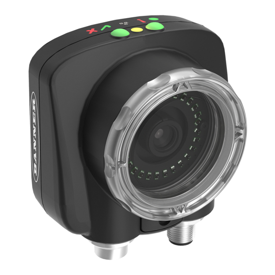
Features and Indicators
Note: Integrated display models: The touchscreen display has a plastic cover to protect the display. Remove this cover when
configuring the device. When the display is not in use, keep the display covered to protect it.
Installation Instructions
Mount the iVu
The iVu requires a bracket for mounting. Brackets are available from Banner Engineering. See
iVu to be mounted either perpendicular to the part or at an adjustable angle.
1. Position the iVu on the bracket.
2. Thread three M4 x 4 mm screws (supplied) through the bracket into the mounting holes in the bottom of the iVu.
Original Document
178442 Rev. F
Figure 1. Features
Figure 2. Mounting Bracket Mounting Holes
24 September 2019
www.bannerengineering.com
1. Power LED
Green: Ready/Power
Red (blinking or steady): Error
2. Pass/Fail LED
Green (steady): Pass
Green (blinking): Error
Red: Fail
3. Ethernet I/O LED
Green: Connected
Off: Disconnected
4. Focusing Window
5. Focusing Window Locking Clip
6. Integrated Display (integrated display models
only)
www.bannerengineering.com
. The brackets allow the
. Search for p/n
178442
Advertisement
Table of Contents

Related Manuals for Banner iVu Plus Color Gen2


Summary of Contents for Banner iVu Plus Color Gen2
- Page 1 Installation Instructions Mount the iVu www.bannerengineering.com The iVu requires a bracket for mounting. Brackets are available from Banner Engineering. See . The brackets allow the iVu to be mounted either perpendicular to the part or at an adjustable angle. 1. Position the iVu on the bracket.
-
Page 2: Cable Connections
iVu Plus TG and Color Gen2 Image Sensors 3. Tighten all three screws. 4. Mount the iVu and bracket to the machine or equipment at the desired location. Do not tighten the mounting screws at this time. 5. Check the iVu alignment. 6. -
Page 3: Demo Mode
iVu Plus TG and Color Gen2 Image Sensors 1. Confirm the network connections. Click the Start button, then on the Start menu, click Control Panel. b) In Control Panel, click Network and Internet, then click Network and Sharing Center, and then click Change adapter settings. Right-click on the connection that you want to change, then click Properties. -
Page 4: Device Main Menu
iVu Plus TG and Color Gen2 Image Sensors Figure 6. System Menu Figure 5. Select Type Screen Note: Switch between Live Mode and Demo Mode any time by going to Main Menu > System > Mode. Device Home Screen Use the Home screen on the iVu display to monitor inspections and to configure the iVu. Typically, the part being inspected is centered on the screen with the feature of interest bounded by the Region of Interest (ROI), a rectangle as shown below. - Page 5 iVu Plus TG and Color Gen2 Image Sensors Inspection Color Compare ROI and Mask Color Tolerance ROI and Mask Area Sensors Intensity Tolerance Intensity Range Area Range Color Area ROI and Mask Pass Count Color Select Color models only Area Range Pass Total Area Pass Count Blemish...
-
Page 6: Icon Reference
iVu Plus TG and Color Gen2 Image Sensors Auto Exposure Imager System Mode Live Exposure Demo Gain Trigger Save to USB Configuration Focus Load from USB External Strobe Reset to Defaults Information Internal Lock Device Connection Communications Ethernet I/O Resolution Grayscale models only Serial I/O Status... -
Page 7: Display Icons
• Capture the shape and form of the target object with lighting that optimizes its contrast and separates it from the background. Depending on the target, this may mean the integral ring light is not the best choice and other Banner lights should be considered. - Page 8 iVu Plus TG and Color Gen2 Image Sensors Figure 11. Exposure Screen 4. Go to Main Menu > Imager > Focus to adjust the focus while monitoring the Focus Number: Figure 12. Focus Screen 5. If you have an iVu color model, perform the white balance procedure to adjust the intensities of the color in the image so that the colors most closely match the actual objects.
- Page 9 iVu Plus TG and Color Gen2 Image Sensors Adjust the Focus on a C-Mount Lens Model 1. Remove the lens enclosure. 2. Adjust the focus while monitoring the focus number. To ensure the best image, adjust the focus until the focus number peaks. 3.
-
Page 10: Ivu Plus Communication Summary Of Ethernet And Serial
iVu Plus TG and Color Gen2 Image Sensors Figure 17. New Inspection Screen 4. Click Done. The newly created inspection will now be the currently running inspection. Trigger Main Menu > Imager > Trigger A trigger is a signal that tells the iVu to capture an image and inspect it. Five trigger options are available: •... -
Page 11: Communication Channels
iVu Plus TG and Color Gen2 Image Sensors Communication Channels The iVu supports up to four communications channels. To access the channels, go to Main Menu > System > Communications. Figure 20. Communications Menu • Command Channel—A bi-directional communication protocol that currently supports ASCII and enables other devices to remotely control the iVu and access device information and inspection results •... - Page 12 You agree to indemnify and hold Banner and its affiliates and channel partners harmless from any and all claims, liability and expenses, including reasonable attorney's fees and costs, arising out of your use of the Services or breach of this Agreement (collectively referred to as "Claims"). Banner reserves the right at its sole discretion and at its own expense, to assume the exclusive defense and control of any Claims.
Need help?
Do you have a question about the iVu Plus Color Gen2 and is the answer not in the manual?
Questions and answers