
Related Manuals for Banner SX5


Summary of Contents for Banner SX5
- Page 1 SX5 Safety Laser Scanner Instruction Manual Original Instructions 208913 Rev. A 29 November 2018 © Banner Engineering Corp. All rights reserved 208913...
-
Page 2: Table Of Contents
SX5 Safety Laser Scanner Contents 1 About This Document ..............................5 1.1 Important . . . Read This Before Proceeding! ..........................5 1.2 Use of Warnings and Cautions ................................ 5 1.3 EU Declaration of Conformity (DoC) ............................... 5 2 Product Overview ................................ - Page 3 SX5 Safety Laser Scanner 4.3.5 Preparing for System Operation ............................45 4.3.6 Machine Interface Connections ............................45 4.3.7 Wiring Diagrams ..................................46 5 Initial Checkout ................................49 5.1 Apply Initial Power and Configure the Scanner ..........................49 5.2 Verify the Optical Field (Initial Verification) ............................49...
- Page 4 11.3 Cleaning the Screens ..................................90 11.4 Replace Your Scanner ................................90 11.5 Repairs ......................................91 11.6 Contact Us ....................................91 11.7 Banner Engineering Corp Limited Warranty ..........................91 12 Standards and Regulations ............................92 12.1 Applicable U.S. Standards ................................92 12.2 Applicable OSHA Regulations ..............................92 12.3 International/European Standards...
-
Page 5: About This Document
The precautions and statements used throughout this document are indicated by alert symbols and must be followed for the safe use of the SX5 Safety Laser Scanner. Failure to follow all precautions and alerts may result in unsafe use or operation. -
Page 6: Product Overview
5.5 meters Maximum Warning Zone range 40 meters 2.1 Models A SX5 Safety Laser Scanner System refers to the laser scanner, cordsets (ordered separately), and mounting hardware (ordered separately). Interfacing solutions include safety modules, controllers, and muting modules. Model Description... -
Page 7: Features
• Observe all technical data and ambient conditions. For industrial use only — The SX5 can cause radio interference and is not suitable for use in residential areas. Only use the Scanner in industrial environments. Not for use on vehicles with combustion engines — The SX5 is not suitable for use on vehicles with combustion engines, because alternators or ignition systems can cause EMC disturbances. -
Page 8: Product Specification Label
Ensure that there are no other photoelectric sources within the SX5 detection plane that can impair performance. Monitoring through a window restriction — Do not use the SX5 to monitor an area (scan) through any window or transparent materials. Doing so can result in false detection that will cause nuisance machine stoppages. -
Page 9: Appropriate Applications
Qualified Persons in accordance with this manual and applicable safety regulations. The SX5 Safety Laser Scanner must be integrated into the machine's control system in such a way that an activation of the safety function safely stops or interrupts the dangerous process before a person can be endangered. -
Page 10: Control Reliability: Redundancy And Self-Checking
2.3.2 Control Reliability: Redundancy and Self-Checking Redundancy requires that the SX5 Safety Laser Scanner circuit components be backed up to the extent that, if the failure of a single component will prevent effective machine stopping action when needed, that component must have a redundant counterpart which will perform the same function. - Page 11 • In this example, the SX5 is mounted in the center of the operator work station to maximize the available size of the Safety and Warning Zones. The SX5 is mounted directly to the cell's perimeter guarding fencing 300 mm above the floor to prevent crawling under the Safety Zone.
- Page 12 (for example, perimeter guarding). The purpose of the safeguarding located at the perimeter of the work cell is primarily to detect entry into the hazardous area, while the area guarding (for example, the SX5) is responsible for preventing machine restart or other machine hazards while the individual remains within the work cell.
- Page 13 In addition to the typical considerations for horizontal stationary area guarding listed in example #1: • Install multiple SX5 with a vertical offset height of 100 mm (or more) or use physical shielding to prevent one SX5 from interfering with another SX5.
- Page 14 Safety Zone Length (Minimum Distance D): For this example, assume a maximum vehicle speed of 1200 mm/s (48 in/s), a breaking distance of 900 mm (35 in), SX5 response time of 122 ms (4 scans), the response time of a vehicle drive and safety interfacing 100 ms, which results in an overall stopping distance of 1166 mm (46 in).
- Page 15 Two SX5s are used to create four Safety Zones to cover each end of the pallet load/unload station (e.g. left side SZ, right side SZ, and both sides SZ). When no pallets are at the station, the front SX5 has a Safety Zone that covers both sides;...
-
Page 16: Operating Features
Safety Zone has a critical effect on the separation (safety) distance. If there is an angular movement of the SX5 that causes the Safety Zone to be positioned closer to the hazard, an individual could access the hazard before the machine can stop. -
Page 17: Passwords
2.6 Passwords Improperly set parameters on the SX5 can cause serious accidents. The configuration of the SX5 is therefore protected by passwords. SX5soft is not password protected. Users can create and save (to the PC) a configuration file without entering a password. -
Page 18: For Safe Laser Use (Class 1 Or Class 2)
The configuration settings are created by a trained and Qualified Person who understands the SX5 instruction materials. These settings are saved in an .xml configuration file and includes all the information that the SX5 requires for its intended operation. An SX5's configuration file includes the following data: •... -
Page 19: Safety And Warning Zones
Safety Zone and Warning Zone settings are created and saved as zone sets. Up to 6 configurable zone sets are available for the SX5. Zone sets can be enabled or disabled, one set at a time, while the SX5 is operational and actively monitoring a work area. -
Page 20: Specifications
SX5 Safety Laser Scanner • The device mounting and connections, must be carried out by qualified personnel only, according to the instructions included in the mechanical installation and electrical connection sections of this manual and applicable standards. • The safety laser scanner must be securely placed in a particular position so that access to the dangerous zone is not possible without passing through the Safety Zone of the scanner. -
Page 21: Dimensions
SX5 Safety Laser Scanner Safety Data Features Type 3 (EN 61496-1) Safety protective field range: 3 m, 5.5 m SIL 2 (IEC 61508) Warning field range: 40 m with remission of target = 90% (white) Category 3 (EN ISO 13849-1) Scanning angle: 275°... -
Page 22: Install Your Scanner
10. If required, install means to protect the SX5 from physical damage, sources of optical interference (e.g. other scanners), or prevent the SX5 from being used as a climbing aid. Ensure that these means do not impair the SX5's field of view. -
Page 23: Unmonitored Areas
Behind and To the Sides of the Scanner The area behind and on either side the SX5 is not monitored. It must not be possible to walk in unmonitored areas or otherwise access them. This can be accomplished by recessing the SX5 into the machine, using supplemental safeguarding, or using mechanical barriers to prevent access. - Page 24 Objects that are located within the Safety Zone create an unmonitored area directly behind the object. This area is best described as a shadow, since the light emitted by the SX5 cannot bend around or penetrate through solid objects. The shadow effect can be caused by both opaque and transparent objects.
-
Page 25: Adjacent Sx5S
Interference from adjacent SX5s may cause the OSSDs to go to the OFF state. • SX5s with a clear line of sight to another SX5 and that share the same detection plane with it, must be adjusted or shielded so that their light pulses are not detected by the adjacent SX5s. -
Page 26: Light Interference
The passive light sources can be an incandescent lamp, sunlight, a fluorescent light, a strobe light or other infrared light sources. Do not install the SX5 Safety Laser Scanner near strong and/or flashing light sources. Ambient light may interfere with the functioning safety laser scanner. If the installation requires direct exposure to ambient light, the scanner must be positioned so that the light does not enter the output window within ±5°... -
Page 27: Highly Reflective Backgrounds
3.2.4 Highly Reflective Backgrounds If there is a highly reflective background within 3 meters of the safety zone boundary, for example a metallic glossy surface, the SX5 Safety Laser Scanner might fail to recognize the exact distance of the detected object. Figure 21 Figure 22 In this situation, it is recommended to reduce or remove the reflecting background. -
Page 28: Dust Filtering
Use a HIGH dust filter level in dirty environments to filter (ignore) detection of airborne particles to ensure that they do not cause the scanner to detect objects in the zone set when nothing is present. This makes the SX5 Safety Laser Scanner less sensitive to dust and avoids shutting down the machinery unnecessarily. -
Page 29: Minimum Safety (Separation) Distance For Stationary Applications
Response Time Considerations — The SX5’s mirror rotates every 30 ms (33.3 scans [revolutions] per second). The safety outputs will switch off only after an object is detected in the Safety Zone for at least two consecutive scans. The SX5’s minimum response time is therefore 62 ms (2 ×... -
Page 30: Minimum Safety (Separation) Distance Formula
(OSSDs) being in the OFF state. This is channels, and the response time of all devices or controls that the response time of the SX5. react to stop the machine (e.g., UM-FA-9A safety module). See t2 is the maximum response time of the machine, i.e. -
Page 31: Reducing Or Eliminating Pass-Through Hazards
This method of safeguarding relies upon the location of the reset switch as well as safe work practices and procedures to prevent an unexpected start or restart of the guarded machine. The SX5 Safety Laser Scanner provides a configurable Manual Start/Restart (Latch Output) function for these applications. -
Page 32: Reset Switch Location
WARNING: Use of the Banner device for Access or Perimeter Guarding If a Banner device is installed in an application that results in a pass-through hazard (for example, perimeter guarding), either the Banner device or the Machine Primary Control Elements (MPCEs) of the guarded machine must cause a Latched response following an interruption of the defined area. -
Page 33: Mobile Applications
• IEC 61496-3 ―Requirements for Active Opto-Electronic Protective Devices Responsive to Diffuse Reflection (AOPDDR)‖ The user must also regularly check the safeguarding function of the SX5, and the speed and braking functions of the mobile Initial Checkout vehicle (see on page 49). -
Page 34: Safety Zone Area - Length And Width
SX5 Safety Laser Scanner 3.9.1 Safety Zone Area - Length and Width The horizontal Safety Zone will prevent a collision only if the edge of the field in the direction of movement is sufficiently distant from the vehicle and its load. This dimension (length) of the Safety Zone is described as the Minimum Distance D. -
Page 35: Additional Distance Factors (Z) Specific For Mobile Applications
SX5 Safety Laser Scanner Safety Zone (SZ) LEFT Scanner Mobile Mobile Vehicle Vehicle RIGHT LEAD Figure 28. Calculating the minimum distance in a mobile vehicle application = [V × (T )] + D where: = Stopping distance in mm = the maximum velocity as stated by the manufacturer of the mobile vehicle... -
Page 36: Mounting Your Scanner For Mobile Applications
Unmonitored Areas—Mounting the SX5 on the mobile vehicle must not create unmonitored areas between the Safety Zone and the vehicle, such that the SX5 cannot respond to an object with a cross-section of 70 mm or more. Unmonitored areas on a mobile vehicle can be prevented by: •... -
Page 37: Mounting The Scanner Directly To A Surface
SX5 Safety Laser Scanner • Mounting the Scanner recessed within the vehicle • Mounting the Scanner under a physical guard or overhanging parts of frame • Using supplemental safeguarding, such as bumper or edge switches • Using mechanical barriers to prevent access 3.10.1 Mounting the Scanner Directly to a Surface... -
Page 38: Mounting The Scanner And Adjusting The Angle
SX5 Safety Laser Scanner 1. Remove the M4 roll adjustment screws and washers (7), then align the M5 wall mounting screws (9). 2. Mount the roll adjustment bracket (8) to the wall or panel by inserting two M5 UNI 5933 screws (9). Tighten them, alternating between the two, until they are tight (torque to 2.5 to 3 N·m). -
Page 39: Adjusting The Roll Angle
Figure 35. Adjust the roll angle 3.10.6 Scanner Mounting Safety Information Verify the protection level assured by the SX5 Safety Laser Scanner is compatible with the danger level of the working machine, according to EN ISO 13849-1 or EN 62061. - Page 40 SX5 Safety Laser Scanner • Mounting and connecting the device must be carried out by qualified personnel only, according to the indications included in the specific sections and in the applicable standards. • Securely install the safety laser scanner so that access to the dangerous zone is not possible without passing throughout the safety area.
-
Page 41: Electrical Connections
SX5. It is good wiring practice (and may be required by code) to isolate the SX5 cables from high-voltage wires, avoid routing cables close to noisy wiring, and provide a good earth ground connection to the cordset shield. -
Page 42: Initial Electrical Connections
Ensure that electrical power is not applied to the SX5 until told to do so. Do not connect any wires to the machine control circuits (i.e. OSSD outputs) at this time. -
Page 43: Connecting The Fsd Interfacing
Depending on the application, the use of FSDs can facilitate controlling voltage and current that differs from the OSSD outputs of the SX5. FSDs can also be used to control an additional number of hazards by creating multiple protective stop circuits. -
Page 44: Machine Primary Control Elements And External Device Monitoring
46 (see also on page 32). When the SX5 is configured for Automatic Start/Restart (Reset), to properly monitor the MPCEs an External Device Monitoring (EDM) function must be provided by an external means from the Scanner. One example using the UM-... -
Page 45: Warning (Auxiliary) Output
After the initial trip test has been performed (see on page 50), and the OSSD safety output connections have been made to the machine to be controlled, the SX5 is ready for testing in combination with the guarded machine. The operation of the SX5 with the guarded machine must be verified before the combined SX5 and machine may be put Checkout into service. -
Page 46: Wiring Diagrams
SX5 Safety Laser Scanner Signal Function Connection Muting Lamp OSSD OSSD 1/1 OSSD 1/2 4.3.7 Wiring Diagrams Wiring with FSD Inputs Scanner +24V dc 0V dc 8-pin Male Euro-style 2 - Brown +24 V dc face view Functional Earth 8 - Red... - Page 47 SX5 Safety Laser Scanner Wiring Using a UM Module +24V dc 0V dc Scanner 8-pin Male Euro-style 2 - Brown +24 V dc Fuse face view 1.6 A Functional Earth 8 - Red 7 - Blue 0V dc UM-FA-9A 6 - Pink...
- Page 48 SX5 Safety Laser Scanner Wiring to a Safety Controller +24Vdc 0Vdc XS/SC26-2xx Scanner XS2so or XS4so 8-pin Male Euro-style +24Vdc 2 - Brown +24 V dc face view 0Vdc 8 - Red Functional Earth 7 - Blue 0V dc SO1a...
-
Page 49: Initial Checkout
For the initial checkout, the SX5 must be checked without power being available to the guarded machine. Final interface connections to the guarded machine cannot take place until the SX5 has been checked out. This may require lockout/tagout procedures (refer to OSHA1910.147, ANSI Z244-1, or the appropriate standard for controlling hazardous energy). -
Page 50: Perform A Trip Test
Warning Zones, use the display, when possible, to determine whether or not a zone has been interrupted. 1. Ensure that the SX5 is in Run mode, the Safety and Warning Zones are clear of intrusions, and the display shows one of the following: Zones are clear;... - Page 51 WARNING: If the Trip Test Indicates a Problem If the SX5 System does not respond properly to the trip test, do not attempt to use the System. If this occurs, the System cannot be relied on to stop dangerous machine motion when a person or object enters the sensing field.
- Page 52 SX5 Safety Laser Scanner • Ensuring a person is unable to remain between the Safety Zone and the dangerous parts of the machine undetected. • Ensuring access to the dangerous areas of the machine is not possible from any unprotected area.
-
Page 53: Configuration Instructions
Discovery and IP address setting features to facilitate remote configuration • Device Monitoring The software can be used with a SX5 connected or offline (without a SX5). A configuration can be saved and downloaded to a SX5 at a later time. 6.1.1 Response Time and Scan Cycle Setting The response time of the scanner is the time from when an object enters the Safety Zone to when the OSSD goes to the OFF state. -
Page 54: Muting Functions
OFF condition. The SX5 Safety Laser Scanner with Integral Muting monitors the mute devices to verify that their outputs turn on within the selected time of each other (order does not matter). If the inputs do not meet this simultaneity requirement, a mute condition will not occur. -
Page 55: Examples Of Muting Sensors And Switches
To disable a mute condition, connect the Mute Enable 1 pin to dc common (0 V dc) or leave it open The +24 V dc and 0 V dc should come from the same power supply as the SX5. Typical uses for Mute Enable include: 1. -
Page 56: Mute Lamp Output
Overriding a safeguarding device is the manual interruption or suspension of the normal function of a safeguard under supervisor control. Typically, an Override is needed to clear an object that is stuck within the SX5's Safety Zone, such as in an entry/exit application. -
Page 57: Muting Function T (X) (Bidirectional) Or L (Unidirectional) Selection
All the muting sensors are de-actuated and no beams of the Safety Zone are interrupted (in a unidirectional-muting configuration) The SX5's outputs stay on at the end of the override sequence (assuming the SX5's Safety Zone is clear, and it is configured for Automatic Restart). - Page 58 Figure 43. Muting function in the T configuration Use the L configuration when the SX5 is mounted vertically and Unidirectional is selected in the configuration. This configuration is suitable for applications requiring unidirectional movement of objects. This configuration uses two mute sensors (e.g.
-
Page 59: Install The Sx5Soft Software
SX5 Safety Laser Scanner 6.3 Install the SX5soft Software The SX5 Safety Laser Scanner is not required to install SX5soft on a PC. If the PC and SX5 are already connected, turn the power off to the SX5. Before installing SX5soft, close all Windows applications. -
Page 60: Main Menu
Change GUI Log Level—Verbose, Information or Error (Information is the default setting). Change GUI Log Options Help Laser Scanner Instruction Manual—Opens the SX5 Safety Laser Scanner Instruction Manual. Zip GUI log About—Opens a window that contains the SX5soft release version information. -
Page 61: Task Selection
New Safety System Configuration, the subpanel on the left side allows the selection of the device from the Catalogue list. Double-click a device to select it. To proceed with the configuration, click on the white >, in the upper right side on the main panel (under Banner name). www.bannerengineering.com - Tel: +1.763.544.3164... - Page 62 SX5 Safety Laser Scanner Figure 46. Configuration Settings screen The Application section of the Configuration Settings page allows users to define the application by selecting the scenario. • Expert Scenario selection provides the maximum configuration possibilities for the device; contains the entire set of parameters, regardless of the device use.
-
Page 63: Output Configuration
SX5 Safety Laser Scanner 6.5.1 Output Configuration Figure 47. Output Configuration screen Output Functions • OSSD—to select how many OSSD pairs are used for a given configuration. This component is connected to the machine control system and associated with the Safety Zone. If an object violates the Safety Zone, the OSSD pair switches to the OFF state effectively shutting down the machine. -
Page 64: Zone Set
SX5 Safety Laser Scanner 6.5.2 Zone Set A Zone Set is the combination of a configured Safety Zone (SZ) and Warning Zone (WZ). When active, a specific Zone Set has sole control of the safety outputs (OSSD1 and OSSD2) and the Warning auxiliary output, if set in the configuration. This function is useful to change the safeguarding area in applications in which a hazard is not continually present or in applications in which speed and stopping distances varies. - Page 65 SX5 Safety Laser Scanner WARNING: • Use Zone Set switching to change the area of safeguarding. • Failure to follow these instructions could result in serious injury or death. • Changing the Safety/Warning Zone Set from one pair to another must not expose any individual to a hazard or hazardous situation.
- Page 66 SX5 Safety Laser Scanner 3. Set the Zone parameters. This parameter group allows editing the Area Switch input combinations depending on how many Zone Sets are selected. The number of Area Switches (AS#) equal to the number of unassigned inputs will appear in the graphic.
-
Page 67: Input Configuration
SX5 Safety Laser Scanner 6.5.3 Input Configuration Figure 50. Input Configuration screen 1. Under Safety Zone in the Input Functions section, configure the Restart Mode. • Automatic—The scanner automatically returns the OSSD pair to the On-State after all detected objects are removed from the Safety Zone and the configured Recovery Time elapses. - Page 68 SX5 Safety Laser Scanner 5. Define the Timeout (minutes). This parameter allows the entering of a muting backdoor timer (maximum time to stay muted). The default time limit is 10 minutes. The time limit can be increased from 10 minutes to 1080 minutes in 1 minute increments. For no time limit, enter 0.
-
Page 69: Detection Configuration
SX5 Safety Laser Scanner 6.5.4 Detection Configuration Use the Detection Configuration screen to define the Safety Zone and Warning Zone parameters. Figure 51. Detection Configuration screen 1. Set the Number of Scans required to validate detection of a Safety Zone intrusion. -
Page 70: Create Or Edit Safety And Warning Zones
Include an additional distance in the Minimum Safety Distance calculations for these cases. See the graphs in the SX5's instruction Manual for these additional distances. Click on the white > arrow in the upper right corner to move to the next configuration screen. Click on the white < to return to the previous screen. -
Page 71: Use Teach In To Assign Safety And Warning Zones
SX5 Safety Laser Scanner 2. Select the zone shape from the options on the right side of the screen. When modifying an existing zone, you may copy zone shapes between zones (Safety and Warning), move a zone shape between zones (Safety and Warning), edit a zone shape, or delete a zone shape. -
Page 72: Validate And Accept The Configuration
6. Change the IP Address parameters in the Network Configuration screen to align them with the computer LAN. Important: The displayed IP address is assigned to the SX5. The successive address is also reserved because both internal micros have their own IP address. For example, if the displayed Scanner IP address is 192.168.0.10, the successive address of 192.168.0.11 is also assigned and... -
Page 73: Monitor The Scanner
SX5 Safety Laser Scanner 6.5.10 Monitor the Scanner When in the Monitoring mode, the graph displays the current working area of the scanner. Use this function to verify that the designed Safety and Warning Zones are designed correctly (provide the desired protection). This function is also used to watch the functioning of the scanner during operation. -
Page 74: Wink Function
SX5 Safety Laser Scanner 2. To edit an existing configuration on a Scanner on the network, follow these steps: a) In the software, click on Modify a Safety System Configuration from a Scanner on the Network. The software enters Discovery mode to search for all connected scanners. The software opens and displays the device with its IP Address (default is 192.168.0.10). -
Page 75: Change The Password
2. Go to the Scanner > Settings > Reset Password menu. 3. Contact Banner Engineering Technical Support and send the serial and the magic number shown. The "magic number" is based on the run-time of the scanner, so this number is time sensitive. To contact the Safety Application Engineering, call Banner's North American headquarters at 763-544-3164 or 1-888-373-6767 (toll free). -
Page 76: Operating Instructions
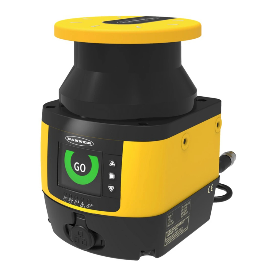
The SX5 has three buttons, a graphical display, and five status LEDs (located below the display). The SX5 has diagnostic LEDs for initial diagnostics. The OFF state and ON state LEDs are below the scanner's display. When it is not possible to see the display because of the way it was mounted or because it is hidden from the operator's position, use the software's Monitoring function to check the status. -
Page 77: Reset Signal Function
Internal Lockout conditions also require a manual reset to return to Run mode after the failure has been corrected. To reset/restart the SX5, close the reset/restart switch for 0.5 to 4.5 seconds and then open it. Closing the reset/restart switch too long causes the sensor to ignore the reset/restart request. -
Page 78: Checkout Procedures
• It is the user’s responsibility to verify proper operation on a regular basis. Study each procedure in its entirety, to understand each step thoroughly before beginning. Refer all questions to a Banner Contact Us applications engineer (see on page 91). -
Page 79: Perform A Commissioning Checkout
The Qualified Person must take precautions to ensure that no one is in or near the hazardous area during these safety system tests. 1. Examine the guarded machine to verify that it is of a type and design compatible with the SX5. For a list of Appropriate Applications appropriate and inappropriate applications, see on page 9. -
Page 80: Daily Checkout Procedure
Safety Zone boundary is identified (for example, marked on the floor), that it matches the corresponding Safety Zone. Do not continue until the SX5 System passes the trip test. Do not expose any individual to any hazard during the following checks. -
Page 81: Semi-Annual Checkout Procedure
Perform the Semi-Annual Checkout procedure every six months following system installation, or whenever changes are made to the SX5 configuration or to the machine. A copy of checkout results should be recorded and kept in the appropriate place (e.g., near or on the machine, in the machine’s technical file). -
Page 82: Troubleshooting
To recover from a Lockout condition: 1. Correct all errors. 2. Perform the reset routine or cycle power to the SX5 (power the SX5 down, wait five to 10 seconds, then power it up). 9.3 Display Icons... -
Page 83: Diagnostic Notes, Warnings, And Errors
SX5 Safety Laser Scanner Configuration Configuration Not Name Description Accepted Accepted The device is correctly functioning. The device has detected an object Safety Zone Signal in the Safety Zone. Reference points have moved. The display sector in the direction of Reference Point Signal the moved point is shown in blue. - Page 84 SX5 Safety Laser Scanner Icon Fault Code Device Status OSSD Status Description Muting has expired because it is maintained beyond the maximum Normal TIMEOUT timeout time. MUTING Muting has not activated because the correct sequence was not Normal followed. MUTING Normal The Muting function is active.
-
Page 85: Safety
SX5 Safety Laser Scanner Icon Fault Code Device Status OSSD Status Description INPUTCF2 Lockout Check the input sequence. Check the OSSD connections or the integrity of the external switching OSSDF1 Lockout device. If the failure persists, contact the factory for support. -
Page 86: Check For Sources Of Electrical And Optical Noise
All SX5 wiring is low voltage. Running these wires alongside power wires, motor/servo wires, or other high-voltage wiring can inject noise into the SX5. It is good wiring practice (and may be required by code) to isolate SX5 wires from high- voltage wires. -
Page 87: Accessories
SX5 Safety Laser Scanner 10 Accessories 10.1 Cordsets 8-Pin Threaded M12/Euro-Style to Flying Lead Cordsets for the SX5-B Model Length Style Dimensions Pinout (Female) SXA-815D 4.57 m (15 ft) SXA-825D 7.62 m (25 ft) 44 Typ. SXA-850D 15.2 m (50 ft) -
Page 88: Universal (Input) Safety Modules
Cleaning kit—1000 mls approved fluid for cleaning plastic, 100 soft lint-free cleaning cloths 10.4 Universal (Input) Safety Modules UM-FA-xA Safety Modules provide forced-guided, mechanically-linked relay (safety) outputs for the SX5 system when an 141249 external manual reset (latch) is desired by the application. See datasheet p/n for more information. -
Page 89: Contactors
SX5 Safety Laser Scanner 10.7 Contactors If used, two contactors per SX5 system that are monitored by the EDM circuit (performed by the reset line) are required. See 111881 Banner datasheet p/n for more information. Model Description 11-BG00-31-D-024 10 amp positive-guided contactor, 3 N.O., 1 N.C. -
Page 90: Product Support And Maintenance
Wet with cloth soaked in cleanser and wipe free in one swipe with cleaning cloth 11.4 Replace Your Scanner If it is necessary to replace your SX5, replace the SX5 with the same model and install it in the same position and alignment as the original SX5. -
Page 91: Repairs
Banner Engineering Corp. warrants its products to be free from defects in material and workmanship for one year following the date of shipment. Banner Engineering Corp. will repair or replace, free of charge, any product of its manufacture which, at the time it is returned to the factory, is found to have been defective during the warranty period. This warranty does not cover damage or liability for misuse, abuse, or the improper application or installation of the Banner product. -
Page 92: Standards And Regulations
12 Standards and Regulations The list of standards below is included as a convenience for users of this Banner device. Inclusion of the standards below does not imply that the device complies specifically with any standard, other than those specified in the Specifications section of this manual. -
Page 93: International/European Standards
SX5 Safety Laser Scanner 12.3 International/European Standards EN ISO 12100 Safety of Machinery – General Principles for EN 60204-1 Electrical Equipment of Machines Part 1: Design — Risk Assessment and Risk Reduction General Requirements ISO 13857 Safety Distances . . . Upper and Lower Limbs... -
Page 94: Glossary
SX5 Safety Laser Scanner 13 Glossary ANSI (American National Standards Institute) Auto Start/Restart (Trip) Condition Acronym for the American National Standards The safety outputs of a safety light screen system Institute, an association of industry representatives turn off when an object completely blocks a beam. In... - Page 95 Final Switching Device (FSD) permitted; failures which cause an unsafe condition The component of the machine’s safety-related (a failure to danger) are not. Banner safety products control system that interrupts the circuit to the are extensively FMEA tested. machine primary control element (MPCE) when the output signal switching device (OSSD) goes to the OFF-state.
- Page 96 SX5 Safety Laser Scanner Lockout Condition A safety light screen condition that is automatically attained in response to certain failure signals (an internal lockout). When a Lockout condition occurs, the safety light screen’s safety outputs turn Off; the failure must be corrected and a manual reset is required to return the system to Run mode.
- Page 97 (after the operation) by the operator. PSDI is commonly confused with "Trip Initiate." PSDI is defined in OSHA CFR1910.217. Banner safety light screen systems may not be used as PSDI devices on mechanical power presses, per OSHA regulation 29 CFR 1910.217.
- Page 98 When inserted into the defined area Banner safety light screen systems and safety and placed in front of a beam, the test piece causes modules are self-checking.
Need help?
Do you have a question about the SX5 and is the answer not in the manual?
Questions and answers