Table of Contents
Advertisement
Quick Links
LTF Time of Flight Laser Distance Sensor Quick Start Guide
Product Description
Laser distance sensor with both analog and discrete (switched) outputs
This guide is designed to help you set up and install the LTF Time of Flight Laser Distance Sensor. For complete information on programming,
performance, troubleshooting, dimensions, and accessories, please refer to the Instruction Manual at www.bannerengineering.com. Search for
p/n 194135 to view the manual. Use of this document assumes familiarity with pertinent industry standards and practices.
DO NOT USE THIS DEVICE FOR PERSONNEL PROTECTION
Using this device for personnel protection could result in serious injury or death.
•
This device does not include the self-checking redundant circuitry necessary to allow its use in personnel
safety applications. A device failure or malfunction can cause either an energized (on) or de-energized (off)
output condition.
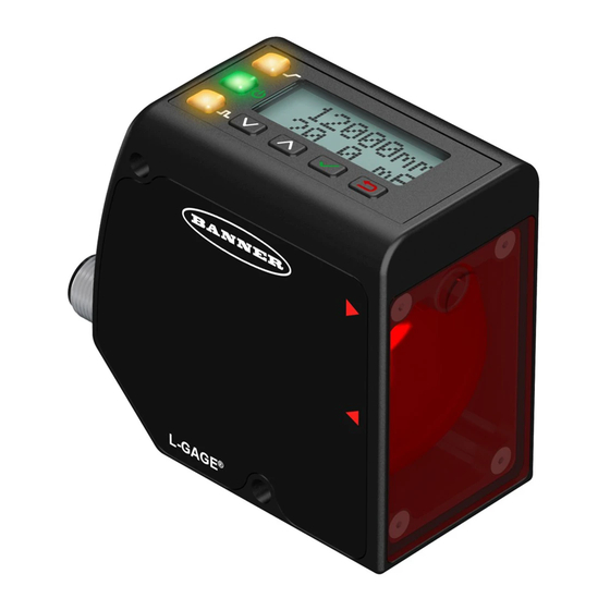
Features and Indicators
Analog Output
LED Indicator
Power
LED Indicator
Discrete Output
LED Indicator
Up and Down
Buttons
Enter Button
Escape Button
Figure 1: Features
Display
Figure 2: shown in Run Mode
Buttons and Icons
Use the sensor buttons Down, Up, Enter, and Escape to program the sensor and to access sensor information.
Down and Up Buttons
Press Down and Up to:
•
Access the Quick Menu from Run mode
•
Navigate the menu systems
•
Change programming settings
•
Change individual digit values in distance based settings
When navigating the menu systems, the menu items loop.
B
E
C
.
ANNER
NGINEERING
ORP
!
WARNING
Display
The display is a 2-line, 8-character LCD. The main screen is the Run mode screen, which
shows the real-time distance measurement and the analog output measurement.
January 24, 2023
Three LED indicators provide an ongoing indication of the sensing status.
Analog Output LED Indicator
Solid Amber = Displayed distance is within the taught analog out-
put window
Off = Displayed distance is outside the taught analog output win-
dow
Power LED Indicator
Solid Green = Normal operation, power On and laser On
Flashing Green (1 Hz) = Power On and laser Off (laser enable
mode)
Discrete Output LED Indicator
Solid Amber = Discrete Output is On
Off = Discrete Output is Off
Advertisement
Table of Contents

Related Manuals for Banner LTF Series


Summary of Contents for Banner LTF Series
- Page 1 LTF Time of Flight Laser Distance Sensor Quick Start Guide Product Description Laser distance sensor with both analog and discrete (switched) outputs This guide is designed to help you set up and install the LTF Time of Flight Laser Distance Sensor. For complete information on programming, performance, troubleshooting, dimensions, and accessories, please refer to the Instruction Manual at www.bannerengineering.com.
-
Page 2: Laser Description And Safety Information
• Mount open laser beam paths either above or below eye level, where practical. • Terminate the beam emitted by the laser product at the end of its useful path. Reference IEC 60825-1:2007, Section 8.2. © Banner Engineering Corp. www.bannerengineering.com... -
Page 3: Sensor Installation
194135) for more information on the options available from each menu. For TEACH options, follow the TEACH instructions in the instruction manual. In addition to programming the sensor, use the remote input to disable the buttons for security, preventing unauthorized or accidental program- ming changes. See the instruction manual for more information. © Banner Engineering Corp. www.bannerengineering.com... - Page 4 Access the Sensor Menu by pressing Enter from Run mode. The Sensor Menu is also accessible from the Quick Menu: navigate to MENU and press Enter. The Sensor Menu includes several submenus that provide access to view and change sensor settings and to view sensor informa- tion. © Banner Engineering Corp. www.bannerengineering.com...
- Page 5 S/N F..S..P..D.. INFO S/N Trigger Max Version 1.0.0 INFO Version Trigger Min Trigger Range Trigger TrackMax MENU RESET RESET No Trigger TrackMin RESET Yes (Continued on right side) Default Setting Figure 8: Sensor Menu Map © Banner Engineering Corp. www.bannerengineering.com...
- Page 6 For optimum performance, allow 15 minutes for the sensor to warm up Certifications Banner Engineering BV Turck Banner LTD Blenheim Park Lane, Culliganlaan 2F House, Blenheim Court, Industrial bus 3, 1831 Diegem, Wickford, Essex SS11 8YT, Control Equipment BELGIUM Great Britain 3TJJ Linearity/Accuracy © Banner Engineering Corp. www.bannerengineering.com...
-
Page 7: Repeatability Performance
2 (0.08) 2 (0.08) (6.6) (13.12) (19.7) (26.2) (32.8) (39.4) (6.6) (13.12) (19.7) (26.2) (32.8) (39.4) Distance in m (ft) Distance in m (ft) Figure 11: Speed: Standard (8 ms) Figure 12: Speed: Fast (1.5 ms) © Banner Engineering Corp. www.bannerengineering.com... -
Page 8: Banner Engineering Corp Limited Warranty
Banner Engineering Corp. warrants its products to be free from defects in material and workmanship for one year following the date of shipment. Banner Engineering Corp. will repair or replace, free of charge, any product of its manufacture which, at the time it is returned to the factory, is found to have been defective during the warranty period. - Page 9 IME OF LIGHT ASER ISTANCE ENSOR UICK TART UIDE Document title: LTF Time of Flight Laser Distance Quick Start Guide Part number: 194136 Revision: F Original Instructions © Banner Engineering Corp. All rights reserved. 194136 © Banner Engineering Corp. www.bannerengineering.com...
- Page 10 Mouser Electronics Authorized Distributor Click to View Pricing, Inventory, Delivery & Lifecycle Information: Banner Engineering LTF12IC2LD W/30 LTF12IC2LDQ LTF12IC2LD LTF12IC2LDQP LTF12UC2LD LTF12UC2LD W/30 LTF12UC2LDQ LTF12UC2LDQP LTF24IC2LD LTF24IC2LD W/30 LTF24IC2LDQ LTF24IC2LDQP LTF24UC2LD LTF24UC2LD W/30 LTF24UC2LDQ LTF24UC2LDQP...
Need help?
Do you have a question about the LTF Series and is the answer not in the manual?
Questions and answers