Advertisement
Quick Links
PVS28 Parts Verification Sensor Instruction
Manual
Features
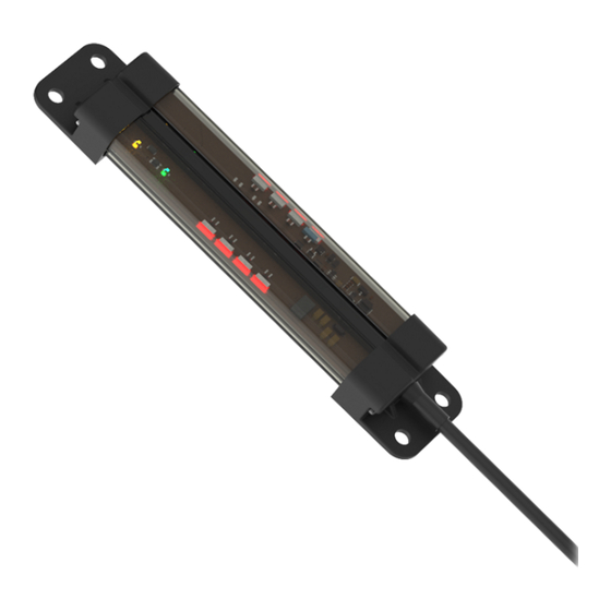
28 mm Programmable Multicolor Optical Sensor and Indicator
WARNING:
•
Do not use this device for personnel protection
•
Using this device for personnel protection could result in serious injury or death.
•
This device does not include the self-checking redundant circuitry necessary to allow its use in personnel safe-
ty applications. A device failure or malfunction can cause either an energized (on) or de-energized (off) output
condition.
Models
Family
PVS28
Overview
The PVS28 Parts Verification Sensor is an adjustable field optical sensor that can detect a wide variety of materials and objects.
Configure the sensor using software or remote input wires to sense objects up to a specific distance, ignoring objects beyond this distance
(background suppression), or within a windowed range.
Model
PVS28D
Original Instructions
July 20, 2023
•
Programmable using Banner's Pro Editor software and Pro Converter Cable
•
Up to 3 colors in one device (7 colors using Pro Editor)
•
Devices are completely self-contained—no controller needed
•
Teachable modes with color feedback for ease of use
•
Touchless activation removes the need for physical force to activate
•
Rated IP54
•
12 V DC to 30 V DC operation
•
Resistant to ambient light, EMI, and RFI interference
•
Sensing and indication in one device
Sensing Mode
D
Measurement
Detection Area
Reference Point
Detection not
possible
D0
D1
D0 (mm)
0
© Banner Engineering Corp.
Array Length
Connector
100
Reliable detection of a stationary
and moving object
Switch Point D1 (mm)
20
D2
Switch Point D2 (mm)
500
p/n: 233619 Rev. A
233619
Advertisement

Related Manuals for Banner PVS28 Series


Summary of Contents for Banner PVS28 Series
- Page 1 (background suppression), or within a windowed range. Measurement Detection Area Reference Point Detection not Reliable detection of a stationary and moving object possible Model D0 (mm) Switch Point D1 (mm) Switch Point D2 (mm) PVS28D 0 20 Original Instructions © Banner Engineering Corp. p/n: 233619 Rev. A July 20, 2023 233619...
- Page 2 PVS28 Parts Verification Sensor Instruction Manual Pro Editor Use Banner's Pro Editor software and Pro Converter Cable to create custom configurations by selecting different colors, flash patterns, and animations. For more information visit www.bannerengineering.com/proeditor. Wiring Diagrams – 12-30V dc 12-30V dc Pin 1 = Brown ...
- Page 3 PVS28 Parts Verification Sensor Instruction Manual NOTE: If a factory reset is performed through the Banner Pro Editor Software, the remote input wire becomes enabled (factory default setting). If the sensor is returned to factory defaults by using the remote input wire, the input wire re- mains enabled and the rest of the settings are restored to factory defaults. Remote Teach Use the following procedure to teach the Set Point. Pulse the remote input: ◦ 3x - Object Teach: The indicator alternates between a blue Teach Status color and the Signal Level color. ◦ 4x - Background Teach: The indicator alternates between a magenta Teach Status color and the Signal Level color. ◦ 5x - Window Teach: The indicator alternates between a cyan Teach Status color and the Signal Level color. ◦ 6x - Retroreflective Teach: The indicator performs a chase animation with a blue Teach Status color, with the Signal Level color as the background. Present the Set Point. Teach the Set Point. Action Result ...
- Page 4 Window Mode centers the total Detection Area at the Set Point plus and minus the Offset Value (50 mm default). Configuring a window near the minimum and maximum ranges shifts this window to ensure that it maintains this value. Use Window Mode when a change in state is de- sired within a specific narrow area, and not when outside this area. Five-pulse the remote input to enable Window Mode. Successfully entering Window Mode causes the device to alternate between the Teach Status color (Cyan) and the Signal Level color. page 4 July 20, 2023 © Banner Engineering Corp.
- Page 5 Detection Area Switch Point (D2) Reset the Sensor to Factory Defaults Reset the sensor to factory default settings using one of two methods. NOTE: If a factory reset is performed through the Banner Pro Editor Software, the remote input wire becomes disabled (factory default setting). If the sensor is returned to factory defaults by using the remote input wire, the input wire re- mains enabled and the rest of the settings are restored to factory defaults. Reset Using the Banner Pro Editor Software Go to Sensor › Factory Reset. The sensor indicators flash once, the sensor is reset back to the factory default settings, and a confirmation message displays. ...
-
Page 6: Specifications
–40 °C to +70 °C (–40 °F to +158 °F) Switching Frequency: 2 Hz Sensing Beam Discrete Output Response: 240 ms Infrared, 940 nm Sensor Array and Beam Spacing Environmental Rating 100 mm model: 2 sensors, 50 mm IP54 225 mm model: 4 sensors, 60 mm page 6 July 20, 2023 © Banner Engineering Corp. - Page 7 (2) il doit tolérer toute interférence, y compris celles susceptibles de provoquer un fonctionnement non souhaité du dispositif. Dimensions All measurements are listed in millimeters [inches], unless noted otherwise. July 20, 2023 page 7 © Banner Engineering Corp.
-
Page 8: Beam Pattern
PSW-24-1 • 24 V DC, 1 A power supply • 2 m (6.5 ft) PVC cable with M12 quick disconnect • Provides external power with splitter cable, sold separately ACC-PRO-CABLE5 • Mating accessory for cabled and terminal models • 150 mm (6 inch) PVC cable with M12 quick disconnect • Lever wire nuts included (qty 5) • Required to connect cabled models and screw terminal models to Pro Converter Cable, sold separately page 8 July 20, 2023 © Banner Engineering Corp. - Page 9 SMBPVA5C SMBPVA8 or SMBPVA10C NOTE: Standard mounting brackets are included with each PVS System. The following brackets are in addition to the standard brackets. SMBPVA2 • Set of 4 molded brackets • Snaps onto standard 28 mm (1.1 in) diameter pipe • 2 required per sensor July 20, 2023 page 9 © Banner Engineering Corp.
-
Page 10: Banner Engineering Corp Limited Warranty
Banner Engineering Corp. warrants its products to be free from defects in material and workmanship for one year following the date of ship- ment. Banner Engineering Corp. will repair or replace, free of charge, any product of its manufacture which, at the time it is returned to the factory, is found to have been defective during the warranty period. This warranty does not cover damage or liability for misuse, abuse, or the improper application or installation of the Banner product. ... - Page 11 All specifications published in this document are subject to change; Banner reserves the right to modify product specifications or update documentation at any time. Specifications and product information in English supersede that which is provided in any other lan- guage. For the most recent version of any documentation, refer to: www.bannerengineering.com. ...
Need help?
Do you have a question about the PVS28 Series and is the answer not in the manual?
Questions and answers