Advertisement
Quick Links
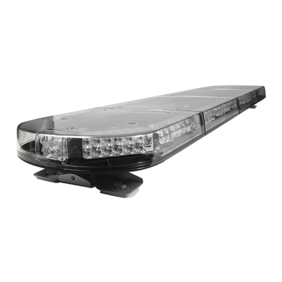
#EMG2000 MAGNUM™ LED DIRECT CONNECT Lightbar
IMPORTANT NOTICE TO INSTALLER: Make sure to read and understand all
instructions and warnings before proceeding with the installation of this product.
Ensure that the manual and any warning cards are delivered to the end user of
this equipment. Proper installation of the lightbar requires the installer to have a
thorough knowledge of automotive electronics, systems, and procedures. Lightbars
provide an essential function of an effective visual warning system. The use of
the lightbar does not insure that all drivers can or will abide by or react to an
emergency warning signal, especially at high rates of speeds or long distances. The
operator of the vehicle must never take the right of way for granted and it is the
operator's responsibility to proceed safely. The effectiveness of the lightbar is highly
dependant on the correct mounting and wiring. The installer must read and follow
the manufacturer's installation instructions and warnings in the manual. The vehicle
operator should verify daily that the lightbar is securely fastened to the vehicle and
properly functioning before operating vehicle. The lightbar is intended for use by
authorized personnel only. It is the user's responsibility to ensure they understand
and operate the emergency warning devices in compliance with the applicable city,
state and federal laws and regulations. SoundOff Signal assumes no liability for any
loss resulting from the use of this warning device.
Components/Contents
Standard Equipment:
1 - EMG2000 MAGNUM™ LED Lightbar built to your specifications
Other Parts that may be included depending on your configuration:
1 - Vehicle Specific Hook Kit w/ Hardware*
2 - Fixed Height Mounting Brackets w/ Hardware or
1 - Flat Mount Hardware Kit or
2 - Headache Brackets w/ Hardware
*Kits will vary with each lightbar depending on vehicle specified on
order form.
Unpack Lightbar
1. Remove the lightbar from box and packaging.
2. Save packaging for later shipping.
3. Check components/contents.
4. Please reference these instructions for proper wiring and
installation.
Tools Required for Installation
• 1/2" Socket with ratchet or 1/2" box end
• Phillips Head Screwdriver
• Drill bit #30
1.800.338.7337 / www.soundoffsignal.com
Installers and users must comply with all applicable federal, state and local laws regarding use and installation of warning devices. Improper use or installation may void
warranty coverage. To review our Limited Warranty Statement & Return Policy for this or any SoundOff Signal product, visit our website at www.soundoffsignal.com/sales-
support. If you have questions regarding this product, contact Technical Services, Monday - Friday, 8 a.m. to 5 p.m. or after hours 5 p.m. to 8 p.m. EST at 1.800.338.7337 (press
#4 to skip the automated message). Questions or comments that do not require immediate attention may be emailed to techservices@soundoffsignal.com.
S U P E R I O R C U S TO M E R R E L AT I O N S H I P S . S M A RT LY D E S I G N E D L I G H T I N G & E L E C T R O N I C S O L U T I O N S .
1
TABLE OF CONTENTS
PAGE
1
2
3
4-7
8
9
10
FLASH PATTERNS & WIRE FUNCTIONS
11
CONTROLLER & CONNECTOR INSTRUCTIONS
12
13
14
15
WARRANTY AND RETURN GOODS PROCEDURE
WARNING
•HIGH CURRENT interconnects must be properly terminated.
Poor crimp quality can cause heat build-up and fire. Follow crimp
connector manufacturer instructions.
•DO NOT install this product or route any wires in the Air
Bag Deployment Zone. Refer to vehicle Owner's Manual for
deployment zones.
•Do NOT use system to disconnect headlights, brake lights or
other safety equipment.
•Unit may become hot to touch during normal operation.
•Failure to properly install connectors, fuses or wiring may cause
vehicle failure or fire.
•Installation must only be performed by trained technician.
Installer must determine vehicle wiring configuration and proper
integration of system.
•Use proper wire gauge. All power wires connecting to positive
(+) or negative (-) battery terminal or local chassis ground (-)
must be sized to supply at least 125% of max. current and properly
fused at power source.
•Install protective grommets when routing wire through firewall
or metal.
This product contains high intensity LED devices. To
prevent eye damage, DO NOT stare into the light
NOTICE:
CONTENT
COMPONENTS/ CONTENTS
MODULE SPECIFICATIONS
WARNING
!
beam at close range.
EMG2000-DC 0419
Advertisement

Related Manuals for Soundoff Signal MAGNUM EMG2000


Summary of Contents for Soundoff Signal MAGNUM EMG2000
-
Page 1: Table Of Contents
Installers and users must comply with all applicable federal, state and local laws regarding use and installation of warning devices. Improper use or installation may void warranty coverage. To review our Limited Warranty Statement & Return Policy for this or any SoundOff Signal product, visit our website at www.soundoffsignal.com/sales- support. - Page 2 #EMG2000 MAGNUM™ LED DIRECT CONNECT Lightbar Fusion Boost 6 LED Inboard Module INPUT VOLTAGE RANGE: 10-16Vdc CURRENT DRAW: 0.5 Amps @ 12.8 Vdc (Flashing) 1.0 Amps @ 12.8 Vdc (Steady On) WATTAGE: 6.4W (Flashing) Fusion 12 LED Corner Module INPUT VOLTAGE RANGE: 10-16Vdc CURRENT DRAW: 0.8 Amps @ 12.8 Vdc (Flashing) 1.6 Amps @ 12.8 Vdc (Steady On) WATTAGE: 10.2W (Flashing)
-
Page 3: Technical/ Power Specifications
#EMG2000 MAGNUM™ LED DIRECT CONNECT Lightbar TECHNICAL SPECIFICATIONS TOP VIEW WITH COVERS ON Aluminum Base, Nylon base end caps, polycarbonate outer lenses, acrylic inner Material: lenses . Roof 1/4" bolt Stainless A2 Attachments: Operating -40º to +65º C Temperature: MODEL NUMBER # OF # OF &... -
Page 4: Fixed Height Brackets And Mounting
#EMG2000 MAGNUM™ LED DIRECT CONNECT Lightbar FIXED HEIGHT BRACKETS AND HOOK MOUNTING 1. Slide 5/16 carriage bolts into extrusion t-slots. Place mounting foot onto slots and tighten foot with washer and nut, ensuring the use of either a lock washer or lock nut 2. - Page 5 #EMG2000 MAGNUM™ LED DIRECT CONNECT Lightbar Extra Low & Permanent Mounting Foot FIXED HEIGHT BRACKETS PERMANENT MOUNTING 1. Locate the permanent hardware kit that is included. 2. Slide 5/16 carriage bolts into extrusion t-slots. Place mounting foot onto slots and tighten foot with washer and nut, ensuring the use of either a lock washer or lock nut.
- Page 6 #EMG2000 MAGNUM™ LED DIRECT CONNECT Lightbar Premium Fixed Height Foot Long T-Slot Bolts 2x 1.5° Wedge (use if necessary) FIXED HEIGHT BRACKETS AND HOOK MOUNTING (NON-PURSUIT) 1. Keeping the lightbar level with the road, attach Mounting Feet to the roof of the vehicle using the 2 Hook Bracket supplied T-Slot bolts.
- Page 7 #EMG2000 MAGNUM™ LED DIRECT CONNECT Lightbar Premium Fixed Height Foot Short T-Slot Bolts 2x Long T-Slot Bolts 2x 1.5° Wedge (use if necessary) FIXED HEIGHT BRACKETS AND HOOK MOUNTING (PURSUIT) 1. Attach the supplied screws to the mounting foot to secure the rubber pad as shown in Figure 3.
-
Page 8: Electrical Installation
#EMG2000 MAGNUM™ LED DIRECT CONNECT Lightbar ELECTRICAL INSTALLATION Featured Highlights: Standby Mode: If there is no +Vdc input to the 12 conductor wire harness for 180 seconds, the lightbar will go into a "Standy" mode. The standby mode is a low power mode that is used to extend the life of your battery. -
Page 9: Magnum Lightbar Speaker
UNIFORM TRAFFIC CODES. 3 LED HIGH OUTPUT CO SoundOff Signal assumes no liability for any loss resulting in the use of this warning device. During Installation: Do not route the speaker wires where they may interfere with the operations or deployment of the air bag or its sensors. - Page 10 #EMG2000 MAGNUM™ LED DIRECT CONNECT Lightbar DIRECT CONNECT FLASH PATTERNS AND WIRE FUNCTIONS 40Amp FUSE (Customer Supplied) DRAIN WIRE GROUND BLACK 12 GA. GROUND Pattern Name Sequence fpm* fps** Wire Color Standard Functions Quint Alternating 1.18 Pink Work Lights/Take Downs Warp Alternating 5.88...
- Page 11 #EMG2000 MAGNUM™ LED DIRECT CONNECT Lightbar LIGHTBAR CONTROLLER AND CONNECTOR INSTRUCTIONS Input Wire Input Group Control Light Output Groups Rear Inboard 3 Blue/White Front Inboard 2 Green Gray Front Inboard 3 Blue Rear Inboard 2 Green/White Front Inboard 1 Red, Yellow Blue Rear Inboard 1 Red/Yellow/White...
-
Page 12: Light Module Wire Harness Locations
#EMG2000 MAGNUM™ LED DIRECT CONNECT Lightbar LIGHT MODULE WIRE HARNESS LOCATIONS GREEN 23" BAR FRONT GREEN PASSENGER DRIVER SIDE SIDE GREEN GREEN 35.5" BAR REPLACEMENT OF INBOARD AND CORNER GREEN GREEN MODULES: 1. Disconnect main power. BLUE GREEN GREEN BLUE 2. -
Page 13: Magnum Troubleshooting
#EMG2000 MAGNUM™ LED DIRECT CONNECT Lightbar MAGNUM TROUBLESHOOTING NORMAL OPERATION Under normal operation the lightbar will Flash when a combination of the 12 input wires (except pattern select) are connected to +Vdc. The lightbar is OFF and in a low power Standby Mode 180 seconds after all inputs are removed from +Vdc. NO OPERATION No Power;... -
Page 14: Replacement Parts
#EMG2000 MAGNUM™ LED DIRECT CONNECT Lightbar 3 LED HIGH OUTPUT COLOR REPLACEMENT PARTS & ACCESSORIES ITEM # PART# DESCRIPTION ITEM # PART# DESCRIPTION PEMG2K00 EXTRA LOW MOUNTING FOOT KIT PEMG2DVDLC DIVIDER (LEXAN/CLEAR) PESF1K00 LOW PROFILE MOUNTING FOOT - EXT. PEMG2DVDXC DIVIDER (XYLEX/CLEAR) PREMIUM FIXED HEIGHT FOOT KIT - PEMG2AR103W... - Page 15 WARNING - DRILLING ANY HOLES INTO THE LIGHTBAR IS NOT SoundOff Signal will NOT accept returns without an RMA #. Each RMA # is good for only one (1) return and will expire (30) days after the date it was RECOMMENDED! THE RISK OF DAMAGING INTERNAL COMPONENTS issued.
Need help?
Do you have a question about the MAGNUM EMG2000 and is the answer not in the manual?
Questions and answers