Soundoff Signal Mpower EMPSC07M Series Installation Instructions Manual
Stop/tail & turn lights with clear duty technology
Hide thumbs
Also See for Mpower EMPSC07M Series:
- Manual (10 pages) ,
- Installation instructions manual (8 pages) ,
- Quick start manual (8 pages)
Advertisement
with Clear Duty® Technology
STOP/TAIL & TURN LIGHTS
EMPSC07M(x)-(x) - 7X3 Quick Mount, Screw Mount, & Stud Mount
EMPSB0C9(x)-(x) - 6X4 Quick Mount, Screw Mount, & Stud Mount
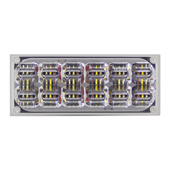
7X3 STOP/TAIL LIGHT
WARNING
•HIGH CURRENT interconnects must be properly terminated. Poor crimp quality can cause heat build-up and fire. Follow crimp connector
manufacturer instructions.
•DO NOT install this product or route any wires in the Air Bag Deployment Zone. Refer to vehicle Owner's Manual for deployment zones.
•Unit may become hot to touch during normal operation.
•Failure to properly install connectors, fuses or wiring may cause vehicle failure or fire.
•Installation must only be performed by trained technician. Installer must determine vehicle wiring configuration and proper integration of system.
•Use proper wire gauge. All power wires connecting to positive (+) or negative (-) battery terminal or local chassis ground (-) must be sized to
supply at least 125% of max. current and properly fused at power source.
•Install protective grommets when routing wire through firewall or metal.
1.800.338.7337 / www.soundoffsignal.com
1
®
Installers and users must comply with all applicable federal, state and local laws regarding use and installation of warning devices.
To review our Limited Warranty Statement & Return Policy for this or any SoundOff Signal product, visit our website at www.soundoffsignal.com/tech-services/returns/.
If you have questions regarding this product, contact Technical Services, Monday - Friday, 8 a.m. to 5 p.m. ET at 1.800.338.7337 (press #4).
Questions or comments that do not require immediate attention may be emailed to techservices@soundoffsignal.com.
6X4 STOP/TAIL LIGHT
NOTICE:
Improper use or installation may void warranty coverage.
E N H A N C I N G S A F E T Y T H R O U G H I N N O VAT I O N
MPOWER
®
STOP/TAIL
LIGHT
TECHNICAL SPECIFICATIONS
Input Voltage:
9-32Vdc
STOP/TAIL LIGHT
CURRENT CONSUMPTION (Amps)
12.8Vdc
25.6Vdc
Peak
STOP
0.42
TAIL
0.04
TURN SIGNAL LIGHT
CURRENT CONSUMPTION (Amps)
12.8Vdc
25.6Vdc
Peak
Average
Peak
TURN
0.66
0.33
0.33
AFTER POWER IS ON, touching the WHITE wire to the
ground will allow you to change various settings on the
module. (refer to page 6).
NOTE: It is recommended to use the Stud Mount
option for any dynamic mount surfaces (i.e.
Swining Panels, Doors, and Tail Gates).
WARNING
!
This product contains high intensity LED devices.
To prevent eye damage, DO NOT stare into the
light beam at close range.
Protected by U.S. Patent 10,703,260 and Patents Pending
https://soundoffsignal.com/legal/patent-notification/
Peak
0.21
0.02
Average
0.17
7x3 Silicone_STT 0321
Advertisement
Table of Contents

Related Manuals for Soundoff Signal Mpower EMPSC07M Series


Summary of Contents for Soundoff Signal Mpower EMPSC07M Series
- Page 1 Improper use or installation may void warranty coverage. To review our Limited Warranty Statement & Return Policy for this or any SoundOff Signal product, visit our website at www.soundoffsignal.com/tech-services/returns/. If you have questions regarding this product, contact Technical Services, Monday - Friday, 8 a.m. to 5 p.m. ET at 1.800.338.7337 (press #4).
- Page 2 ® QUICK MOUNT INSTALLATION 1. Drill a 3/4" wire hole. 2. Insert (4) silicone plugs into light to seal screw holes. with Clear Duty® Technology NOTE: Coating the exterior of the plug in 50% isopropyl alcohol, 50% water mix (Hand sanitizer works well) will allow the plug to slip into place FIG.
- Page 3 ® SCREW MOUNT INSTALLATION 1. Drill (4) 5/16 holes to mount light. Drill 3/4" wire hole. See Fig. 2 with Clear Duty® Technology 2. Insert well nuts into the 4 drilled holes. Fully seat to mounting surface. 3. Align the gasket to the mounting surface. NOTE: Horizontal and vertical orientations indicated on gasket for proper seal.
- Page 4 Improper use or installation may void warranty coverage. To review our Limited Warranty Statement & Return Policy for this or any SoundOff Signal product, visit our website at www.soundoffsignal.com/tech-services/returns/. If you have questions regarding this product, contact Technical Services, Monday - Friday, 8 a.m. to 5 p.m. ET at 1.800.338.7337 (press #4).
- Page 5 ® STUD MOUNT INSTALLATION 1. Drill (2) 1/4" holes to mount light. Drill 3/4" wire hole. See Fig. 2 with Clear Duty® Technology 2. Insert (4) silicone plugs into light to seal screw holes. NOTE: Coating the exterior of the plug in 50% isopropyl alcohol, 50% water mix (Hand sanitizer FIG.
- Page 6 WIRING AND TABLE INFORMATION ® OVER-VOLTAGE PROTECTION When an over-voltage condition is detected, the module will flash an over-voltage warning pattern of 50mS ON/950mS OFF to alert of the over- voltage condition and protect the electronics from damage due to heat/voltage. THERMAL COMPENSATION PROTECTION The LED module is designed to provide maximum power output while providing protection to the electronic components by reducing the output power at extreme temperatures.
- Page 7 SCHEMATICS ® TYPICAL TRAILER CIRCUIT AFTERMARKET RELAY ISOLATION 1.800.338.7337 / www.soundoffsignal.com...
- Page 8 Improper use or installation may void warranty coverage. To review our Limited Warranty Statement & Return Policy for this or any SoundOff Signal product, visit our website at www.soundoffsignal.com/tech-services/returns/. If you have questions regarding this product, contact Technical Services, Monday - Friday, 8 a.m. to 5 p.m. ET at 1.800.338.7337 (press #4).
Need help?
Do you have a question about the Mpower EMPSC07M Series and is the answer not in the manual?
Questions and answers