Advertisement
FASCIA LIGHTS - 4"
EMPS2QM(x)(x) - QUICK MOUNT
EMPS2SMS(x)(xxx)- SCREW MOUNT
EMPS2STS(x)(xxx) - STUD MOUNT THREADED
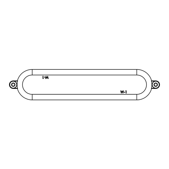
SCREW MOUNT
WARNING
•HIGH CURRENT interconnects must be properly terminated. Poor crimp quality can cause
heat build-up and fire. Follow crimp connector manufacturer instructions.
•DO NOT install this product or route any wires in the Air Bag Deployment Zone. Refer to
vehicle Owner's Manual for deployment zones.
•Unit may become hot to touch during normal operation.
•Failure to properly install connectors, fuses or wiring may cause vehicle failure or fire.
•Installation must only be performed by trained technician. Installer must determine
vehicle wiring configuration and proper integration of system.
•Use proper wire gauge. All power wires connecting to positive (+) or negative (-) battery
terminal or local chassis ground (-) must be sized to supply at least 125% of max. current
and properly fused at power source.
•Install protective grommets when routing wire through firewall or metal.
www.soundoffsignal.com/sales-support. If you have questions regarding this product, contact Technical Services, Monday - Friday, 8 a.m. to 5 p.m. at 1.800338.7337 (press #4 to skip the
1.800.338.7337 / www.soundoffsignal.com
1
TORX DRIVE SREWS x2
Installers and users must comply with all applicable federal, state and local laws regarding use and installation of warning devices.
Improper use or installation may void warranty coverage. To review our Limited Warranty Statement & Return Policy for this or any SoundOff Signal product, visit our website at
automated message). Questions or comments that do not require immediate attention may be emailed to techservices@soundoffsignal.com.
S U P E R I O R C U S TO M E R R E L AT I O N S H I P S . S M A RT LY D E S I G N E D L I G H T I N G & E L E C T R O N I C S O L U T I O N S .
TECHNICAL SPECIFICATIONS
Dimensions (From Mounting Surface)
Screw Mount:
4.52"L x 0.92"H x 0.42"D
Stud,Threaded Mount:
4.04"L x 0.92"H x 0.42"D
Adhesive Mount:
4.04"L x 0.92"H x 0.42"D
Input Voltage:
CURRENT CONSUMPTION
12.8Vdc
<1.0A
AFTER POWER IS ON, touching the WHITE wire to the ground will
allow you to change various settings on the module. (refer to pages 3 & 4)
NOTICE:
INSTALLATION:
Screw Mount
1. Pre-Drill per screw mount pattern indicated on page 10.
2. Deburr and clean the surface as required.
3. Make wire connections and feed the wire through the
drilled wire hole.
4. Install light with 2x Torx drive screws and hand tighten
only until mount surface and light are flush.
WIRE HOOK-UP TABLE
WIRE COLOR:
RED
BLACK
9-32Vdc
GREEN**
WHITE to GROUND
25.6Vdc
WHITE to POWER
<0.5A
RED/WHITE
** To sync multiple mPower lights, connect the Green
wire from each light together.
* Will NOT work w/ other sync products such as
Ghost, LED3, & Intersector.
*Will Work with Sync 2 products nFORCE Secondary Lights,
nFORCE FIT and Dual Color Intersector Lights
5
A FUSE
+Vd c
Sync
Set-up/Function
+Vd c
+Vd c
5
A FUSE
FUNCTION:
Power (Primary)
Ground
Sync2 *
Wire Function (See pg. 7)
Function Wire
Power (Secondary)
RED/WHITE
GREEN
WHITE
RED
BLACK
mPOWER 5.16
Advertisement
Table of Contents

Related Manuals for Soundoff Signal MPOWER EMPS2QM Series


Summary of Contents for Soundoff Signal MPOWER EMPS2QM Series
- Page 1 Installers and users must comply with all applicable federal, state and local laws regarding use and installation of warning devices. Improper use or installation may void warranty coverage. To review our Limited Warranty Statement & Return Policy for this or any SoundOff Signal product, visit our website at www.soundoffsignal.com/sales-support.
-
Page 2: Installation
INSTALLATION: Stud Mount, Threaded (Figure 1) 1. Pre-Drill per stud mount pattern indicated on page 10. 2. Clean the surface as required. 3. Make wire connections and feed wire through the drilled wire hole. 4. Install light, inserting 2 studs into the 2 drilled holes. 5. - Page 3 INSTALLATION: Edge-Mount Bracket 1. Install Heat Sink onto “mPOWER Stud Mount, Threaded” light as ndicated. Wire passed through center hole. 2. Install bracket onto “mPOWER Stud Mount, Thread” light as indicated. Wire passed through rear relief and into lower edge grip relief. 3.
- Page 4 INSTALLATION: Multi-Mount Bracket 1. Pre-drill mount holes as required (bracket holes and spacing are indicated on page 10). 2. Place bracket onto desired vehicle’s surface and secure with screws (not provided). 3. Install Heat Sink onto “mPOWER Stud Mount, Threaded” light as indicated.
- Page 5 INSTALLATION: Quick Mount w/Quick Clip 1. Feed wires through quick clip as shown. 2. Remove adhesive liner on the light and install clip to light. Make sure to properly align ends before placing down. 3. Route wires into recessed pocket lying flat in pocket. 4.
-
Page 6: Overvoltage Protection
OVER-VOLTAGE PROTECTION When an over-voltage condition is detected, the module will flash an over-voltage warning pattern of 50mS ON/950mS OFF to alert of the over-voltage condition and protect the electronics from damage due to heat/voltage. THERMAL COMPENSATION PROTECTION The LED module is designed to provide maximum power output while providing protection to the electronic components by reducing the output power at extreme temperatures. SYNC 2 Syncronizing the flashing of multiple light modules is accomplished by connecting the Green wires of different light modules together. - Page 7 FUNCTION TABLES Changing the function table is only enabled when the LED module is in a flashing mode (disabled in cruise or steady ON functions). The functional operation of the LED module can be changed while applying the +V to the Red wire with the black wire connected to ground.
- Page 8 COLOR SWAP This function is only valid for dual and tri-color light modules and can only be changed when the light module is in a flashing mode (disabled for single color modules and when light module is operating in cruise or steady ON functions). When the light is flashing, momentarily connect the white wire to ground for >2S and <3S (light will go steady high, steady low, off) then release.
- Page 9 REMOTE MODE: FOR USE WITH bluePRINT SYSTEM ONLY Connecting the Green wire to ground before applying power to the Red or Red/White wires will place the LED module into remote mode and the light output color will be directly controlled by the input wires as shown below. For Cruise mode or Low Power control of the LED module, the signal to the control wires must be 100 +/- 2Hz using the duty cycle inputs listed below to produce the light output.
-
Page 10: Important Note
SCREW MOUNT HOLE TEMPLATE QUICK MOUNT HOLE TEMPLATE 54.5mm 54.5mm [2.145”] [2.145”] WIRE THRU-HOLE DRILL Ø8mm [Ø.315”] PRE-DRILL WIRE THRU-HOLE 2x Ø1mm DRILL Ø 8mm [Ø.04”] [Ø.315”] STUD MOUNT THREADED HOLE TEMPLATE MULTI-MOUNT BRACKET 25mm 25mm 50mm [.98”±.01] [.98”±.01] [1.97”] 20mm [.787”] 2x DRILL INSERT...
Need help?
Do you have a question about the MPOWER EMPS2QM Series and is the answer not in the manual?
Questions and answers