Table of Contents
Advertisement
Quick Links
Advertisement
Table of Contents

Subscribe to Our Youtube Channel
Related Manuals for Njoy Ranger 30KT


Summary of Contents for Njoy Ranger 30KT
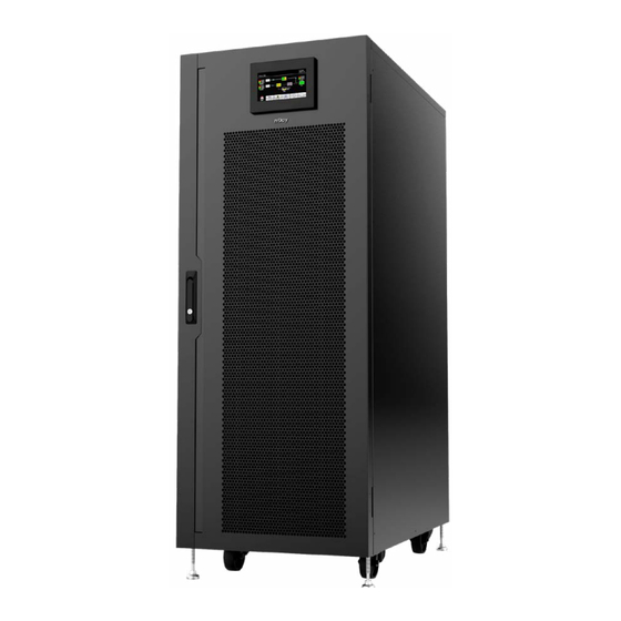
- Page 1 Ranger Series Ranger 30KT - UP33TOP130KRAAZ01B User Manual Ranger 60KT - UP33TOP160KRAAZ01B Ranger 120KT - UP33TOP112ZRAAZ01B Ranger 180KT - UP33TOP118ZRAAZ01B Before using this product, carefully read all product documentation and retain it for future reference. 232.21.23.0...
-
Page 2: Table Of Contents
Table of contents 1. Safety and EMC instructions .................. 5 1-1. Transportation and storage ..................5 1-2. Preparation ........................5 1-3. Installation ........................5 1-4. Connection warnings ....................6 1-5. Operation ........................7 1-6. Standards ........................7 2. Installation and operation ..................8 2-2. - Page 3 Thank you for purchasing our products! Please read this manual before using the product. This User Manual is compatible with the following Ranger Series models: 30K VA Ranger 30KT 60K VA Ranger 60KT 120K VA Ranger 120KT 180K VA Ranger 180KT...
- Page 4 WARNING Please comply with all warnings and operating instructions in this manual. This equipment should only be installed, serviced, and maintained by qualified personnel. If you are the beneficiary of this UPS and you encounter any problem with it, please contact authorized personel who installed the UPS.
-
Page 5: Safety And Emc Instructions
Safety and EMC instructions All safety instructions in this document must be read, understood and followed. 1.1. Transportation and storage • Please transport the UPS system only in the original packaging to protect against shock and damage. • The UPS must be stored in the room where the temperature is well regulated. -
Page 6: Connection Warnings
1.4. Connection warnings • There is no standard backfeed protection inside of the UPS. However, there are relays on the Input to cut off line voltage while the neutral is still connect to UPS. Input Rly Input Rly Main Main Input Input Input Rly... -
Page 7: Operation
Before working on this circuit 1. Isolate Uninterruptible Power Supply (UPS) 2. Then check for Hazardous Voltage between all terminals including the protected earth. Risk of Voltage Backfeed 1.5. Operation • Do not disconnect the grounding/earthing conductor cable on the UPS or the building wiring terminals under any circumstance. -
Page 8: Installation And Operation
2.1. Wiring terminal view 2.1.1 Ranger 30KT (UP33TOP130KRAAZ01B) RS-232 communication port USB communication port Emergency power off function connector (EPO connector) - Page 9 Diagram 1: Ranger 30KT rear panel...
- Page 10 2.1.2 Ranger 60KT (UP33TOP160KRAAZ01B) RS-232 communication port USB communication port Emergency power off function connector (EPO connector) Share current port Parallel port Intelligent slot External battery connector/terminal Line input circuit breaker/switch Maintenance bypass switch Input/Output terminal (Refer to diagram 2 and 3 for details) Line input terminal Output terminal Input grounding terminal...
- Page 11 Diagram 3: Ranger 60KT input/output terminal Diagram 2: Ranger 60KT rear panel...
- Page 12 2.1.3 Ranger 120KT (UP33TOP112ZRAAZ01B) RS-232 communication port USB communication port Emergency power off function connector (EPO connector) Share current port Parallel port Intelligent slot External battery connector/terminal Line input circuit breaker/switch Maintenance bypass switch Bypass input terminal (Refer to diagram 4 and 5 for details) Line input terminal (Refer to diagram 4 and 5 for details) Output terminal (Refer to diagram 4 and 5 for details) Cold start function button...
- Page 13 Diagram 4: Ranger 120KT Diagram 5: Ranger 120KT Front panel Terminal view...
- Page 14 2.1.4 Ranger 180KT (UP33TOP118ZRAAZ01B) RS-232 communication port USB communication port Emergency power off function connector (EPO connector) Share current port (only available for parallel model) Parallel port (only available for parallel model) Intelligent slot External battery connector/terminal Line input circuit breaker/switch Maintenance bypass switch (option) Bypass input terminal (Refer to diagram 6 and 7 for details) Line input terminal (Refer to diagram 6 and 7 for details)
- Page 15 Diagram 6: Ranger 180KT Diagram 7: Ranger 180KT Front panel Terminal view...
-
Page 16: Ups Positioning
2.2. UPS Positioning The UPS should be installed in the environment with free ventilation, less dust, optimum ambient temperature and humidity. The recommended ambient temperature is 20°C~25°C with 50% humidity. • Ambient temperature: 0°C~+40°C • Storage temperature: -15ºC ~ 60ºC •... -
Page 17: Operations
Operations 3.1. Initial operation Step 1. Before operation, make sure that the two strings of batteries are connected correctly in order of ”+,GND,-” terminals and the breaker of the battery pack is at “ON” position (only in case of external battery packs presence). -
Page 18: 3-2.1. Main Screen
NOTE! Setting/Advanced Menu is not detailed in this User Manual.. If you need assistance or have any warning or fault codes on your UPS screen, please contact the technician that installed the UPS. DO NOT attempt to modify any settings of the UPS unless you are a trained technician. -
Page 19: 3-2.2. Control Screen
3.2.2. Control screen Touch the icon to enter control sub-menu. Control screen Touch the icon to return back to main screen no matter it’s in any screen of any submenu. ON/OFF UPS It will show “Turn on UPS?” when UPS is off. It will show “Turn off UPS?”... - Page 20 Battery test It will show “Battery Test” if the UPS is not in test. Touch “Yes” to start battery test. Then, it will show “Battery testing..…” during battery test period. After few seconds, battery test result will show on the screen. Touch “Back” to return to main screen immediately or “No”...
- Page 21 ON/OFF Charger It will show “Turn on Charger?” when charger is off. It will show “Turn off Charger?” when charger is on. Touch “YES” to turn on or off the charger. Then, the screen will return to main screen. Touch “Back” to return to CONTROL screen immediately or “No” to cancel this operation and back to CONTROL screen.
-
Page 22: 3-2.3. Measure Screen
3.2.3. Measure screen Touch the icon to enter measure page. Touch the icon browse information. Touch the icon to return to main screen. Touch the icon to go back to previous menu. Measure screen page 1 LINE VOL: The real time value of R, S and T phase voltage, RS, ST, TR voltage and input frequency. -
Page 23: 3-2.4. Setting Screen
OUTPUT W: R, S and T output power in watt. OUTPUT VA: R, S and T output power in VA. OUTPUT W (%): R, S and T output power watt in percentage. OUTPUT VA (%): R, S and T output power VA in percentage. Total watt and VA: W(%)/Total VA(%): Total input load watt and VA in percentage. - Page 24 WARNING DO NOT attempt to modify any settings of the UPS unless you are a trained technician. If you need to change any settings of this UPS or you have technical warnings or faults shown on UPS screen, please contact the technician that installed the UPS.
- Page 25 Language: Set the LCD language. Input Source: Select the input source. There are two options: Line (utility) and generator. Line is default setting. This setting value will show on the main page. When “generator” is selected, the acceptable input frequency will be fixed at the range of 40~70Hz.
- Page 26 Advance Advance Password page It’s required to enter a password to access “ADVANCE” page. WARNING! This menu is intended for qualified personnel for installation and maintenance. If you need to change the settings of this UPS or have warnings or errors displayed on the UPS screen, please contact the technician who installed the UPS.
-
Page 27: 3-2.5. Information Screen
3.2.5. Information screen Touch the icon to enter information page. Touch the icon browse information. Touch the icon to return to main screen. Touch the icon to go back to previous menu. • BASIC information Basic Information Page1 MCU Version: MCU version. DSP Version: DSP version. - Page 28 PAR State: The information of parallel state. PAR ID: The UPS ID number in parallel state. Customer code: Customer code for UPS DynamicPasword: if Enabled, maintainer password is dynamic • RATED information Rated Information Page Output Voltage: It shows output rated voltage. Output FRE: It shows output rated frequency.
- Page 29 • PARAMETER information Parameter Information Page1 Line Voltage Range: The acceptable line input voltage range. Line FRE Range: The acceptable line input frequency range. Bypass Voltage Range: The acceptable input voltage range for bypass mode. Bypass FRE Range: The acceptable input frequency range for bypass mode. ECO Voltage Range: The acceptable input voltage range for ECO mode.
-
Page 30: 3-2.6. Data Log Screen
Shutdown Voltage: If battery voltage is lower this point, UPS will automatically shut down. Battery Age: It shows battery age. Battery AH: It shows battery AH Battery Number: It shows battery number. 3.2.6. Data Log screen Touch the icon to enter data log page. Data log is used to record the warning and fault information of the UPS. -
Page 31: Single Ups Operation
3.4. Single UPS operation WARNING This UPS should be started by authorized personal only. Please contact technician that installed the UPS if you need to perform additional tasks on UPS. 3.4.1. Turn on the UPS with utility power (in AC mode) •... - Page 32 • If the UPS is overload, the buzzer will beep twice every second. • If the UPS is overloaded, please remove some loads immediately. It is recommended to have the total loads connected to the UPS less than 80% of its nominal power capacity to prevent overload for system safety.
- Page 33 3.4.6. Test the batteries • If you need to check the battery status when the UPS is running in AC mode/CVCF mode, you could touch “CONTROL” and select “Battery Test”. Refer to “Battery Test” screen. • Users also can set battery self-test through monitoring software. 3.4.7.
-
Page 34: Fault Code
• Some warning alarms can’t be muted unless the error is fixed. Please refer to section 3-3 for details. 3.4.11. Operation in Fault mode • When Fault LED illuminates and the buzzer beeps continuously, it means that there is a fatal error with the UPS. Users can get the fault code from “DATA LOG”... - Page 35 Inverter C-A output (line Bypass O/P short to line) short circuited circuited Bypass O/P line to line Inverter A negative short power fault circuited Inverter B negative Inverter SCR short power fault circuited Inverter C negative BUS voltage drops too power fault fast Battery SCR short...
-
Page 36: Warning Code
3.6. Warning Code Warning Warning Warning event Warning event code code Line situations are different in Battery unconnected parallel system Bypass situations are IP Neutral loss different in parallel system Locked in bypass after IP phase abnormal overload 3 times in 30 minutes Bypass phase abnormal Converter current unbalanced Cover of maintain switch is... -
Page 37: Troubleshooting
Troubleshooting If the UPS system does not operate correctly, please solve the problem by using the table below. Problem Possible cause Solutions No indication and alarm in the front The AC input power is Check if input cable firmly display panel even not connected well. - Page 38 Problem Possible cause Solutions The UPS shut Fault code is down automatically Check output wiring and if shown as 14, because short circuit connected devices are in short 15, 16, 17, 18 occurs on the UPS circuit status. or 19. output.
-
Page 39: Storage And Maintenance
Storage and maintenance 5.1. Storage Before storing, charge the UPS at least 7 hours. Store the UPS covered and upright in a cool, dry location. During storage, recharge the battery in accordance with the following table: Storage Temperature Recharge Frequency Charging Duration -25°C - 40°C Every 3 months... - Page 40 • Batteries may cause electric shock and have a high short-circuit current. Please remove all wristwatches, rings and other metal personal objects before maintenance or repair, and only use tools with insulated grips and handles for maintaining or repairing. • When replacing the batteries, install the same number and same type of batteries.
- Page 41 Memo...
- Page 42 Memo...
- Page 43 Memo...
Need help?
Do you have a question about the Ranger 30KT and is the answer not in the manual?
Questions and answers